1
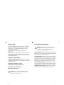
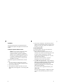
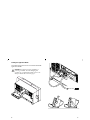
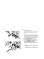
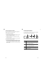
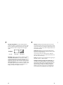
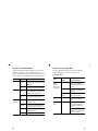
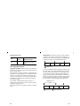
User Manual
TDS3SDI
601 Digital Video
Application Module
071-0787-00
*P071078700*
071078700
Copyright E Tektronix, Inc. All rights reserved.
Tektronix products are covered by U.S. and foreign patents,
issued and pending. Information in this publication supercedes
that in all previously published material. Specifications and
price change privileges reserved.
Tektronix, Inc., P.O. Box 500
Beaverton, OR 97077
TEKTRONIX and TEK are registered trademarks of
Tektronix, Inc.
WARRANTY SUMMARY
Tektronix warrants that the products that it manufactures and
sells will be free from defects in materials and workmanship
for a period of three (3) years from the date of shipment from
an authorized Tektronix distributor. If a product or CRT proves
defective within the respective period, Tektronix will provide
repair or replacement as described in the complete warranty
statement.
To arrange for service or obtain a copy of the complete
warranty statement, please contact your nearest Tektronix sales
and service office.
EXCEPT AS PROVIDED IN THIS SUMMARY OR THE
APPLICABLE WARRANTY STATEMENT, TEKTRONIX
MAKES NO WARRANTY OF ANY KIND, EXPRESS OR
IMPLIED, INCLUDING WITHOUT LIMITATION THE
IMPLIED WARRANTIES OF MERCHANTABILITY AND
FITNESS FOR A PARTICULAR PURPOSE. IN NO EVENT
SHALL TEKTRONIX BE LIABLE FOR INDIRECT,
SPECIAL OR CONSEQUENTIAL DAMAGES.
www.tektronix.com
Contacting Tektronix
Product
Support
For questions about using Tektronix measurement
products, call toll free in North America:
1-800-833-9200
6:00 a.m. – 5:00 p.m. Pacific time
Or contact us by e-mail:
[email protected]
For product support outside of North America,
contact your local Tektronix distributor or sales
office.
Service
Support
Tektronix offers a range of services, including
Extended Warranty Repair and Calibration
services. Contact your local Tektronix distributor or
sales office for details.
Contents
Installation . . . . . . . . . . . . . . . . . . . . . . . . . . . . . . . .
The 601 Digital Video Module . . . . . . . . . . . . . . . . . .
601 Digital Video Conventions . . . . . . . . . . . . . . . . . .
Accessing 601 Digital Video Functions . . . . . . . . . . .
Menu Changes . . . . . . . . . . . . . . . . . . . . . . . . . . . . .
Alternating Trigger Source . . . . . . . . . . . . . . . . . . . .
Specifications . . . . . . . . . . . . . . . . . . . . . . . . . . . . . .
4
13
14
15
19
36
37
Manual Storage
The oscilloscope front cover has a convenient place to
store this manual.
For a listing of worldwide service centers, visit our
web site.
Toll-free
Number
In North America:
1-800-833-9200
An operator can direct your call.
Postal
Address
Tektronix, Inc.
Department or name (if known)
P.O. Box 500
Beaverton, OR 97077
USA
Web Site
www.tektronix.com
1
Safety Summary
Review the following safety precautions to avoid injury
and prevent damage to this product or any products
connected to it. To avoid potential hazards, use this
product only as specified.
Only qualified personnel should perform service
procedures.
While using this product, you may need to access other
parts of the system. Read the General Safety Summary in
other system manuals for warnings and cautions related
to operating the system.
To Avoid Fire or Personal Injury
Do Not Operate With Suspected Failures. If you suspect there
is damage to this product, have it inspected by qualified
service personnel.
Do Not Operate in Wet/Damp Conditions.
Do Not Operate in an Explosive Atmosphere.
Keep Product Surfaces Clean and Dry.
Preventing Electrostatic Damage
CAUTION. Electrostatic discharge (ESD) can
damage components in the oscilloscope and its
accessories. To prevent ESD, observe these
precautions when directed to do so.
Use a Ground Strap. Wear a grounded antistatic wrist strap to
discharge the static voltage from your body while installing or removing sensitive components.
Use a Safe Work Area. Do not use any devices capable of
generating or holding a static charge in the work area where
you install or remove sensitive components. Avoid handling sensitive components in areas that have a floor or
benchtop surface capable of generating a static charge.
Handle Components Carefully. Do not slide sensitive compo-
nents over any surface. Do not touch exposed connector
pins. Handle sensitive components as little as possible.
Transport and Store Carefully. Transport and store sensitive
components in a static-protected bag or container.
Safety terms in this manual
CAUTION. These statements identify conditions
or practices that could result in damage to the
equipment or other property.
2
3
Installation
This section describes how to install and check the
TDS3SDI 601 Digital Video application firmware and
module.
Installing the Application Module Firmware
NOTE. You must install the application module
firmware the first time you install a new
application module. If you do not install the
firmware, the new application module may not
function at all, or may not function correctly. It
is strongly recommended that you install new
firmware when the oscilloscope indicates that
an update is necessary.
To install the application module firmware, do these
steps:
1. Save any oscilloscope settings and/or reference
waveforms to floppy disk before doing these steps.
2. Power off the oscilloscope.
3. If the application module came with one or more
floppy disks, insert floppy disk 1 into the floppy disk
drive.
4. Power on the oscilloscope. The oscilloscope checks
whether or not the firmware update is necessary. If an
update is necessary, go to page 5. If an update is not
necessary, go to page 7.
Firmware Update Required.
If a firmware update is necessary, the oscilloscope
displays the following message:
This procedure will replace the firmware in the
instrument with firmware from the floppy disk. This
procedure will take approximately 5 minutes.
Caution: Do not turn the instrument off or eject the
floppy disk until prompted.
Push ‘OK Load New Firmware’ to proceed.
Push MENU OFF to abort this procedure.
1. Push OK Load New Firmware to begin loading the
firmware. The oscilloscope shows a clock icon on the
screen while the firmware upgrade is in process. If a
second firmware floppy disk is required, the
oscilloscope will instruct you to eject the first disk
and insert the second disk.
If you do not want to upgrade the firmware, push
MENU OFF.
When the firmware upgrade is complete, the oscilloscope will restart automatically with the new firmware.
4
5
NOTE. If you power off the oscilloscope, eject the
floppy disk before prompted, or if there is a
power outage during the firmware upgrade
process, you must restart the firmware upgrade
procedure starting at step 2 on page 4.
2. The oscilloscope may also display the following
message:
WARNING! This instrument is not calibrated.
You must run Signal Path Compensation (SPC) in
order to calibrate the instrument.
SPC is adversely affected by input signals with
AC components. Disconnect or otherwise remove
these signals prior to running SPC. SPC will take
approximately 10 minutes to run.
Push ‘OK Compensate Signal Paths’ to begin the
calibration procedure. Or, you may run SPC in the
UTILITY Cal menu.
4. Proceed to step 1 of Firmware Update Not Necessary
on page 7 to finish the firmware installation.
Firmware Update Not Required.
If a firmware update is not necessary, the oscilloscope
displays the following message:
A floppy disk containing instrument firmware has
been detected. However, the firmware on the disk is
not newer than the instrument firmware. Therefore,
no firmware upgrade is required.
Push MENU OFF to remove this message.
1. Push the MENU OFF button.
2. Eject the floppy disk.
3. You are done installing the firmware. Go to Installing
the Application Module on page 8.
3. If the instrument has been operating for 20 minutes or
longer in the ambient temperature at which it will be
used, Push OK Compensate Signal Paths to run
SPC. You can also skip this step for now and run SPC
at a later time.
6
7
Installing the Application Module
The following figures show how to install the TDS3SDI
application module.
CAUTION. Turn off power before installing or
removing a module. To avoid damaging the
oscilloscope or application module, observe the
ESD precautions described on page 3.
ITU-R 601
8
9
Checking Module Installation
Do these steps to check that the TDS3SDI 601 Digital
Video application firmware and module are correctly
installed.
1. Power on the oscilloscope. Look at the oscilloscope
startup screen; it should list the 601 module. If the
oscilloscope displays a message stating that there is
incompatible firmware, power off the oscilloscope
and do the steps in the Installing the Application
Module Firmware, starting at step 2 on page 4.
2. Push the QUICKMENU panel button.
3. Push the Menu bottom button to select Video.
4. Push the SUBMENU bottom button to check that it
displays SDTV/HDTV and ITU-R 601.
If the oscilloscope does not show these menu items, do
the steps in Troubleshooting Module Installation on
page 12.
NOTE. You do not need to reinstall the firmware
if you remove and reinstall an application
module. However, the features provided by that
application module are not available until you
reinstall the module.
CH 2
CH 3
CH 4
10
11
Troubleshooting Module Installation
If the oscilloscope does not recognize the application
module at power-on, do these steps:
1. Power off the oscilloscope.
2. Follow the ESD precautions listed on page 3 as you
remove the application module.
3. Examine the oscilloscope and application module
contacts for damage.
4. Reinstall the application module into the oscilloscope.
5. Reinstall the firmware (page 4).
6. Power on the oscilloscope. If the oscilloscope still
does not display the application menu items as listed
in Checking Module Installation on page 11, power
off the oscilloscope and contact the nearest Tektronix
service center.
12
The 601 Digital Video Module
The following figure and table describe the 601 Digital
Video module connectors and indicators.
1
2
3
4
Item
Description
1
15-pin connector for analog component signal output.
Connect the output to oscilloscope channels 2 through 4
using the supplied cable assembly.
2
BNC connector for composite video output signal.
Connects to channel 1 of the oscilloscope. You can also
connect this signal to a video monitor.
3
BNC connector for ITU-R 601 video signal input.
4
Green LED that lights when the module recognizes a
valid 601 video signal.
13
601 Digital Video Conventions
Accessing 601 Digital Video Functions
The following conventions apply to the 601 Digital
Video module:
H This firmware update adds alternating trigger source
capability to the oscilloscope. Refer to page 36 for an
explanation of the alternating trigger source function.
The 601 Digital Video application module changes
several menus. The following sections describe how to
access the changed menus.
H You can use other menus while using the video
QuickMenu. For example, you can push the
MEASURE button to set up and take waveform
measurements, and then push the QUICKMENU
button to return to the video QuickMenu.
H You can trigger on and view SDTV and HDTV
analog signals. The 601 Digital Video module does
not convert HDTV digital formats (SMPTE 292M) to
analog.
H You cannot use video triggering to arm B triggering.
Video QuickMenu
The video QuickMenu contains bottom and side menu
items that are useful for quickly displaying and measuring analog SDTV/HDTV and 601-encoded video
signals. Vectorscope and Video Picture are accessible
from the video QuickMenu.
To display the video QuickMenu, do these steps:
1. Push the QUICKMENU panel button.
2. Push the Menu bottom button to select Video.
3. Push the SUBMENU button to select a video signal
standard (SDTV/HDTV or ITU-R 601) and display
bottom and side menus for that video type.
H The oscilloscope does not have video signal
clamping. Tektronix offers an optional Video Display
Clamp module (013-0278-00) that provides video
signal clamping.
H The TDS3SDI module is optimized for the TDS3054
DPO oscilloscope. The module provides reduced
performance in other TDS3000 Series oscilloscopes.
14
15
Video Trigger Settings in the Trigger Menu
Video Autoset Settings in the Acquire Menu
To access the new video trigger functions, do these steps:
1. Push the Trigger MENU panel button.
2. Push the Type bottom button to select Video. The
new video trigger functions are part of the Standard
trigger menus.
Video Autoset automatically sets up the oscilloscope to
trigger and display a composite video waveform. Video
Autoset is available in the ACQUIRE or QuickMenu
menus.
To access the video autoset function from the Acquire
menu, do these steps:
1. Push the Acquire MENU front panel button to
display the Acquire menu.
2. Push the Autoset bottom button to display the
Autoset side menu.
3. Push the Video Autoset side button to automatically
display a composite video waveform triggered on all
lines.
NOTE. 601 digital video functions are not
available in the Trigger menu.
ITU-R 601 Settings in the UTILITY > Apps Menu
To access the 601 Digital Video functions, do these
steps:
1. Push the UTILITY panel button.
2. Push the System bottom button to select Apps.
3. Push the Module button to select ITU-R 601. The
bottom and side menus change to show the 601
functions.
NOTE. The AUTOSET front-panel button always
runs the standard oscilloscope edge-trigger
autoset function.
NOTE. The Autoset menu shows which
component signal is connected to which
oscilloscope input. This information is not
shown in the video QuickMenu.
16
17
Vectorscope and Video Picture in the DISPLAY Menu
To access Vectorscope or Video Picture functions from
the Display menu, do the following:
1. Push the DISPLAY panel button.
2. Push the Vectorscope bottom button to display the
Vectorscope side menu.
3. Push the Video Picture bottom button to display the
Video Picture side menu.
NOTE. The DISPLAY Video Picture menu lets
you change the picture contrast and brightness
settings. These settings are not available in the
video QuickMenu.
Video Graticules (IRE/mV) in the DISPLAY Menu
To change the screen graticule to IRE or mV format, do
the following:
1. Push the DISPLAY panel button.
2. Push the Graticule bottom button to display the
graticule side menu. Push the -More- button to
display the IRE and mV buttons if they are not
already displayed.
3. Select IRE or mV on the side menu.
18
Menu Changes
The 601 Digital Video application module changes
several menus. The following sections list the menu
changes and describe the menu functions.
Video QuickMenu
The video QuickMenu displays bottom and side menus
that contain commonly-used functions useful for displaying and measuring standard broadcast, ITU-R 601,
and HDTV video signals.
There are two video types in the SUBMENU button:
ITU-R 601 and SDTV/HDTV. The following descriptions apply to both video types unless marked otherwise.
Video QuickMenu: bottom menu
Menu
item
Value
Description
SUBMENU
SDTV/HDTV
ITU-R 601
Displays the bottom and side menu
items for the selected video standard.
AUTOSET
Lines
Fields
Automatically displays a composite
video waveform in a video graticule,
triggered on all lines or all fields.
19
Video QuickMenu: bottom menu (cont.)
Menu
item
Value
Description
AUTOSET
(cont.)
YPbPr
RGB
YC
(601 only)
Displays the 601 signal component
waveforms in the selected format.
ACQUIRE
(SDTV/
HDTV only)
Fast Trig
Sets the acquisition mode to Fast
Trigger (500 points).
DISPLAY:
Waveform
DISPLAY:
Vectorscope
20
Normal
Sets the acquisition mode to
Normal (10K points).
Full
Turns off the Vectorscope or Video
Picture and displays waveforms
using the full oscilloscope graticule.
IRE
mV
Turns off the Vectorscope or Video
Picture and displays waveforms
using an IRE or mV video graticule
with the vertical scale set to
143 mV/div.
75%
100%
Turns on the Vectorscope and
selects 75% or 100% color bars.
Select the DISPLAY Waveform or
Picture menu button to turn off
Vectorscope.
Video QuickMenu: bottom menu (cont.)
Menu
item
DISPLAY:
Picture
(SDTV and
601 only)
Value
Description
On
Off
Turns on or off the Video Picture to
display an image of the composite
or luminance signal connected to
channel 1.
Video QuickMenu: side menu
Menu item
Value
Description
Format
(SDTV/
HDTV only)
SDTV
HDTV
Sets the oscilloscope to trigger on
standard (SDTV) or high-definition
(HDTV) analog video signals.
Standard
(SDTV only)
525/NTSC
625/PAL
SECAM
Sets the SDTV video standard on
which to trigger. Displayed when
SDTV is selected in the Format
side menu.
HDTV
(HDTV only)
1080i 60 50
1080p 24 25
1080/24sF
720p/60
480p/60
Sets the HDTV analog video
standard on which to trigger.
Displayed when HDTV is selected
in the Format side menu.
Holdoff
Time
Sets the trigger holdoff time value.
Use the general purpose knob to
change the holdoff time value.
21
Video QuickMenu: side menu (cont.)
Video QuickMenu: side menu (cont.)
Menu item
Value
Description
Menu item
Value
Description
Holdoff
(cont.)
Fields
Sets the trigger holdoff fields
value. Use the general purpose
knob to change the holdoff fields
value, from 0 to 8.5 fields, in
increments of 0.5.
EDH
(601 only)
On Off
Turns on or off EDH detection and
error count status readouts.
Turning EDH on resets the error
count to zero.
Source
(SDTV/
HDTV only)
Ch 1 2 3 4
Ch 1 2
Sets which input to use for triggering the oscilloscope. To trigger on
alternating video signal sources,
use the front-panel Trigger menu.
Input
(601 only)
525
625
Sets the oscilloscope to decode
and trigger on 525 or 625-line
video signals.
Auto
Detect
Field/Line
Even
Triggers the oscilloscope on all
even video fields.
Sets the oscilloscope to automatically detect and trigger on either
525 or 625-line video signals.
Odd
Triggers the oscilloscope on all odd
video fields.
All Fields
All Lines
Triggers the oscilloscope on all
fields or all lines.
O/E Line n
Triggers the oscilloscope on a
specific video field (Odd or Even
for 525/NTSC) and line number
(n). Use the general purpose knob
to change the line value.
22
Video QuickMenu Key Points
Video Submenus and Triggers. Selecting a submenu
(ITU-R 601 or SDTV/HDTV) does not automatically
enable the corresponding video trigger. Because some
video signal types have more than one video standard,
you must select a video standard in the side menu to
trigger on that type of video signal.
The oscilloscope uses the currently-enabled video trigger
setting until you select a new trigger. For example, if you
are triggering on an HDTV signal and then select the
ITU-R 601 submenu, the oscilloscope continues to use
the HDTV trigger setting until you select a trigger in the
ITU-R 601 side menu.
23
601 Signal Strength Meter. The 601 module equalizes
weak input signals to compensate for connecting cable
losses. A signal strength meter directly above the side
menu shows the relative strength of the 601 digital
signal.
No Signal
No signal
Weak signal
Strong signal
601 Autoset. When in the ITU-R 601 submenu, pushing
AUTOSET Lines/Fields turns off the 601 module
component signal output, turns off oscilloscope channels
2 through 4, and turns on oscilloscope channel 1 to
display the composite video waveform. Pushing AUTOSET YPbPr/RGB/YC turns on the 601 module component signal output, turns off oscilloscope channel 1, and
turns on channels 2 through 4 (or 3 and 4 for YC) to
display the component signal waveforms.
24
Waveform. Pushing the Waveform button turns off the
Video Picture or the Vectorscope and returns the oscilloscope to the state prior to turning on Video Picture or the
Vectorscope, except for any values changed while in the
Video Picture display.
Vectorscope. Pushing the Vectorscope button the first
time turns on the Vectorscope. Subsequent button pushes
select 75% or 100% color bars.
As Vectorscope uses the oscilloscope XY mode, the
math waveform, cursor, zoom, and autoset functions do
not work in the Vectorscope.
Picture. Video Picture is not available when triggering on
SECAM, Custom, or HDTV signals.
AUTOSET Lines/Fields and Trigger All Lines/All Fields. The
AUTOSET Lines/Fields functions (video QuickMenu
bottom menu) differ from the All Fields/All Lines side
menu functions in that the AUTOSET Lines/Fields
functions change a number of instrument settings in
addition to the video trigger type. The All Fields/All
Lines side menu only changes the video trigger type.
25
New Apps > ITU-R 601 Module Menu
Changes to the Video Trigger Menu
The 601 Digital Video module adds ITU-R 601 to the
UTILITY > System > Apps > Module menu. The
following table describes the new menu functions. Most
of these functions are available in the video QuickMenu.
The 601 Digital Video application module adds the
following functions to the video trigger menu:
Bottom
Side
Description
Input
Auto
Detect
Sets the module to automatically
detect and trigger on a 525 or 625-line
video signal.
525
625
Sets the module to decode and trigger
on either 525 or 625-line video signal.
Lines
Fields
Automatically displays a composite
video waveform in a video graticule,
triggered on all lines or all fields.
YPbPr
RGB
YC
Displays the 601 signal component
waveforms in the selected format.
On
Off
Turns on or off detection and counting
of EDH signal errors.
EDH
Detected
Status readout that indicates if an
error detection handling (EDH) signal
is present in the 601-encoded data.
Errors
Status readout that lists the total
number of EDH errors.
Set to 0
Resets the error count to zero.
Autoset
Error
Detection
26
Video Trigger menu
Standard
menu
Bottom
New side menu items
Source
Alternate Source. Refer to
page 36 for an explanation of
the alternating trigger source
function.
Trigger On
Line Number and Odd/Even
fields. Refer to page 28 for a
description.
Mode &
Holdoff
Holdoff (Fields). Refer to
page 29 for a description.
HDTV
(new)
Format
Displays a list of analog HDTV
signal formats on which to
trigger.
Custom
(new)
Trigger On
Progressive/Interlaced: Trigger
on interlaced or progressive
(non-interlaced) video waveforms.
525/NTSC
625/PAL
SECAM
HDTV (new)
Custom (new)
Odd/Even: Trigger on odd or
even fields. Only enabled when
Interlaced is selected.
27
Holdoff (Fields). This function lets you specify a number
Video Trigger menu (cont.)
Standard
menu
Custom
(cont.)
Bottom
New side menu items
Scan Rate
Displays custom horizontal
scan rate ranges on which to
trigger.
Video Trigger Menu Key Points
Trigger On Line Number. Sets the specific video field and
line number on which to trigger. Use the general purpose
knob to change values.
For 525/NTSC, the range of values is 1 through 263 for
odd fields, and 1 through 262 for even fields. Increasing
the line count when at odd field line 263 changes the
setting to even field line 1. You can also push the Odd/
Even button to switch between odd and even fields of
the same line number.
For 625/PAL and SECAM, the range of values is 1
through 625. Increasing the line count when at line 625
changes the setting to line 1.
For Custom scan rates, the range of values is 1 through
3000.
of fields to wait before re-arming video triggering. For
example, when you specify to trigger on an odd field, the
oscilloscope triggers on all odd-numbered fields.
Field 1
Field 2
Field 4
Field 1 ...
= trigger points
You can use Holdoff Fields to trigger the oscilloscope on
the same odd or even field. The holdoff process begins
when the oscilloscope recognizes a video trigger event.
The oscilloscope acquires the signal and disables the
trigger system until the specified number of fields have
passed. The oscilloscope then re-arms the trigger system
and waits for the next valid video trigger. This enables
the oscilloscope to always trigger on the same field.
Holdoff Fields = 2.5
Field 1
Field 2
= trigger points
28
Field 3
Field 3
Field 4
Field 1 ...
= Video trigger armed
29
Although holding off field triggering enables you to
trigger on the same field, it does not allow you to specify
the exact field on which to trigger. Use the SINGLE/
SEQ button to retrigger the oscilloscope on a particular
field
HDTV Format. The HDTV Format function lets you select
the analog HDTV signal format on which to trigger. Available HDTV formats are:
Format
Description
1080i/60
1125 Lines (1080 active), 1920 x 1080 pixel,
interlaced, 60 fps
1080i/50
1125 lines (1080 active), 1920 x 1080 pixel,
interlaced, 50 fps
1080p/24
1125 lines (1080 active), 1920 x 1080 pixel,
progressive, 24 fps
1080p/25
1125 lines (1080 active), 1920 x 1080 pixel,
progressive, 25 fps
1080/24sF
1125 Lines (1080 active), 1920 x 1080 pixel,
progressive (sF), 24 fps
720p/60
750 lines (720 active), 1280 x 720 pixel,
progressive, 60 fps
480p/60
525 lines (480 active), 640 or 704 x 480 pixel,
progressive, 60 fps
30
Custom. The Custom video menu lets you select horizontal scan rate ranges to view non-broadcast video waveforms from security, computer, and medical equipment.
Scan Rate sets the oscilloscope to search for negative
sync pulses within the selected range.
Rate 1
15-20 kHz
Rate 2
20-25 kHz
Rate 3
25-35 kHz
Rate 4
35-50 kHz
Rate 5
50-65 kHz
The oscilloscope can display video waveforms for
signals with scan rates greater than 65 kHz. However, the
waveform data (such as line count) may not be accurate
because the oscilloscope is triggering on the next-detected sync pulse. The oscilloscope may miss some sync
pulses when scan rates are greater than 65 kHz.
NOTE. The Trigger On Line Number function’s
range of values is 1 to 3000 while you are in
custom video.
Since the oscilloscope counts all sync pulses in
custom video, including vertical half-line pulses,
the line count value may not be the actual line
count of the displayed signal.
31
Changes to the Display Menu
Display menu (cont.)
The 601 Digital Video module adds the following
functions to the DISPLAY menu:
Bottom
Side
Description
Display menu
Video
Picture
(cont.)
Auto
Contrast
On Off
Turns on or off automatic contrast
adjustment for the Video Picture. The
Contrast and Brightness menu items
are not selectable when Auto Contrast is On.
Contrast
Adjusts the video picture contrast
from 0 (minimum) to 100 (maximum).
The default value is 54.
Brightness
Adjusts the video picture brightness
from 0 (minimum) to 100 (maximum).
The default value is 41.
Line
Number
Displays the current video trigger line
number (and even/odd field value for
NTSC). This value corresponds to
the position of the horizontal line
drawn on the picture.
Bottom
Side
Description
Graticule
IRE
mV
Displays an IRE or mV measurement
graticule and sets the vertical scale
to 143 mV/div.
Off
Turns off vectorscope display format.
Ch N vs Ch N
(Pb vs Pr)
Turns on the vectorscope display
format. The menu item shows which
component signal connects to which
oscilloscope input channel N. The
oscilloscope selects the Pb and Pr
input channels.
Vectorscope
(new)
Video
Picture
(new)
32
Color Bars
Sets vectorscope display for 75% or
100% color bars.
Picture
On Off
Turns on or off displaying a 4:3 ratio
monochrome picture of the luminance or composite video signal
connected to channel 1. Use this
function to verify the signal source.
You can use the general purpose
knob to change these values. You
can also push the side menu button
to toggle between even and odd
fields of the same line for NTSC
signals.
33
Display Menu Key Points
IRE and mV Graticules. Selecting either the IRE or mV
graticule sets the vertical scale to 143 mV and displays
labeled graticule marks that are useful for manually
measuring video signals. Also, Hbar-cursor values are
shown in IRE units when the IRE graticule is active.
Changing from the IRE or mV graticule to any other
graticule style does not reset the volts/division scale from
143 mV. Use the Vertical SCALE knob to change the
volts/division setting when changing to a non-video
graticule.
Video Picture. Video Picture does not display a picture for
SECAM, Custom, or analog HDTV signals. Also, many
of the oscilloscope controls are disabled while in Video
Picture.
To best display a picture, push the AUTOSET Lines or
Fields bottom button to turn on channel 1 and trigger on
a composite signal, then push the DISPLAY Picture
button to display the picture.
Video Picture draws a bright horizontal line on the
picture. This line-select cursor lets you visually select the
Video Picture line on which to trigger. Select Line in the
Field/Line trigger side menu and use the general purpose
knob to move the line-select cursor to set the line trigger
value.
34
The oscilloscope draws the picture using either even or
odd fields of data, based on the current field/line trigger
setting when Video Picture is turned on. Changes to the
field/line trigger settings do not change the video picture
until the next time Video Picture is turned on. The
following table lists which fields are used to draw the
picture for each field/line trigger setting.
Field/Line setting
Fields used to draw
the video picture
Even, Even-numbered line
Even
Odd, All Fields, All Lines, Oddnumbered line
Odd
The default Video Picture contrast and brightness
settings correspond to a black level of 7 IRE and a white
level of 100 IRE.
Changes to the Acquire Menu
The 601 Digital Video application module adds the
following new side menu item to the Acquire Autoset
menu:
Side
Description
Video Autoset
Executes the video autoset function to
automatically display a video waveform
triggered on all lines.
35
Alternating Trigger Source
Specifications
The 601 Digital Video firmware update includes a new
oscilloscope function: alternating trigger source. Alternating trigger source sequentially uses each active
channel as a trigger source, from the lowest-numbered
active channel to the highest-numbered active channel.
The alternating trigger source function is available in all
trigger menus except for logic triggers, whether or not
the 601 Digital Video module is installed.
Due to image persistence, all active channels may appear
to be synchronized. However, this does not mean that the
displayed signals are synchronized.
Alternating trigger source uses the current trigger
settings to trigger on all active channels; there is not a
separate trigger setup for each channel. Also, alternating
trigger source does not use EXT or Line signals as
trigger sources.
Because alternating trigger uses the same trigger settings
for all source signals, the trigger settings must be able to
trigger on all active signals in order to produce a stable
triggered display. If one or more of the source signals do
not meet the trigger settings, the oscilloscope either waits
for that source channel to trigger (Normal trigger mode)
or autotriggers (Autotrigger mode).
This section describes the TDS3SDI 601 Digital Video
application module specifications. All specifications are
guaranteed unless labeled ‘typical.’ Typical specifications are provided for your convenience but are not
guaranteed.
36
Table 1: Specifications
Characteristic
Description
Input signal
270 Mb/s; complies with ITU-R BT.601-5 and
SMPTE 259M
Input
impedance
75 Ohms ±3% DC, single-ended terminated
Output
impedance
75 Ohms, nominal (output levels set for double
termination)
Return loss
Signal accuracy,
typical
(signals to oscilloscope input
channels)
Minimum 15 dB measured at 135 MHz.
Ch 1: Composite
±6%
Ch 2: Pb (Blue)
±3%
Ch 3: Pr (Red or
±3%
Chrominance)
Ch 4: Y (Green)
Sync on R, G and B
±6%
37
Table 1: Specifications (cont.)
Characteristic
Description
Vectorscope
accuracy,
typical
525 (NTSC) and 625 (PAL)
Target box
size
±3%
3% from center to any edge
Cable equalization range,
typical
Up to 250 meters of Belden 8281 cable or
equivalent
Picture mode
Monochrome, compressed video image in 4:3
format
Video error
detection
EDH (Error Detection and Handling) per
SMPTE RP165
Environmental,
Mechanical and
EMI
Refer to the TDS3000 Series instrument
specifications for environmental, mechanical,
and EMI specifications
38