1
TCM 130 Step Code BA
Software API
User Manual V2.04
July 2008
Revision History
The following major modifications and improvements have been made to the initial version
of the document (TCM 130 User Manual V1.0):
Version Subject (major changes since last version)
1.01
1.02
1.03
2.00
2.01
2.02
2.03
2.04
Additional note in explanation of setIDBase;
Field BUTTONS defined for PTM200
Remark on interrupts added in chapter 4
Changes in 3.5 Current consumption
New functions added in latest release of API: wait(); setSerialSpeed();
setRadioBufferMaturity(); repeater functionality included; number of radio
buffers configurable; priority of radio interface over serial interface; buffer size
reduced for serial communication; additional return codes for sleep() and
initTCM130(); compatible with latest Microchip IDE (V 7.3) and Compiler
(V 3.00); correction of current consumption
Information added in setRxSensitivity()
Editorial changes
Return parameter 7 in initTCM() function corrected
Sensitivity
values
corrected
in
setRxSensitivity()
function.
Timing
recommendation changed in sendRadioTelegram() function. Description of onboard switches for EVA110 board modified.
Published by EnOcean GmbH,
Kolpingring 18a, 82041 Oberhaching
© EnOcean GmbH
All Rights Reserved
Important!
This information describes the type of component and shall not be considered as assured characteristics. No
responsibility is assumed for possible omissions or inaccuracies. Circuitry and specifications are subject to change
without notice. For the latest product specifications, refer to the EnOcean website: http://www.enocean.com.
As far as patents or other rights of third parties are concerned, liability is only assumed for components, not for
applications, processes and circuits implemented within components or assemblies.
EnOcean does not assume responsibility for use of devices described and limits its liability to the replacement of
devices determined to be defective due to workmanship. Devices or systems containing RF components must
meet the essential requirements of the local legal authorities.
EnOcean GmbH does not recommend the use of its products in life support applications and will not knowingly
sell its products for use in such applications unless it receives an adequate “products liability indemnification
insurance agreement”.
Components of the modules are considered and should be disposed of as hazardous waste. Local government
regulations are to be observed.
Packing: Please use the recycling operators known to you. By agreement we will take packing material back if it
is sorted. You must bear the costs of transport. For packing material that is returned to us unsorted or that we
are not obliged to accept, we shall have to invoice you for any costs incurred.
©EnOcean GmbH
Page 2 of 30
TCM 130 User Manual V2.04
Table of Contents
1. GENERAL DESCRIPTION ...................................................................................... 5
1.1 Basic Functionalities............................................................................................................................... 5
1.2 Features Overview (based on TCM120 Hardware)..................................................................... 6
1.3 Physical Dimensions (TCM120 Hardware) ..................................................................................... 6
1.4 Environmental Conditions .................................................................................................................... 7
1.5 Ordering Information............................................................................................................................. 7
2. FUNCTIONAL DESCRIPTION ................................................................................. 8
2.1 Block Diagram .......................................................................................................................................... 8
2.2 Pin Description ......................................................................................................................................... 8
3. APPLICATIONS INFORMATION.............................................................................. 9
4. API Description ................................................................................................ 10
# define _CONFIG ................................................................................................................................... 10
# define _NR_RX_RADIO_BUFFERS .................................................................................................. 10
# define _NR_TX_RADIO_BUFFERS .................................................................................................. 11
char initTCM130(void)............................................................................................................................. 11
char sendSerialByte(unsigned char value) ..................................................................................... 11
char getSerialByte(unsigned char *value) ...................................................................................... 11
char sendSerialTelegram(union telegram *telegram) ................................................................ 12
char getRadioTelegram(union telegram *telegram) ................................................................... 16
char sendRadioTelegram(union telegram *telegram) ................................................................ 17
char setRadioFilter(unsigned long ID) .............................................................................................. 17
char setRadioBufferMaturity(unsigned char time) ....................................................................... 17
char setSerialSpeed(unsigned char SpeedCode).......................................................................... 18
char clearRadioFilter()............................................................................................................................. 18
char setIDBase(unsigned long IDBase)............................................................................................ 18
unsigned long readIDBase() ................................................................................................................. 19
char setRxSensitivity(unsigned char sensitivity) .......................................................................... 19
char readRxSensitivity()......................................................................................................................... 19
char sleep(unsigned long time)........................................................................................................... 19
char receiverOn()...................................................................................................................................... 20
char receiverOff() ..................................................................................................................................... 20
char repeaterOn()..................................................................................................................................... 20
char repeaterOff()..................................................................................................................................... 21
void reset().................................................................................................................................................. 21
char writeOut(unsigned char outPin, unsigned char level)....................................................... 21
char configInputs(unsigned char configCode) ............................................................................... 22
char configSerialPins(unsigned char pinConfigCode).................................................................. 22
char readADIn(unsigned char inPin, unsigned char resolution, unsigned int
*ADconversion) ......................................................................................................................................... 22
char readDigitalIn(unsigned char inPin, unsigned char *level) .............................................. 23
unsigned long getTime() ........................................................................................................................ 23
void nop() .................................................................................................................................................... 23
void wait(unsigned long delay) ........................................................................................................... 23
void clrWdt()............................................................................................................................................... 23
void switchWdtOn().................................................................................................................................. 24
©EnOcean GmbH
Page 3 of 30
TCM 130 User Manual V2.04
void switchWdtOff() ................................................................................................................................. 24
char writeEeprom(unsigned char eepromAddress, unsigned char data)............................. 24
char readEeprom(unsigned char eepromAddress, unsigned char *data) ........................... 24
Allocation of variables in RAM .............................................................................................................. 24
A. Development Tools........................................................................................... 25
A.1 Microchip Tools ...................................................................................................................................... 25
A.2 EnOcean Tools........................................................................................................................................ 26
B. Installation...................................................................................................... 28
C. Sample Applications ......................................................................................... 29
©EnOcean GmbH
Page 4 of 30
TCM 130 User Manual V2.04
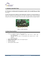
1. GENERAL DESCRIPTION
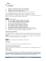
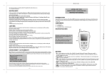
The TCM 130 is a software API for the transceiver module TCM 120 of EnOcean. It enables
the realization of bi-directional RF applications based on the innovative EnOcean radio
technology.
The TCM 120 transceiver module serves the 868 MHz air interface protocol of EnOcean. It
receives all signals of the EnOcean radio transmitters (based on e.g. modules PTM 100,
STM 100) and makes them available via an API. The API provides several hardware
interfaces such as a serial interface, 10bit A/D inputs and digital inputs and digital outputs.
Figure 1: TCM 120 module
1.1 Basic Functionalities
•
•
•
•
•
•
Receive and transmit EnOcean radio telegrams
o All different kinds of telegrams (e.g. PTM 100 or STM 100)
can be generated
o The TCM 130 can send on 128 different IDs (derived from 1 base
number)
o Filter functionality
Serial interface support
Read analog and digital inputs, write digital outputs
EEPROM read/write
Timer functionality
Various power-down modes
©EnOcean GmbH
Page 5 of 30
TCM 130 User Manual V2.04
1.2 Features Overview (based on TCM120 Hardware)
Frequency / modulation type / transmission power: .868.3 MHz / ASK / max. 10 mW
Data rate (transmitter) / channel bandwidth (receiver):............ 120 kbps / 280 kHz
Transmission range: ....................................................................... 300 m free field
Power supply voltage: ......................................................................5V +10%/-5%
Sleep current without BOD and WDT: ................................................ typ. ~0.1 µA1
Sleep current with WDT on, BOD on/off: .................................. typ. ~50µA / 10 µA1
Current consumption (receiver on/off): .............. typ. 33 mA (max. 40 mA) / 15 mA1
Current consumption (receive+transmit): .......................................... max. 55 mA1
Bi-directional serial interface: ..............................full-duplex, async., 9.6 - 57.6 kbps
Receiver features: .................................... sensitivity can be reduced by SW command
Fast power up: .............................................................................................. <1ms
Fast Tx power up from stand-by:................................................................... ~2 µs
Tx/Rx changeover: .................................................................................... ~0.5 µs
Inputs: ..up to 5 inputs, configurable as digital or analog input; AD-conversion up to 10bit
Outputs: .................................................................................up to 5 digital outputs
Free Memory: ................................... 144 bytes EEPROM, ~16 kB FLASH, ~0.5 kB RAM
RSSI Output:................................................... indicates received peak signal strength
BOD = Brown Out Detector, WDT = Watch Dog Timer
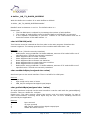
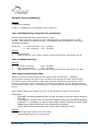
1.3 Physical Dimensions (TCM120 Hardware)
Antenna:........... No antenna installed, 9 cm whip antenna or external antenna mountable
only 1 antenna for transmit and receive
Dimensions of PCB: ..................................... 24.0 x 42.0 x 5 mm (without wiring pins)
Connector: .................................. 16 pins, grid 2.0 mm (4.0 mm in length,
0.5 mm)
1
All input pins connected to GND. All other pins except Vcc, and reset pin not connected
at the time of measurement. All outputs set to 0
©EnOcean GmbH
Page 6 of 30
TCM 130 User Manual V2.04
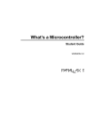
30
2.45
5.5
1.225
Antenna
Pin 2
Pin 20
Pin 1
42
Expansion Port
24
Pin 1
Pin 16
4
2
0.5
Figure 2: TCM 120 package outlines
1.4 Environmental Conditions
Operating temperature: ................................................................ -25 up to +65 °C
Storage temperature: ......................-40 up to +85 °C, +85 up to +100 °C for 1h max.
Humidity:.......................................................................................0 % to 95 % r.h.
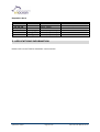
1.5 Ordering Information
Type
EnOcean Ordering Code
TCM 120
TCM 130 Starter Kit
TCM 130 Library CD-ROM
S3003-K120
S3004-K130
S3004-K930
Important note: The expansion port connector, which is mounted for development
purposes on the modules supplied with the TCM 130 Starter Kit ist not mounted on
standard TCM 120 modules. In order to program the TCM 120 modules with own software
it is necessary to contact the programming pins with needles.
©EnOcean GmbH
Page 7 of 30
TCM 130 User Manual V2.04
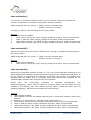
2. FUNCTIONAL DESCRIPTION
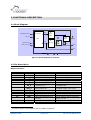
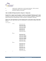
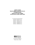
2.1 Block Diagram
10 bit A/D
Analog/Digital IN_0..3
Data
RF
Trans
Transmitter
OUT_0..3
µC
Data
SAW
TxRx
filter
Switch
RF
Recei
Receiver
SER_RX / IN_4
LNA
ver
SER_TX / OUT_4
ANT
RSSI
RxD
RESET
VCC
GND
Figure 3: Block diagram of TCM 120
2.2 Pin Description
Main connector:
Pin No.
1, 16
2
3
4
5
6
7
____________
9
10
11
12
13
RESET
IN_0
IN_1
IN_2
IN_3
SER_RX /
IN_4
SER_TX /
OUT_4
OUT_0
OUT_1
OUT_2
OUT_3
RxD
14
15
RSSI
Vcc
8
1
Symbol
GND
Function
Ground connection
External reset signal
Digital or analog input
Digital or analog input
Digital or analog input
Digital or analog input
Serial communications
reception line
Serial communications
transmission line
Digital output
Digital output
Digital output
Digital output
Raw base band data from
receiver
RSSI signal from receiver
Supply voltage
Operational characteristics
Connect to GND1 if not used
Connect to GND1 if not used
Connect to GND1 if not used
Connect to GND1 if not used
Viewed from TCM
5V CMOS input
Viewed from TCM
5V CMOS output, 20 mA max.
5V CMOS output, 20 mA max.
5V CMOS output, 20 mA max.
5V CMOS output, 20 mA max.
5V CMOS output, 20 mA max.
5V TTL output, source impedance
approx. 11 kΩ
Source impedance approx. 20 kΩ
5V +10%/-5%, max. 55 mA
To reduce power consumption and for stable conditions
©EnOcean GmbH
Page 8 of 30
TCM 130 User Manual V2.04
Expansion Port:
Pin No.
1-11
12, 14, 16
13, 15, 17
18
19
20
Symbol
Reserved
Vcc
GND
_________
MCLR/Vpp
ICSP_DATA
ICSP_CLK
Function
Reserved
Supply voltage
Ground connection
Used for programming
Operational characteristics
5V +10%/-5%, max. 55 mA
Used for programming
Used for programming
3. APPLICATIONS INFORMATION
Please refer to the TCM120 hardware users manual!
©EnOcean GmbH
Page 9 of 30
TCM 130 User Manual V2.04
4. API Description
Important remark: Please note that all interrupts are occupied by the API. If interrupts are
used the API may not work properly!
# define _CONFIG
The first source code line of user application code must contain
#define _CONFIG Code
Through this define the user configures the watch dog timer (WDT) period and brown-out
state. The following table explains the relation between the code and the configuration.
Code
1
2
3
4
5
6
WDT approximate
period (ms)
16
128
2048
16
128
2048
Brown-out state Brown-out voltage(V)
ON
ON
ON
OFF
OFF
OFF
4,2
4,2
4,2
----
The current consumption is much lower without brown out detector (relevant especially
during sleep). For applications using a battery, where fluctuations of the voltage are not
expected it may be helpful to switch off the brown out detector and extend battery life.
Please note: The WDT period strongly depends on temperature. Please refer to the data
sheet of the PIC18F452 micro controller for more details. If not specified _CONFIG 6 is
used.
Important note: It may take up to 60ms until the receiver is stable after a receiverOn(),
repeaterOn() or return from sleep() command. It may happen that during that time the
interrupt routine for receiving is called quite often during that time. In combination with a
WDT period of 16ms this may lead to a repeated reset of the module.
# define _NR_RX_RADIO_BUFFERS
With this define the number of rx radio buffers is defined:
# define _NR_RX_RADIO_BUFFERS NumBuf
NumBuf must be between 4 and 10. The default value is 4.
Please note:
• The free RAM size is reduced by increasing the number of radio buffers.
• The number of radio buffers must be defined before initTCM130() is executed.
©EnOcean GmbH
Page 10 of 30
TCM 130 User Manual V2.04
# define _NR_TX_RADIO_BUFFERS
With this define the number of tx radio buffers is defined:
# define _NR_TX_RADIO_BUFFERS NumBuf
NumBuf must be between 1 and 11. The default value is 1.
Please
•
•
•
note:
The free RAM size is reduced by increasing the number of radio buffers.
The number of radio buffers must be defined before initTCM130() is executed.
If the repeater functionality is used the number of TX radio buffers must be at
least the number of RX radio buffers + 1
char initTCM130(void)
This function must be inserted as first line code in the main program. Initializes the
internal registers. The startup procedure of the module takes less than 1 ms.
Returns:
0
No error. TCM130 correctly initialized
1
Radio buffer wrong initialized: RX buffer address, amount of RX radio buffer out of
specified value. TCM130 not correctly initialized.
2
Reset happened due to stack overflow
3
Reset happened due to stack underflow
4
Reset happened due to Brown-out detection
5
Reset happened due to watch dog timer overflow
6
Reset happened due to power-down
7
Radio buffer wrong initialized: TX buffer address, amount of TX radio buffer out of
specified value. TCM130 not correctly initialized.
char sendSerialByte(unsigned char value)
Send one byte via the serial interface. There is a buffer for 126 bytes.
Returns
0
byte sent
1
byte could not be sent in 20ms
2
SER_RX/TX configured as digital input/output
char getSerialByte(unsigned char *value)
If a byte has been received via the serial interface it can be read with the getSerialByte()
function. There is a buffer for 14 bytes.
Please note: The radio receiver routine has priority over the serial interface. In case of
radio communication incoming serial bytes may be lost. An error handling should be
provided by the application.
Returns
0
1
2
3
©EnOcean GmbH
byte received
no byte received
SER_RX/TX configured as digital output/input
USART RX buffer overrun
Page 11 of 30
TCM 130 User Manual V2.04
4
11
Framing error. Maybe due to serial speed mismatch. Will be cleared
automatically after correct reception of one byte.
parameter address not allowed
char sendSerialTelegram(union telegram *telegram)
The function is used to log the content of received or transmitted telegrams via the serial
interface or to transmit other information via the serial interface. The information is sent
according to the EnOcean serial port protocol. There are several possibilities to address the
bytes in this structure as shown below. There is a buffer for 9 telegrams (126 bytes).
Please note: The transmission of a serial telegram takes at least about 15ms. Please take
care not to enter sleep mode before the transmission of the previous telegram has been
finished.
union telegram{
struct{
unsigned
unsigned
unsigned
unsigned
unsigned
unsigned
unsigned
unsigned
unsigned
unsigned
unsigned
char
char
char
char
char
char
char
char
char
char
char
type;
org;
data3;
data2;
data1;
data0;
id3;
id2;
id1;
id0;
status;
unsigned
unsigned
unsigned
unsigned
unsigned
unsigned
unsigned
unsigned
unsigned
unsigned
unsigned
char
char
char
char
char
char
char
char
char
char
char
type;
org;
mdata5;
mdata4;
mdata3;
mdata2;
mdata1;
mdata0;
mid1;
mid0;
status;
unsigned
unsigned
unsigned
unsigned
unsigned
unsigned
unsigned
unsigned
unsigned
unsigned
unsigned
char
char
char
char
char
char
char
char
char
char
char
type;
org;
: 8;
: 8;
: 8;
: 8;
aid1;
aid0;
: 8;
: 8;
status;
};
struct{
};
struct{
};
};
©EnOcean GmbH
Page 12 of 30
TCM 130 User Manual V2.04
Returns
0
1
2
11
telegram sent
information could not be sent in 20ms
SER_RX/TX configured as digital input/output
parameter address not allowed
Message format
The following figure shows the message format. A data block of length n is composed of 2
synchronization bytes, 1 octet for the header and n-1 octets for the message data.
SER_TX
SER_RX
Sync
Sync
Header
...
Byte0
ByteN-1
Figure 8: Message format for asynchronous serial communication
Octet signals and bit order
•
•
•
Default 9.6 kbps, 8 data bits, no parity bit, one start bit, one stop bit
Line idle is binary 1 (standard)
Each character has one start bit (binary 0), 8 information bits (least significant bit
first) and one stop bit (binary 1)
Byte
SER_TX 5V
SER_RX
STA D0
D1
D2
D3
D4
D5
D6
D7 STOP
0V
Bit
Time
Bit
Time
Bit
Time
Figure 9: Signals and bit order sending a byte
©EnOcean GmbH
Page 13 of 30
TCM 130 User Manual V2.04
Encoding for RPS, 1BS, 4BS,
HRC
0xA5 (sync byte)
0x5A (sync byte)
0x0B (TX_TELEGRAM) 2
0x6B(RX_TELEGRAM)
org
data3
data2
data1
data0
id3
id2
id1
id0
status
ChkSum
General encoding
0xA5 (sync byte)
0x5A (sync byte)
type
org
data3
data2
data1
data0
id3
id2
id1
id0
status
ChkSum
Encoding for 6DT
Encoding for MDA
0xA5 (sync byte)
0x5A (sync byte)
0x0B (TX_TELEGRAM)
0x6B(RX_TELEGRAM)
0x0A
mdata5
mdata4
mdata3
mdata2
mdata1
mdata0
mid1
mid0
status
ChkSum
0xA5 (sync byte)
0x5A (sync byte)
0x0B (TX_TELEGRAM)
0x6B(RX_TELEGRAM)
0x0B
0xXX
0xXX
0xXX
0xXX
aid1
aid0
0xXX
0xXX
status
ChkSum
Remarks
-
type: value 0x0B, and 0x6B may be used, other values reserved for future
data2 = data1 = data0 = 0x00 for RPS,1BS, HRC
Detailed description of ORG field
ORG
0x05
Description
Telegram from a PTM switch module
received (original or repeated message)
1 byte data telegram from a STM sensor
module received
4 byte data telegram from a STM sensor
module received
Telegram from a CTM module received
6byte Modem Telegram
Modem acknowledge telegram
0x06
0x07
0x08
0x0A
0x0B
RRT / TRT Acronym
RPS
1BS
4BS
HRC
6DT
MDA
Description of data0..3 and id0..3
If ORG = 0x05 and NU = 1 (N-message from a PTM switch module)
id3..0
data2..0
data3
32bit transmitter ID
always = 0
as follows:
7
0
RID
UD
RID
UD
PR
SRID
SUD
SA
2
PR
(2
(1
(1
(2
(1
(1
bit)
bit)
bit)
bit)
bit)
bit)
SRID
SUD
SA
Rocker ID, from left (A) to right (D): 0, 1, 2 and 3 (decimal)
UD=1 Æ O-button, UD=0 Æ I-button
PR=1 Æ Button pressed, PR=0 Æ Button released
Second Rocker ID, from left to right: 0, 1, 2 and 3
(Second) SUD=1 Æ Up button, SUD=0 Æ Down button
SA=1 Æ Second action, SA=0 Æ No second action
viewed from TCM module
©EnOcean GmbH
Page 14 of 30
TCM 130 User Manual V2.04
If ORG = 0x05 and NU = 0 (U-message from a PTM switch module)
id3..0
data2..0
data3
32bit transmitter ID
always = 0
as follows:
7
BUTTONS
0
Reserved
PR
BUTTONS
(3 bit)
Number of simultaneously pressed buttons, as following:
PR
Reserved
(1 bit)
(4 bit)
PR = 1 Æ Button pressed, PR = 0 Æ Button released
for future use
PTM 100 (Type1):
0 = 0 Buttons
1 = 2 Buttons
2 = 3 Buttons
3 = 4 Buttons
4 = 5 Buttons
5 = 6 Buttons
6 = 7 Buttons
7 = 8 Buttons
PTM200 (Type2):
0 = 0 Button
1 = not possible
2 = not possible
3 = 3 or 4 buttons
4 = not possible
5 = not possible
6 = not possible
7 = not possible
If ORG = 0x06 (Telegram from a 1 Byte STM sensor)
id3..0
data2..0
data3
32bit transmitter ID
always = 0
Sensor data byte
If ORG = 0x07 (Telegram from a 4 Byte STM sensor)
id3..0
data3
data2
data1
data0
32bit transmitter ID
Value of third sensor analog input
Value of second sensor analog input
Value of first sensor analog input
Sensor digital inputs as follows:
7
Reserved
DI_3
DI_2
DI_1
0
DI_0
If ORG = 0x08 (Telegram from a CTM module set into HRC operation)
id3..0
data2..0
data3
7
RID
32bit transmitter ID
always = 0
as follows:
0
UD
RID
UD
PR
SR
Reserved
PR
SR
(2
(1
(1
(1
(3
bit)
bit)
bit)
bit)
bit)
Reserved
Rocker ID, from left (A) to right (D): 0, 1, 2 and 3
UD=1 Æ O-button, UD=0 Æ I-button
PR=1 Æ Button pushed, PR=0 Æ Button released
SR=1 Æ Store, SR=0 Æ Recall (see note)
for future use
Note: The bit SR is used only when the lower 3 Bits from id0 = B’111’ (scene switch), and RID ≠ 0 (indicates that
the memory buttons M0-M6 are operated in the handheld remote control).
Description of mdata0..5 and mid0..1
If ORG = 0x0A (Modem telegram)
Please note the different structure of modem telegrams with 6 data bytes (mdata0..5) and 2 address bytes
(mid0..1) for the address of the receiving modem.
©EnOcean GmbH
Page 15 of 30
TCM 130 User Manual V2.04
Description of aid0..1
If ORG = 0x0B (Modem Acknowledge telegram)
Please note the different structure of modem acknowledge telegrams with 2 address bytes (aid0..1) for the
address of the answering modem.
Detailed description of STATUS field
If ORG = 0x05 (Telegram from a PTM switch module)
7
Reserved
T21
0
RP_COUNTER
NU
Reserved
T21
(2 bit)
(1 bit)
NU
RP_COUNTER
(1 bit)
(4 bit) =0..15
for future use
T21=0 Æ PTM switch module of type 1,
T21=1 Æ PTM switch module of type 2
NU=1 Æ N-message, NU=0 Æ U-message.
Repeater level: 0 is original message (not repeated)
PTM switch modules of Type 1 (e.g. PTM 100) do not support interpretation of operating more than one rocker at
the same time:
•
N-message received Æ Only one pushbutton was pressed.
•
U-message received Æ No pushbutton was pressed when activating the energy generator, or more than
one pushbutton was pressed.
PTM switch modules of Type 2 allow interpretation of operating two buttons simultaneously:
•
N-message received Æ Only one or two pushbuttons have been pressed.
•
U-message received Æ No pushbutton was pressed when activating the energy generator, or more than
two pushbuttons have been pressed.
Note for telegrams from PTM 100 piezo transmitters: Due to the mechanical hysteresis of the piezo energy bow,
in most rocker switch device implementations, pressing the rocker sends an N-message and releasing the rocker
sends a U-message!
If ORG = 0x06, 0x07, 0x08 or 0x0A (all other telegrams)
7
0
Reserved
Reserved
RP_COUNTER
RP_COUNTER
(4 bit)
(4 bit)
Description of ChkSum
for future use
Repeater level:
0 original message
1 repeated message
Least Significant Byte from addition of all octets except sync bytes and checksum.
The checksum is calculated automatically by the library.
char getRadioTelegram(union telegram *telegram)
When a radio telegram is received the telegram content (11 byte) is stored internally.
There is a buffer for several telegrams. The number of buffers is defined via # define
_NR_RX_RADIO_BUFFERS as described above. The default number of buffers is 4
(maximum value 10). With the function getRadioTelegram() the telegram content is made
available. Identical telegrams arriving within the maturity time of the buffer (default
100ms) are treated as one telegram (typically EnOcean transmitters are repeating the
same message 3 times to improve the transmission probability).
©EnOcean GmbH
Page 16 of 30
TCM 130 User Manual V2.04
Returns
0
1
2
3
4
11
telegram received
telegram filtered.
not received telegram
telegram stored in the last free rx radio buffer
rx radio buffer overflow.
parameter address not allowed
char sendRadioTelegram(union telegram *telegram)
With this command one radio telegram can be transmitted. In order to achieve a high level of
transmission probability it is recommended to send 3 telegrams at random intervals within
40ms. Random intervals can be generated using the pseudo random functions in stdlib.h of
the C18 compiler.
Returns
0
1
2
3
4
11
telegram sent
ID incorrect or data not allowed. Telegram not sent.
ORG byte not allowed. Telegram not sent
telegram couldn’t be sent within 5ms
telegram written in last free tx radio buffer
parameter address not allowed
char setRadioFilter(unsigned long ID)
All received telegrams except modem telegrams will be filtered and all telegrams which do
not stem from the module with the specified ID will be discarded.
Please note: Filtering is done only for the getRadioTelegram() function. The repeater – if
activated - will repeat also telegrams with other IDs.
Returns
0
filter set
char setRadioBufferMaturity(unsigned char time)
With this command the maturity time of the rx radio buffers may be changed. The default
value is 100ms. Identical telegrams arriving within the maturity time are treated as one
telegram. This is necessary because a transmitter usually transmits up to 3 subtelegrams. In addition a repeater may increase this number. 100ms are set as default
value for optimal performance with a repeater. If no repeater is installed or the
transmitter transmits less sub-telegrams the maturity time can be reduced. This may be
helpful in environments with a large number of transmitters.
The value for time must be between 2 and 254 (ms).
©EnOcean GmbH
Page 17 of 30
TCM 130 User Manual V2.04
Returns:
0
Maturity value correctly written.
1
Maturity value correctly written. Value under 100ms.
2
Error code. Maturity value not written. Input value <2ms or >254ms
Error code. Maturity value not written. Value under 60ms not allowed when
3
repeater active
char setSerialSpeed(unsigned char SpeedCode)
With this command the serial speed may be set. The default value is 9600 bit/s.
Code
1
2
3
4
Serial speed (bit/s)
9600
19200
38400
57600
Returns:
0
Serial speed correctly set
1
Error code. Invalid input value.
char clearRadioFilter()
No radio telegram IDs are filtered
Returns
0
filter cleared
char setIDBase(unsigned long IDBase)
With this command the user can rewrite its ID range base number. The information of the
25 most significant bits is stored in EEPROM. This command can only be used a maximum
number of 10 times to avoid misuse. Please note that this command needs ~20ms for
execution. Therefore in _CONFIG 1 and 4 a reset will be performed by the WDT. If one of
these configurations is used please switch off the WDT during execution of this command.
32
0
25 most significant bits
Returns
0
1
2
0
0
0
0
0
0
0
ID range base
new ID base set
ID base < 0xFF800000. ID base not allowed. New ID not set
ID programmed more than 10 times. New ID not set
Important note: When the module is programmed with your application the ID originally
written to the TCM 120 module at production time is erased. The default value of the ID
after programming is “FFFFFF80”. Therefore the ID has to be changed after programming.
It is recommended to read the ID from the TCM 120 module before programming using
the serial interface as described in the TCM 120 user manual and write this ID back to the
module after programming (see Sample 2 in Appendix C).
©EnOcean GmbH
Page 18 of 30
TCM 130 User Manual V2.04
unsigned long readIDBase()
Returns
unsigned long IDBase;
Codes in [0xFF800000, 0xFFFFFFFF] with 7 LSBs to 0
char setRxSensitivity(unsigned char sensitivity)
With this command the TCM radio sensitivity is set.
In LOW radio sensitivity signals from far transmitters are not detected by the TCM
receiver. This feature is useful when only information from transmitters in the vicinity
should be processed.
sensitivity:
Returns
0
1
1 = high sensitivity (typ. –95 dBm)
0 = low sensitivity (typ. –65 dBm)
sensitivity set
radio sensitivity µC pin (RA4) wrongly configured as input. Sensitivity not set
char readRxSensitivity()
Returns
0
1
2
low radio sensitivity
(typ. –65 dBm)
high radio sensitivity
(typ. –95 dBm)
radio sensitivity µC pin (RA4) wrongly configured as input. Sensitivity not read
char sleep(unsigned long time)
Sleep for a time interval specified in WDT period units (as defined in _CONFIG).
The I/O ports maintain the status they had before the Sleep instruction was executed.
For lowest current consumption in this mode, place all I/O pins at either VDD or VSS,
ensure no external circuitry is drawing current from the I/O pin. Pull all I/O pins that are
hi-impedance inputs, high or low externally, to avoid switching currents caused by floating
inputs.
With a signal change on the SER_RX line it is also possible to wake up the module.
Please note:
o If the WDT has been switched off the unit will only wake up with the signal change on
SER_RX!
o If a telegram has been sent via the serial interface using the sendSerialTelegram()
command it is necessary to wait for about 20ms before entering the sleep mode.
Otherwise the serial telegram will not be transmitted completely.
o RX/TX radio buffers are erased by the function before entering in sleep.
Returns:
0
Watch dog timer woke up µC from sleep
1
External signal woke up µC from sleep
©EnOcean GmbH
Page 19 of 30
TCM 130 User Manual V2.04
char receiverOn()
The receiver is switched off after the start-up of the module. With this command the
receiver is switched on, the power consumption strongly increases.
Global unsigned char rec_pdown; /* TRUE if receiver powered down,
FALSE if receiver is running */
The flag rec_pdown is set according to the current status.
Returns
0
radio
1
radio
2
radio
3
radio
radio
4
receiver enabled
receiver control pin (RC0) wrongly configured as input. Action not performed
rx_data pin (RB4) wrongly configured as output. Action not performed
antenna switch 1 pin (RB2) wrongly configured as input. Action not performed
antenna switch 2 pin (RC5) wrongly configured as input. Action not performed
char receiverOff()
With this function the receiver can be switched off. The flag rec_pdown is set according to
the current status.
Global unsigned char rec_pdown; /* TRUE if receiver powered down,
FALSE if receiver is running */
Returns
0
radio receiver disabled
1
radio receiver control pin (RC0) wrongly configured as input. Action not performed
char repeaterOn()
Switches the integrated repeater function on. For a set of sub-telegrams belonging to the
same telegram the repeater functions generates typically three repeated sub-telegrams. If
the air channel is occupied at the moment of sending the number of repeated subtelegrams may be smaller than 3. Telegrams which have already been repeated are not
repeated again. Remote learn telegrams are not repeated!
receiverOn()
command
is
executed
automatically.
The
Please
note:
The
getRadioTelegram() routine must be called on a regular basis! The RX buffers are only
released if the maturity time has elapsed and the buffer content has been read via
getRadioTelegram(). Otherwise the repeater will stop working!
Returns
0 radio repeater enabled
1 radio repeater could not be enabled. Maturity time < 60ms radio repeater could not be
enabled.
2 Number of TX radio buffers < (Number of RX radio buffers+1)
3 radio receiver control pin (RC0) wrongly configured as input. Action not performed
4 radio rx_data pin (RB4) wrongly configured as output. Action not performed
5 radio antenna switch 1 pin (RB2) wrongly configured as input. Action not performed
6 radio antenna switch 2 pin (RC5) wrongly configured as input. Action not performed
©EnOcean GmbH
Page 20 of 30
TCM 130 User Manual V2.04
char repeaterOff()
Switches the integrated repeater function off. The radio reception remains active.
The RX and TX buffers will be cleared.
Returns
0
radio repeater disabled
void reset()
Performs a reset of the module.
char writeOut(unsigned char outPin, unsigned char level)
Set OUT_0 to OUT_4 level as defined in level. The current status is stored in the global
structure output.
char outPin; /* 0 to 4 for OUT_0 to OUT_4 */
char level; /* TRUE=HIGH level, FALSE=LOW level */
global struct out{
unsigned OUT0
unsigned OUT1
unsigned OUT2
unsigned OUT3
unsigned OUT4
unsigned reserved
}output;
:1; /* TRUE=HIGH level, FALSE=LOW level */
:1;
:1;
:1;
:1;
:3;
Returns
0
state written to pin
1
some output pin is configured as input
2
pin value not allowed
3
OUT_4/SER_TX configured as SER_TX
©EnOcean GmbH
Page 21 of 30
TCM 130 User Manual V2.04
char configInputs(unsigned char configCode)
This function configures the TCM130 input pins as analog, digital or reference input. The
table summarizes the available codes and configurations. The default configuration is
0x00. If the SER_RX is configured as IN_4 (configSerialPins) it is always a digital input.
Code
0x00
0x01
0x04
0x05
0x08
0x0D
0x0E
IN_3
A
A
D
D
A
D
D
IN_2 IN_1 IN_0 Vref+ VrefA
A
A
Vdd
Vss
Vref+
A
A
IN_2
Vss
A
D
A
Vdd
Vss
Vref+
D
A
IN_2
Vss
Vref+ VrefA
IN_2 IN_1
Vref+ VrefA
IN_2 IN_1
D
D
D
Vdd
Vss
A: analog input
D: digital input
Vref+/Vref-: reference input
Returns
0
configuration entered
1
configuration code not allowed. Configuration not entered.
char configSerialPins(unsigned char pinConfigCode)
This function is used to configure the TCM130 pin 7 and 8 as serial pins or as digital
input/output. At startup pin7/8 are configured as serial pins.
PinConfigCode =0 : Pin7= IN_4 ; Pin8= OUT_4;
pinConfigCode!=0 : Pin7= SER_RX ; Pin8= SER_TX
Returns
0
1
2
configuration performed.
pin7 IN_4/SER_RX configured wrongly as output
pin8 OUT_4/SER_TX configured wrongly as input
char readADIn(unsigned char inPin, unsigned char resolution, unsigned
int *ADconversion)
Performs a measurement of the voltage at this input (inPin=0..3 for IN_0..3 ) using the
built-in A/D converter with a resolution defined by the parameter resolution (in bit; max.
10 bit) and stores the result in *ADconversion.
Returns
0
A/D process performed
1
analog IN_0 not configured as analogue. A/D not performed
2
analog IN_1 not configured as analogue. A/D not performed
3
analog IN_2 not configured as analogue. A/D not performed
4
analog IN_3 not configured as analogue. A/D not performed
5
inPin value not allowed. A/D not performed
6
analog IN_0 configured as output. A/D not performed
©EnOcean GmbH
Page 22 of 30
TCM 130 User Manual V2.04
7
8
9
10
11
analog IN_1 configured as output. A/D not performed
analog IN_2 configured as output. A/D not performed
analog IN_3 configured as output. A/D not performed
resolution value >10. A/D not performed
address pointed to by 3rd parameter not allowed. A/D not performed
char readDigitalIn(unsigned char inPin, unsigned char *level)
Reads the level of the input pin inPin (inPin =0 for IN_0 .. 4 for IN_4) and stores the
result in *level (TRUE if HIGH level, FALSE if LOW level).
Returns
0
read process correct
1
IN_0 not configured as digital. Reading not performed
2
IN_1 not configured as digital. Reading not performed
3
IN_2 not configured as digital. Reading not performed
4
IN_3 not configured as digital. Reading not performed
5
inPin value not allowed. Reading not performed
6
IN_0 configured as output. Reading not performed
7
IN_1 configured as output. Reading not performed
8
IN_2 configured as output. Reading not performed
9
IN_3 configured as output. Reading not performed
10
IN_4/SER_RX configured wrongly as SER_RX. Reading not performed
11
address pointed to by 2nd parameter not allowed . Reading not performed
12
IN_4/SER_RX configured as output. Reading not performed
unsigned long getTime()
This command returns a time stamp from the internal system clock. The time stamp is
increased every ms (->restart from 0 after about 50 days). During sleep the timer is
stopped.
Please note: During the transmission (also repeating!) and reception of radio telegrams
the timer may be delayed by about 1 ms per telegram.
Returns
Current 32 bit time stamp [0x0-0xFFFFFFFF] in milliseconds
void nop()
Performs a non-instruction cycle. Each nop instruction lasts 100ns.
void wait(unsigned long delay)
Performs a delay of delay milliseconds. A clear watch dog timer is implemented to avoid a
possible reset.
void clrWdt()
Clears the watch dog timer counter. Clear watch dog timer should be used preferably only
once in the program. It should be written in a source code point which is executed on a regular
basis. Not clearing WDT though this instruction within a WDT period provokes a reset of the
TCM130 µC. Only in sleep modus the program can stay longer than the WDT period.
©EnOcean GmbH
Page 23 of 30
TCM 130 User Manual V2.04
void switchWdtOn()
Switches the WDT on. By default the WDT is on (_CONFIG 6).
void switchWdtOff()
Switches the WDT off. This allows saving around 10µA current consumption. If the WDT is
off before going to sleep waking-up is only possible through a hardware signal change on
pin 7 (SER_RX).
char writeEeprom(unsigned char eepromAddress, unsigned char data)
Writes the byte in “data” in the EEPROM address. EEPROM address codes allowed are in
the range [0x50, 0xDF]. Other values out of this range are already used by the library and
are therefore not permitted. It is recommended to read the value in EEPROM after a write
command for verification purposes.
Returns
0
code correctly written in EEPROM
1
address in 1st parameter not allowed
char readEeprom(unsigned char eepromAddress, unsigned char *data)
Reads data from EEPROM address eepromAddress and returns the value in *data.
Returns
0
code correctly read from EEPROM
1
not allowed address code in 1st parameter
11
not allowed address in second parameter
Allocation of variables in RAM
In total about 0.5kB of RAM are available. They are distributed over 2 memory areas.
For a single source code file the compiler is only able to allocate variables in one of these
areas unless the user specifies by using pragmas (outside a function) where the variables
have to be allocated. The largest connected memory area of 336 bytes is “ApplicBank”.
Please use this area for large arrays, strings, unions or structures. If not more than 336
bytes of RAM in total are needed for the application the allocation works automatically.
Example for more allocating more than 336 bytes:
#pragma udata ApplicBank
unsigned char var1[336];
#pragma udata
void main(){
unsigned char var2[10];
…
}
In this case var1 is located in the special area defined as “ApplicBank”, var2 is put into the
other memory section.
For more information please refer to MPLAB® C18 C Compiler User´s Guide.
©EnOcean GmbH
Page 24 of 30
TCM 130 User Manual V2.04
A. Development Tools
A.1 Microchip Tools
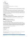
Microchip offers a tool suite for the PIC 18F452 micro controller. EnOcean recommends to
use the following tools:
o
o
o
Microchip MPLAB® ICD 2 in-circuit debugger
Microchip MPLAB® IDE, version 7.3
Please find version 7.3 on the CD-ROM. The license terms and conditions of
Microchip apply! The IDE is also available for free download from
www.microchip.com
Microchip MPLAB® C18 C-Compiler, version 3.0. Please find the full featured 60 day
Student Edition on the CD-ROM. The license terms and conditions of Microchip
apply! The 60-day student edition is also available for free download from
www.microchip.com.
Figure 10: Microchip ICD 2 and MPLAB®
Pin-out of the ICD 2 connector:
Color
1
2
3
4
5
6
Description
Not used
Programming Clock
Programming Data
GND
Vdd
©EnOcean GmbH
1
6
___________
MCLR/Vpp
Page 25 of 30
TCM 130 User Manual V2.04
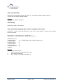
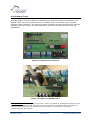
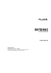
A.2 EnOcean Tools
EnOcean offers a TCM 130 Starter Kit containing an evaluation board, an adapter for the
MPLAB® ICD2 device from Microchip and 2 modified TCM 120 modules3 with mounted
expansion port connector. The evaluation board originally has been developed for use with
RCM110/120 and TCM120. It is also possible to use it for the development of TCM 130
applications.
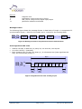
Figure 11: EnOcean EVA 110 board
Figure 12: Adapter for MPLAB® ICD 2
3
Important note: The expansion port connector, which is mounted for development purposes on the
modules supplied with the TCM 130 Starter Kit ist not mounted on standard TCM 120 modules. In
order to program the TCM 120 modules with own software it is necessary to contact the
programming pins with needles.
©EnOcean GmbH
Page 26 of 30
TCM 130 User Manual V2.04
The meaning of connectors, indicators and switches are however different from the
description in the EVA 100 manual.
Description of On-board Connectors
Symbol
Adapter
Function
Female jack for power supply
RCM/TCM
Female header for plug-in RCM or TCM module (Pin
1 is module antenna side)
Test
Connector
Female header connected directly to module leads.
Input IN_0 .. IN_3 are available here.
Vcc
Jack to disconnect the power supply to the inserted
module
GND
GND
Ground connectors for functional control outputs
R0
Operational characteristics
14 - 30 V,
100 mA max.
Bridge
No function
R1
R2
R3
GND
EVG
Functional control outputs directly connected to the
OUT_0..2 output pins of inserted module
GND
PWM
No function
5V CMOS output, 20 mA max.
No function
RS232
DB9 female serial interface connector to PC
•
RCM 120, Operating Mode 0 (Rx)
•
TCM 120 (Rx and Tx)
12 V
TCM RCM
Selector for RCM or TCM module operation
Bridge
Description of On-board Switches
Symbol
MODE
LRN
Function
Switch 1 can be used to reset the module
Switch 2 connected to IN_0. External pull-up needed!
Switch 3 connected to IN_1. External pull-up needed!
Connected to IN_2. External pull-up needed!
SSLM
Connected to IN_3. External pull-up needed!
CLR
Connected to IN_4. External pull-up needed!
Figure 13: External pull-ups
©EnOcean GmbH
Page 27 of 30
TCM 130 User Manual V2.04
Description of On-board Indicators
Symbol
Function
Power
Power supply indicator
Signal indicator
I0
I1
I2
I3
LMI
Indication output of received signal strength of all 868.3 MHz signals (peak
detection)
•
Red: No Radio Signal
•
Yellow: Weak Radio Signal
•
Green 0..2: Strong Radio Signal
Indicator for activity on SER_TX; Status indicator for OUT_4 (inverted status)
Status indicator for OUT_0 .. OUT_2
Please note that the inverted status is shown
(“1” = LED off)
Status indicator for OUT_3 (“1” = LED on)
B. Installation
Install the MPLAB® environment (IDE, C-Compiler and ICD 2)
Unpack the TCM130_Vxxxx.zip in one folder
Copy clib.lib, p18f452.lib and p18f452.h from the installation directory of your
MPLAB® C18 C-compiler to this folder
After that you can start MPLAB® and open the project MyTCM130Project.mcp.
If everything is installed correctly you should now be able to compile the project using
the “Build All” button.
o
o
o
©EnOcean GmbH
Page 28 of 30
TCM 130 User Manual V2.04
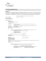
C. Sample Applications
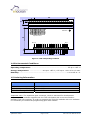
Sample 1
During the first 20s after startup this sample application learns the ID of a PTM 100 switch
and stores it in EEPROM. Afterwards a filter for this ID is set. Every time a telegram from
this switch is received OUT_2 is set if a key is pressed and cleared if the key is released.
#define _CONFIG 3
//Watch dog timer period and brown-out detection configuration
//WDT period ~2s, BOD on
#include "p18f452.h"
#include "TCM130_LIB.h"
#include "TCM130_CFG.h"
void main(void){
unsigned long ID;
union telegram t1;
unsigned char result,id0,id1,id2,id3;
unsigned long time1;
initTCM130();
// TCM130 init function. This function must always be here as first program line. It
// initializes the TCM130.
receiverOn();
// by default receiver is off. Radio receiver functionality is desired radio receive must
// be activated.
setRxSensitivity(0);// Low sensitivity for learn mode
writeOut(3,1);
// LRN mode indicator
time1=getTime();
do{
clrWdt();
//when a PTM radio telegram is received, the information will passed to t1 union.
if(!getRadioTelegram(&t1) &&t1.org==5){
writeEeprom(0x50,t1.id0);
//store ID in EEPROM
writeEeprom(0x51,t1.id1);
writeEeprom(0x52,t1.id2);
writeEeprom(0x53,t1.id3);
break;
//exit LRN mode
}
}while((getTime()-time1)<20000); //end learn mode after 20s
setRxSensitivity(1);
writeOut(3,0);
// LRN mode indicator off
clrWdt();
readEeprom(0x50,&id0);
//read ID from EEPROM
readEeprom(0x51,&id1);
readEeprom(0x52,&id2);
readEeprom(0x53,&id3);
ID=(unsigned long)id0+(unsigned long)id1*0x100+(unsigned long)id2*0x10000+(unsigned long)id3*0x1000000;
clrWdt();
setRadioFilter(ID); // set filter for learned ID
while(1){
clrWdt();
//when a radio telegram is received, the information will passed to t1 union.
if(!getRadioTelegram(&t1)){
//the serial telegram is sent through serial port
t1.type=0x0B;
//this code is part of EnOcean serial protocol.
sendSerialTelegram(&t1);
//radio bytes received are send through the serial port
if (t1.data3&0x10) writeOut(2,1);
//switch output 2 on if key pressed
else writeOut(2,0);
//switch ouput 2 off if key released
}
}
}
©EnOcean GmbH
Page 29 of 30
TCM 130 User Manual V2.04
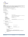
Sample 2
At startup this application checks if already an ID has been programmed (ID different from
FFFFFF80). If the ID has not yet been programmed the application waits for a
SET_IDBASE telegram (TCM 120 User Manual) to change the ID.
If the ID has already been set it is provided via a serial telegram. You can monitor it using
the TCM-Monitor application provided on CD-ROM.
//Watch dog timer period and brown-out detection configuration
#define _CONFIG 3
//WDT period ~2s, BOD on
#include "p18f452.h"
#include "TCM130_LIB.h"
#include "TCM130_CFG.h"
void wait(unsigned long delay);
void checkID(void);
void main(void){
unsigned long ID;
union telegram t1;
unsigned char result;
}
initTCM130();
//TCM 130 init function
checkID();
// Check if ID already programmed. If not wait for serial SET_IDBASE telegram
// with ID as defined in TCM 120 documentation
t1.type=0x0B;
t1.org=0x07;
ID=readIDBase();
t1.id0=ID&255;
t1.id1=(ID/256)&255;
t1.id2=(ID/256/256)&255;
t1.id3=(ID/256/256/256)&255;
sendSerialTelegram(&t1);
wait(20);
//this code is part of EnOcean serial protocol.
//4BS-Telegram
//convert ID into ID bytes 0..3
// send serial telegram with ID
// 20ms delay to make sure telegram is sent before module goes into reset
void wait(unsigned long delay) //delay in ms
{
unsigned long tstart;
tstart=getTime();
do{clrWdt();}while((getTime()-tstart)<delay);
}
void checkID(void){
unsigned long ID,csum;
unsigned char tel[14],i;
}
ID=readIDBase();
if (ID==0xFFFFFF80) {
//ID not yet programmed
do{
clrWdt();
getSerialByte(&tel[0]);
}while(tel[0]!=0xA5);
// wait for sync byte
for (i=1;i<14;i++){
// read serial telegram with 14 bytes
clrWdt();
do{clrWdt();}
while(getSerialByte(&tel[i]));
}
csum=0;
for(i=2;i<13;i++){
csum+=tel[i];}
if ((csum&255)!=tel[13]) reset();
//Perform Reset if Checksum not OK
if ((tel[0]==0xA5)&&(tel[1]==0x5a)&&(tel[2]==0xAB)&&(tel[3]==0x18)){ // SET_IDBASE command?
ID=(unsigned long)tel[7]+(unsigned long)tel[6]*0x100+(unsigned long)tel[5]*0x10000+(unsigned
long)tel[4]*0x1000000;
setIDBase(ID);
}
reset();
}
©EnOcean GmbH
Page 30 of 30
TCM 130 User Manual V2.04