1
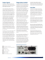
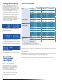
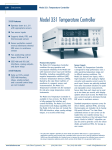
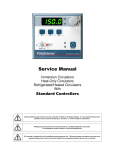
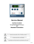
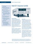
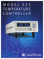
www.lakeshore.com MODEL 335 T E M P E R AT U R E CONTROLLER Model 335 Temperature Controller Operates down to 300 mK with appropriate NTC RTD sensors Two sensor inputs Two configurable PID control loops providing 50 W and 25 W or 75 W and 1 W Autotuning automatically calculates PID parameters Automatically switch sensor inputs using zones to allow continuous measurement and control from 300 mK to 1505 K Custom display set-up allows you to label each sensor input USB and IEEE-488 interfaces Supports diode, RTD, and thermocouple temperature sensors Sensor excitation current reversal eliminates thermal EMF errors for resistance sensors ±10 V analog voltage output, alarms, and relays Introduction Designed with the user and ease of use in mind, the Model 335 temperature controller offers many user-configurable features and advanced functions that until now have been reserved for more expensive, high-end temperature controllers. The Model 335 is the first two-channel temperature controller available with user configurable heater outputs delivering a total of 75 W of low noise heater power—50 W and 25 W, or 75 W and 1 W. With that much heater power packed into an affordable half-rack sized instrument, the Model 335 gives you more power and control than ever. Control outputs are equipped with both hardware and software features allowing you, and not your temperature controller, to easily control your experiments. Output one functions as a current output while output two can be configured in either current or voltage mode. With output two in voltage mode, it functions as a ±10 V analog output while still providing 1 W of heater power and full closed loop proportional-integralderivative (PID) control capability. Alarms and relays are included to help automate secondary control functions. The improved autotuning feature of the Model 335 can be used to automatically calculate PID control parameters, so you spend less time tuning your controller and more time conducting experiments. The Model 335 supports the industry’s most advanced line of cryogenic temperature sensors as manufactured by Lake Shore, including diodes, resistance temperature detectors (RTDs), and thermocouples. The controller’s zone tuning feature allows you to measure and control temperatures seamlessly from 300 mK to over 1,500 K. This feature automatically switches temperature sensor inputs when your temperature range goes beyond the useable range of a given sensor. You’ll never again have to be concerned with temperature sensor over or under errors and measurement continuity issues. The intuitive front panel layout and keypad logic, bright vacuum fluorescent display, and LED indicators enhance the user-friendly front panel interface of the Model 335. Four standard display modes are offered to accommodate different instrument configurations and user preferences. Say goodbye to sticky notes and hand written labels, as the ability to custom label sensor inputs eliminates the guesswork in remembering or determining the location to which a sensor input is associated. These features, combined with USB and IEEE-488 interfaces and intuitive menu structure and logic supports efficiency and ease of use. As a replacement to our popular Model 331 and 332 temperature controllers, the Model 335 offers software emulation modes for literal drop-in compatibility. The commands you are accustomed to sending to the Model 331 and 332 will either be interpreted directly or translated to the most appropriate Model 335 setting. The Model 335 comes standardequipped with all of the functionality of the controllers it replaces, but offers additional features that save you time and money. With the Model 335, you get a temperature controller you control from the world leader in cryogenic thermometry. 2 www.lakeshore.com Lake Shore Cryotronics, Inc. (614) 891-2244 fax: (614) 818-1600 e-mail: [email protected] Sensor Inputs Temperature Control The Model 335 offers two standard sensor inputs that are compatible with diode and RTD temperature sensors. The field-installable Model 3060 option adds thermocouple functionality to both inputs. Providing a total of 75 W of heater power, the Model 335 is the most powerful half rack temperature controller available. Designed to deliver very clean heater power, precise temperature control is ensured throughout your full scale temperature range for excellent measurement reliability, efficiency and throughput. Two independent PID control outputs can be configured to supply 50 W and 25 W or 75 W and 1 W of heater power. Precise control output is calculated based on your temperature setpoint and feedback from the control sensor. Wide tuning parameters accommodate most cryogenic cooling systems and many high-temperature ovens commonly used in laboratories. PID values can be manually set for fine control or the improved autotuning feature can automate the tuning process. Sensor inputs feature a high-resolution 24-bit analog-to-digital converter and each of the two powered outputs function as separate current sources. Both sensor inputs are optically isolated from other circuits to reduce noise and to deliver repeatable sensor measurements. Current reversal eliminates thermal electromagnetic field (EMF) errors in resistance sensors. Ten excitation currents facilitate temperature measurement and control down to 300 mK using appropriate negative temperature coefficient (NTC) RTDs. Autorange mode automatically scales excitation current in NTC RTDs to reduce self heating at low temperatures as sensor resistance changes by many orders of magnitude. Temperatures down to 1.4 K can be measured and controlled using silicon or GaAlAs diodes. Software selects the appropriate excitation current and signal gain levels when the sensor type is entered via the instrument front panel. To increase your productivity, the unique zone setting feature automatically switches sensor inputs, enabling you to measure temperatures from 300 mK to over 1,500 K without interrupting your experiment. The Model 335 includes standard temperature sensor response curves for silicon diodes, platinum RTDs, ruthenium oxide RTDs, and thermocouples. Non-volatile memory can also store up to 39 200-point CalCurves for Lake Shore calibrated temperature sensors or user curves. A built-in SoftCal algorithm can be used to generate curves for silicon diodes and platinum RTDs that can be stored as user curves. Temperature sensor calibration data can be easily loaded into the Model 335 temperature controller and manipulated using the Lake Shore curve handler software program. The Model 335 autotuning method calculates PID parameters and provides feedback to help build zone tables. The setpoint ramp feature provides smooth, continuous setpoint changes and predictable approaches to setpoint without the worry of overshoot or excessive settling times. The instrument’s zone tuning feature automatically switches temperature sensor inputs when your temperature range goes beyond the useable range of a given sensor. This feature combined with the instrument’s ability to scale the sensor excitation through ten pre-loaded current settings allows the Model 335 to provide continuous measurement and control from 300 mK to 1505 K. Both control outputs are variable DC current sources referenced to chassis ground. As a factory default, outputs 1 and 2 provide 50 W and 25 W of continuous power respectively, both to a 50 ) or 25 ) load. For increased functionality, output 2 can also be set to voltage mode. When set to voltage mode, it functions as a ±10 V analog output while still providing 1 W of heater power and full closed loop PID control capability. While in this mode, output 1 can provide up to 75 W of heater power to a 25 ) load. Temperature limit settings for inputs are provided as a safeguard against system damage. Each input is assigned a temperature limit, and if any input exceeds that limit, both control channels are automatically disabled. Interface The Model 335 is standard equipped with universal serial bus (USB) and parallel (IEEE488) interfaces. In addition to gathering data, nearly every function of the instrument can be controlled via computer interface. You can download the Lake Shore curve handler software program to your computer to easily enter and manipulate sensor calibration curves for storage in the instrument’s nonvolatile memory. The USB interface emulates an RS-232C serial port at a fixed 57,600 baud rate, but with the physical plug-ins of a USB. It also allows you to download firmware upgrades, ensuring the most current firmware version is loaded into your instrument without having to physically change your instrument. Both sensor inputs are equipped with a high and low alarm which offers latching and nonlatching operation. The two relays can be used in conjunction with the alarms to alert you of a fault condition and perform simple on-off control. Relays can be assigned to any alarm or operated manually. The ±10 V analog voltage output can be configured to send a voltage proportional to temperature to a strip chart recorder or data acquisition system. You may select the scale and data sent to the output, including temperature or sensor units. Model 335 Rear Panel Connections Sensor input connectors Terminal block (analog outputs/relays) d USB interface e IEEE-488 interface f Line input assembly g Output 2 heater h Output 1 heater i Thermocouple option inputs i f g h b c d e 3 www.lakeshore.com Lake Shore Cryotronics, Inc. (614) 891-2244 fax: (614) 818-1600 e-mail: [email protected] Configurable Display Sensor Selection The Model 335 offers a bright, vacuum fluorescent display that simultaneously displays up to four readings. You can display both control loops, or if you need to monitor just one input, you can display just that one in greater detail. Or you can custom configure each display location to suit your experiment. Data from any input can be assigned to any of the locations, and your choice of temperature sensor units can be displayed. For added convenience, you can also custom label each senor input, eliminating the guesswork in remembering or determining the location to which a sensor input is associated. Sensor Temperature Range (sensors sold separately) Diodes Positive Temperature Coefficient RTDs Negative Temperature Coefficient RTDs Two Input/One Loop Display with Labels Standard display option featuring two inputs and associated outputs. Custom Display with Labels Reading locations can be user configured to accommodate application needs. Here, the input names are shown above the measurement readings along with the designated input letters. Intuitive Menu Structure Logical navigation allows you to spend more time on research and less time on setup. Model 3060 Thermocouple Input Option Thermocouples 3060-F Silicon Diode Silicon Diode Silicon Diode Silicon Diode Silicon Diode Silicon Diode GaAlAs Diode GaAlAs Diode GaAlAs Diode 100 ) Platinum 100 ) Platinum Rhodium-Iron Rhodium-Iron Cernox™ Cernox™ Cernox™ Cernox™ Cernox™ Germanium Germanium Carbon-Glass Carbon-Glass Carbon-Glass Rox™ Rox™ Rox™ Type K Type E ChromelAuFe 0.07% Model DT-670-SD DT-670E-BR DT-414 DT-421 DT-470-SD DT-471-SD TG-120-P TG-120-PL TG-120-SD PT-102/3 PT-111 RF-800-4 RF-100T/U CX-1010 CX-1030-HT CX-1050-HT CX-1070-HT CX-1080-HT GR-300-AA GR-1400-AA CGR-1-500 CGR-1-1000 CGR-1-2000 RX-102 RX-103 RX-202 9006-006 9006-004 9006-002 Useful range 1.4 K to 500 K 30 K to 500 K 1.4 K to 375 K 1.4 K to 325 K 1.4 K to 500 K 10 K to 500 K 1.4 K to 325 K 1.4 K to 325 K 1.4 K to 500 K 14 K to 873 K 14 K to 673 K 1.4 K to 500 K 1.4 K to 325 K 0.3 K to 325 K1 0.3 K to 420 K1, 3 1.4 K to 420 K1 4 K to 420 K1 20 K to 420 K1 0.35 K to 100 K3 1.8 K to 100 K3 1.4 K to 325 K 1.7 K to 325 K2 2 K to 325 K2 0.3 K to 40 K3 1.4 K to 40 K 0.3 K to 40 K3 3.2 K to 1505 K 3.2 K to 934 K 1.2 K to 610 K Magnetic field use T # 60 K & B " 3 T T # 60 K & B " 3 T T # 60 K & B " 3 T T # 60 K & B " 3 T T # 60 K & B " 3 T T # 60 K & B " 3 T T > 4.2 K & B " 5 T T > 4.2 K & B " 5 T T > 4.2 K & B " 5 T T > 40 K & B " 2.5 T T > 40 K & B " 2.5 T T > 77 K & B " 8 T T > 77 K & B " 8 T T > 2 K & B " 19 T T > 2 K & B " 19 T T > 2 K & B " 19 T T > 2 K & B " 19 T T > 2 K & B " 19 T Not Recommended Not Recommended T > 2 K & B " 19 T T > 2 K & B " 19 T T > 2 K & B " 19 T T > 2 K & B " 10 T T > 2 K & B " 10 T T > 2 K & B " 10 T Not Recommended Not Recommended Not Recommended Non-HT version maximum temperature: 325 K Low temperature limited by input resistance range 3 Low temperature specified with self-heating error: ≤ 5 mK 1 2 Silicon diodes are the best choice for general cryogenic use from 1.4 K to above room temperature. Silicon diodes are economical to use because they follow a standard curve and are interchangeable in many applications. They are not suitable for use in ionizing radiation or magnetic fields. Cernox™ thin-film RTDs offer high sensitivity and low magnetic field-induced errors over the 0.3 K to 420 K temperature range. Cernox sensors require calibration. Platinum RTDs offer high uniform sensitivity from 30 K to over 800 K. With excellent reproducibility, they are useful as thermometry standards. They follow a standard curve above 70 K and are interchangeable in many applications. The field installable Model 3060 thermocouple input option adds thermocouple functionality to both inputs. While the option can be easily removed, this is not necessary as the standard inputs remain fully functional when they are not being used to measure thermocouple temperature sensors. Calibration for the option is stored on the card so it can be installed in the field and used with multiple Model 335 temperature controllers without recalibration. 4 www.lakeshore.com Lake Shore Cryotronics, Inc. (614) 891-2244 fax: (614) 818-1600 e-mail: [email protected] Typical Sensor Performance Example Lake Shore sensor Temperature Nominal resistance/ voltage Typical sensor sensitivity4 Measurement resolution: temperature equivalents Electronic accuracy: temperature equivalents Temperature accuracy including electronic accuracy, CalCurve™, and calibrated sensor Electronic control stability5: temperature equivalents Silicon Diode DT-670-CO-13 with 1.4H calibration Silicon Diode DT-470-SD-13 with 1.4H calibration GaAlAs Diode TG-120-SD with 1.4H calibration 1.4 K 77 K 300 K 500 K 1.4 K 77 K 300 K 475 K 1.4 K 77 K 300 K 475 K 30 K 77 K 300 K 500 K 0.3 K 0.5 K 4.2 K 300 K 1.4 K 4.2 K 77 K 420 K 0.35 K 1.4 K 4.2 K 100 K 1.8 K 4.2 K 10 K 100 K 1.4 K 4.2 K 77 K 300 K 0.5 K 1.4 K 4.2 K 40 K 75 K 300 K 600 K 1505 K 1.664 V 1.028 V 0.5597 V 0.0907 V 1.6981 V 1.0203 V 0.5189 V 0.0906 V 5.391 V 1.422 V 0.8978 V 0.3778 V 3.660 ) 20.38 ) 110.35 ) 185.668 ) 2322.4 ) 1248.2 ) 277.32 ) 30.392 ) 26566 ) 3507.2 ) 205.67 ) 45.03 ) 18225 ) 449 ) 94 ) 2.7 ) 15288 ) 1689 ) 253 ) 2.8 ) 103900 ) 584.6 ) 14.33 ) 8.55 ) 3701 ) 2005 ) 1370 ) 1049 ) -5862.9 µV 1075.3 µV 13325 µV 49998.3 µV -12.49 mV/K -1.73 mV/K -2.3 mV/K -2.12 mV/K -13.1 mV/K -1.92 mV/K -2.4 mV/K -2.22 mV/K -97.5 mV/K -1.24 mV/K -2.85 mV/K -3.15 mV/K 0.191 )/K 0.423 )/K 0.387 )/K 0.378 )/K -10785 )/K -2665.2 )/K -32.209 )/K -0.0654 )/K -48449 )/K -1120.8 )/K -2.4116 )/K -0.0829 )/K -193453 )/K -581 )/K -26.6 )/K -0.024 )/K -26868 )/K -862 )/K -62.0 )/K -0.021 )/K -520000 )/K -422.3 )/K -0.098 )/K -0.0094 )/K -5478 )/K -667 )/K -80.3 )/K -1.06 )/K 15.6 µV/K 40.6 µV/K 41.7 µV/K 36.006 µV/K 0.8 mK 5.8 mK 4.4 mK 4.8 mK 0.8 mK 5.2 mK 4.2 mK 4.5 mK 0.2 mK 16 mK 7 mK 6.3 mK 5.3 mK 2.4 mK 2.6 mK 2.7 mK 6 µK 17 µK 62 µK 16 mK 15 µK 152 µK 830 µK 12 mK 3 µK 33 µK 38 µK 8.4 mK 19 µK 62 µK 32 µK 9.6 mK 12 µK 52 µK 2 mK 22 mK 32 µK 90 µK 590 µK 39 mK 26 mK 10 mK 10 mK 12 mK ±13 mK ±76 mK ±47 mK ±40 mK ±13 mK ±69 mK ±45 mK ±38 mK ±7 mK ±180 mK ±60 mK ±38 mK ±13 mK ±10 mK ±39 mK ±60 mK ±0.1 mK ±0.2 mK ±3.8 mK ±339 mK ±0.3 mK ±2.1 mK ±38 mK ±338 mK ±48 µK ±481 µK ±1.8 mK ±152 mK ±302 µK ±900 µK ±1.8 mK ±177 mK ±0.1 mK ±0.8 mK ±108 mK ±760 mK ±0.5 mK ±1.4 mK ±8 mK ±500 mK ±0.25 K7 ±0.038 K7 ±0.184 K7 ±0.73 K7 ±25 mK ±98 mK ±79 mK ±90 mK ±25 mK ±91 mK ±77 mK ±88 mK ±19 mK ±202 mK ±92 mK ±88 mK ±23 mK ±22 mK ±62 mK ±106 mK ±3.6 mK ±4.7 mK ±8.8 mK ±414 mK ±5.3 mK ±7.1 mK ±54 mK ±403 mK ±4.2 mK ±4.7 mK ±6.8 mK ±175 mK ±4.5 mK ±5.1 mK ±6.8 mK ±200 mK ±4.1 mK ±4.8 mK ±133 mK ±865 mK ±5 mK ±6.4 mK ±24 mK ±537 mK Calibration not available from Lake Shore ±1.6 mK ±11.6 mK ±8.8 mK ±9.6 mK ±1.6 mK ±10.4 mK ±8.4 mK ±9 mK ±0.4 mK ±32 mK ±14 mK ±13 mK ±10.6 mK ±4.8 mK ±5.2 mK ±5.4 mK ±12 µK ±34 µK ±124 µK ±32 mK ±30 µK ±304 µK ±1.6 mK ±24 mK ±6 µK ±66µK ±74 µK ±16.8 mK ±38 µK ±124 µK ±64 µK ±19.2 mK ±24 µK ±104 µK ±4 mK ±44 mK ±64 µK ±180 µK ±1.2 mK ±78 mK ±52 mK ±20 mK ±20 mK ±24 mK 100 ) Platinum RTD 500 ) Full Scale PT-103 with 14J calibration Cernox™ CX-1010-SD with 0.3L calibration Cernox™ CX-1050-SD-HT6 with 1.4M calibration Germanium GR-300-AA with 0.3D calibration Germanium GR-1400-AA with 1.4D calibration Carbon-Glass CGR-1-500 with 1.4L calibration Rox™ RX-102A-AA with 0.3B calibration Thermocouple 50 mV 3060 Type K Typical sensor sensitivities were taken from representative calibrations for the sensor listed Control stability of the electronics only, in an ideal thermal system 6 Non-HT version maximum temperature: 325 K 7 Accuracy specification does not include errors from room temperature compensation 4 5 5 www.lakeshore.com Lake Shore Cryotronics, Inc. (614) 891-2244 fax: (614) 818-1600 e-mail: [email protected] Model 335 Specifications Input Specifications Diode PTC RTD NTC RTD 10 mV Thermocouple Sensor temperature coefficient Negative Positive Negative Positive Input range Excitation current Display resolution Measurement resolution Electronic accuracy6 Measurement temperature coefficient Electronic control stability1 0 V to 2.5 V 10 µA ±0.05%2,3 100 µV 10 µV (10 µV + 0.0005% of rdg)/°C ±20 µV 0 V to 10 V 10 µA ±0.05%2,3 100 µV 20 µV (20 µV + 0.0005% of rdg)/°C ±40 µV 0 ) to 10 ) 1 mA4 0.1 m) 0.2 m) (0.01 m) + 0.001% of rdg)/°C ±0.4 m) 0 ) to 30 ) 1 mA4 0.1 m) 0.2 m) (0.03 m) + 0.001% of rdg)/°C ±0.4 m) 0 ) to 100 ) 4 1 mA 1 m) 2 m) (0.1 m) + 0.001% of rdg)/°C ±4 m) 0 ) to 300 ) 1 mA4 1 m) 2 m) (0.3 m) + 0.001% of rdg)/°C ±4 m) 0 ) to 1 k) 4 1 mA 10 m) 20 m) (1 m) + 0.001% of rdg)/°C ±40 m) 0 ) to 3 k) 1 mA4 10 m) 20 m) (3 m) + 0.001% of rdg)/°C ±40 m) 0 ) to 10 k) 1 mA4 100 m) 200 m) (10 m) + 0.001% of rdg)/°C ±400 m) 0 ) to 10 ) 1 mA4 0.1 m) 0.15 m) (0.01 m) + 0.001% of rdg)/°C ±0.3 m) 0 ) to 30 ) 300 µA4 0.1 m) 0.45 m) (0.03 m) + 0.0015% of rdg)/°C ±0.9 m) 0 ) to 100 ) 100 µA4 1 m) 1.5 m) (0.1 m) + 0.001% of rdg)/°C ±3 m) 0 ) to 300 ) 30 µA4 1 m) 4.5 m) (0.3 m) + 0.0015% of rdg)/°C ±9 m) 0 ) to 1 k) 10 µA4 10 m) (1 m) + 0.001% of rdg)/°C 0 ) to 3 k) 3 µA4 10 m) 0 ) to 10 k) 1 µA4 100 m) 0 ) to 30 k) 300 nA4 100 m) 0 ) to 100 k) 100 nA4 1) (100 m) + 0.002% of rdg)/°C ±30 m) ±0.004% of rdg ±90 m) ±0.004% of rdg ±300 m) ±0.004% of rdg ±900 m) ±0.004% of rdg ±3 ) ±0.01% of rdg ±50 mV NA 0.1 µV 15 m) +0.002% of rdg 45 m) +0.002% of rdg 150 m) +0.002% of rdg 450 m) +0.002% of rdg 1.5 ) +0.005% of rdg 0.4 µV ±80 µV ±0.005% of rdg ±80 µV ±0.01% of rdg ±0.002 ) ±0.01% of rdg ±0.002 ) ±0.01% of rdg ±0.004 ) ±0.01% of rdg ±0.004 ) ±0.01% of rdg ±0.04 ) ±0.02% of rdg ±0.04 ) ±0.02% of rdg ±0.4 ) ±0.02% of rdg ±0.002 ) ±0.06% of rdg ±0.002 ) ±0.06% of rdg ±0.01 ) ±0.04% of rdg ±0.01 ) ±0.04% of rdg ±0.1 ) ±0.04% of rdg ±0.1 ) ±0.04% of rdg ±1.0 ) ±0.04% of rdg ±2.0 ) ±0.04% of rdg ±10.0 ) ±0.04% of rdg ±1 µV ±0.05% of rdg5 (0.1 µV + 0.001% of rdg)/°C ±0.8 µV (3 m) + 0.0015% of rdg)/°C (10 m) + 0.001% of rdg)/°C (30 m) + 0.0015% of rdg)/°C Control stability of the electronics only, in ideal thermal system Current source error has negligible effect on measurement accuracy 3 Diode input excitation can be set to 1 mA 4 Current source error is removed during calibration 5 Accuracy specification does not include errors from room temperature compensation 6 Accuracy at Tcal, typically 23.5 °C ±1.5 °C 1 2 Sensor Input Configuration Measurement type Excitation Supported sensors Standard curves Input connector Diode/RTD 4-lead differential Constant current with current reversal for RTDs Diodes: Silicon, GaAlAs RTDs: 100 ) Platinum, 1000 ) Platinum, Germanium, Carbon-Glass, Cernox™, and Rox™ DT-470, DT-670, DT-500-D, DT-500-E1, PT-100, PT-1000, RX-102A, RX-202A 6-pin DIN Thermometry Thermocouple 2-lead differential, room temperature compensated NA Most thermocouple types Type E, Type K, Type T, AuFe 0.07% vs. Cr, AuFe 0.03% vs. Cr Screw terminals in a ceramic isothermal block Number of inputs2 Input configuration Inputs can be configured from the front panel to accept any of the supported input types. Thermocouple inputs require an optional input card that can be installed in the field. Once installed the thermocouple input can be selected from the front panel like any other input type. Isolation Sensor inputs optically isolated from other circuits but not each other A/D resolution24-bit Input accuracy Sensor dependent, refer to Input Specifications table Measurement resolution Sensor dependent, refer to Input Specifications table Maximum update rate 10 rdg/s on each input, 5 rdg/s when configured as 100 k) NTC RTD with reversal on Autorange Automatically selects appropriate NTC RTD or PTC RTD range User curves Room for 39 200-point CalCurves™ or user curves SoftCal™ Improves accuracy of DT-470 diode to ±0.25 K from 30 K to 375 K; improves accuracy of platinum RTDs to ±0.25 K from 70 K to 325 K; stored as user curves Math Maximum and minimum Filter Averages 2 to 64 input readings 6 www.lakeshore.com Lake Shore Cryotronics, Inc. (614) 891-2244 fax: (614) 818-1600 e-mail: [email protected] Control Front Panel Control outputs2 Display Heater outputs Number of reading displays Display units Reading source Display update rate Temperature display resolution Control type Closed loop digital PID with manual heater output or open loop; warm up mode (output 2 only) Update rate10/s Tuning Autotune (one loop at a time), PID, PID zones Control stability Sensor dependent, see Input Specifications table PID control settings Proportional (gain) 0 to 1000 with 0.1 setting resolution Integral (reset) 1 to 1000 (1000/s) with 0.1 setting resolution Derivative (rate) 1 to 200% with 1% resolution Manual output 0 to 100% with 0.01% setting resolution Zone control 10 temperature zones with P, I, D, manual heater out, heater range, control channel, ramp rate Setpoint ramping 0.1 K/min to 100 K/min Output 1 Type Control modes D/A resolution Max power Max current Voltage compliance (min) Heater load for max power Heater load range Ranges Heater noise Heater connector Grounding Safety limits Variable DC current source Closed loop digital PID with manual output or open loop 16-bit 25 ) setting 50 ) setting 75 W* 50 W 50 W 1.73 A 1.41 A 1A 43.3 V 35.4 V 50 V 25 ) 25 ) 50 ) 10 ) to 100 ) 3 (decade steps in power) 0.12 µA RMS (dominated by line frequency and its harmonics) Dual banana Output referenced to chassis ground Curve temperature, power up heater off, short circuit protection *75 W only available when output 2 is in voltage mode Output 2 Type Control modes D/A resolution Max power Max current Voltage compliance (min) Heater load for max power Heater load range Ranges Heater noise Heater connector Grounding Safety limits Variable DC current source or voltage source Current mode Voltage mode Closed loop digital PID with Closed loop digital PID with manual output, zone, open loop manual output, zone, open loop, warm up, monitor out 15-bit 16-bit (bipolar)/15-bit (unipolar) 25 ) setting 50 ) setting N/A 25 W 25 W 1W 1A 0.71 A 100 mA 25 V 35.4 V ±10 V 25 ) 50 ) 100 ) 10 ) to 100 ) 100 ) min (short circuit protected) 3 (decade steps in power) N/A 0.12 µA RMS 0.3 mV RMS Dual banana Detachable terminal block Output referenced to chassis ground Curve temperature, power up heater off, short circuit protection Warm up heater mode settings (output 2 only) Warm up percentage 0 to 100% with 1% resolution Warm up mode Continuous control or auto-off Monitor output settings (output 2 voltage only) Scale User selected Data source Temperature or sensor units Settings Input, source, top of scale, bottom of scale, or manual Update rate10/s Range ±10 V Resolution 16-bit, 0.3 mV Accuracy ±2.5 mV Noise 0.3 mV RMS Minimum load resistance100 ) (short-circuit protected) Connector Detachable terminal block Sensor units display resolution Other displays 2-line by 20-character, 9 mm character height, vacuum fluorescent display 1 to 4 K, °C, V, mV, ) Temperature, sensor units, max, and min 2 rdg/s 0.001° from 0° to 99.999°, 0.01° from 100° to 999.99°, 0.1° above 1000° Sensor dependent, to 5 digits Sensor name, setpoint, heater range, heater output, and PID Setpoint setting resolution Same as display resolution (actual resolution is sensor dependent) Heater output displayNumeric display in percent of full scale for power or current Heater output resolution 1% Display annunciators Control input, alarm, tuning LED annunciators Remote, alarm, control outputs Keypad 25-key silicone elastomer keypad Front panel features Front panel curve entry, display brightness control, and keypad lock-out Interface IEEE-488.2 Capabilities SH1, AH1, T5, L4, SR1, RL1, PP0, DC1, DT0, C0, E1 Reading rate To 10 rdg/s on each input Software support LabVIEW™ driver (contact Lake Shore for availability) USB Function Emulates a standard RS-232 serial port Baud rate57,600 Connector B-type USB connector Reading rate To 10 rdg/s on each input Software support LabVIEW™ driver (contact Lake Shore for availability) Special interface features Model 331/332 command emulation mode Alarms Number Data source Settings 2, high and low for each input Temperature or sensor units Source, high setpoint, low setpoint, deadband, latching or non-latching, audible on/off, and visible on/ off Display annunciator, beeper, and relays Actuators Relays Number2 Contacts Normally open (NO), normally closed (NC), and common (C) Contact rating 30 VDC at 3 A Operation Activate relays on high, low, or both alarms for any input, or manual mode Connector Detachable terminal block General Ambient temperature15 °C to 35 °C at rated specifications; 5 °C to 40 °C at reduced specifications Power requirement 100, 120, 220, 240 VAC, ±10%, 50 or 60 Hz, 210 VA Size 217 mm W × 90 mm H × 317 mm D (8.5 in × 3.5 in × 14.5 in), half rack Weight 7.6 kg (16.8 lb) Approval CE mark 7 www.lakeshore.com Lake Shore Cryotronics, Inc. (614) 891-2244 fax: (614) 818-1600 e-mail: [email protected] Lake Shore Cryotronics, Inc. 575 McCorkle Boulevard Westerville, OH 43082-8888 USA Tel 614-891-2244 Fax 614-818-1600 e-mail [email protected] www.lakeshore.com Ordering Information Part number 335 3060-H Established in 1968, Lake Shore Cryotronics, Inc. is an international leader in developing innovative measurement and control solutions. Founded by Dr. John M. Swartz, a former professor of electrical engineering at the Ohio State University, and his brother David, Lake Shore produces equipment for the measurement of cryogenic temperatures, magnetic fields, and the characterization of the physical proper ties of materials in temperature and magnetic environments. Description 2 diode/RTD inputs and 2 control outputs 2-thermocouple input option for Model 335 Specify line power option* VAC-100 Instrument configured for 100 VAC with U.S. power cord VAC-120 Instrument configured for 120 VAC with U.S. power cord VAC-120-ALL Instrument configured for 120 VAC with U.S. power cord and universal Euro line cord and fuses for 220/240 VAC setting VAC-220 Instrument configured for 220 VAC with universal Euro line cord VAC-240 Instrument configured for 240 VAC with universal Euro line cord *Other country line cords available, consult Lake Shore Accessories included 106-009 G-106-233 G-106-773 —— MAN-335 Heater output connector (dual banana jack) Sensor input mating connector (6-pin DIN plug); 2 included Terminal block, 8-pin Calibration certificate Model 335 user manual Accessories available 6201 8001-335 CAL-335-CERT CAL-335-DATA 112-177 112-178 1 m (3.3 ft long) IEEE-488 (GPIB) computer interface cable assembly CalCurve™, factory installed – the breakpoint table from a calibrated sensor stored in the instrument (extra charge for additional sensor curves) Instrument recalibration with certificate Instrument recalibration with certificate and data Cable assembly for 2 sensors and 2 heaters (335), 10 ft Cable assembly for 2 sensors and 2 heaters (335), 20 ft All specifications are subject to change without notice 031611