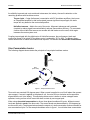
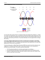
1
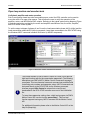
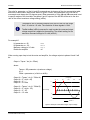
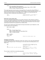
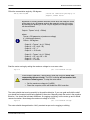
Brushless AC Motor Commutation
Sinusoidal Commutation with a PC based Motion Controller
Application Note
AN1004
Precision MicroControl Corporation
2075-N Corte del Nogal
Carlsbad, CA 92009-1415 USA
Tel: (760) 930-0101
Fax: (760) 930-0222
Information: [email protected]
Technical Support: [email protected]
AN1004
Brushless AC Motor Commutation
Table of Contents
First a little history................................................................................................................................ 3
Sine Commutation basics .................................................................................................................... 4
PMC’s Sine Commutation Solution ...................................................................................................... 6
System Requirements ......................................................................................................................... 8
Defining the commutation parameters ............................................................................................... 13
Initialize the commutation and start closed loop motion ..................................................................... 18
Index ................................................................................................................................................. 20
List of Figures
Figure 1: Simple brushless motor ......................................................................................................4
Figure 2: Sine Commutation waveforms ............................................................................................5
Figure 3: DCX-AT300 motion Control Motherboard ...........................................................................6
Figure 4: DCX-MC320 sine commutation servo control module.........................................................6
Figure 5: DCX-BF320 interconnect card ............................................................................................6
Figure 6: Typical system interconnect diagram ..................................................................................7
Figure 7: WinControl – MCCL command user interface .....................................................................9
Figure 8: Example commutation angle / output voltage.....................................................................10
Figure 9: Linear motor diagram.........................................................................................................12
Figure 10: Commutation circuit block diagram ..................................................................................17
Figure 11: Servo Tuning program .....................................................................................................19
Precision MicroControl Corp.
2
AN1004
Brushless AC Motor Commutation
Brushless AC Motor Commutation
Sinusoidal Commutation with a PC based Motion Controller
First a little history
For years the brush type permanent magnet motor has been successfully used in a wide range of
motion control applications. Relatively low cost and easy to manufacture, brush type motors still
account for the majority of servo motor sales worldwide. But the brush motor does have it limitations:
•
•
•
•
High inertia to torque ratio reduces maximum velocity and acceleration
High maintenance
Limited ability to dissipate heat causes bearing failure resulting in motor failure
Arcing of brushes causes electrical and audible noise
Fueled by technology advancements in the aerospace and defense industries in the 70’s and 80’s,
two milestone events paved the way for acceptance of brushless motors for industrial applications:
The development of high energy, rare earth magnets which reduced motor size/weight and
significantly increased motor velocities
Power MOSFET’s (and later IGBT’s) allowed brushless motor amplifiers to overcome
switching latency and heat buildup to reliably drive motors using a wide range of supply
voltages
In the early to mid 1990’s the mantra was ‘smaller, faster, cheaper’, and the brushless motor/amplifier
industry took it to heart. Now the servo engineer could reap the benefits of brushless motors without
obliterating project budgets. What they got with the new breed of DC brushless motors was:
•
•
•
•
•
Higher performance - Low rotor inertia results in higher velocity and acceleration
High reliability and low maintenance - no brushes to wear out
Superior heat dissipation - coils are mounted in a heat sink (stator)
Reduced EMI emissions - No brush to commutator arcing
High power to size ratio
Precision MicroControl Corp.
3
AN1004
Brushless AC Motor Commutation
As reliability improved and costs continued to decrease, the industry focused its attention on the
remaining problems with brushless motors:
Torque ripple – 6 step (hall-sensor) commutation with DC brushless amplifiers (also known
as Trapezoidal amplifiers or hall commutated) causes significant torque ripple, the static
torque will vary based on the motor shaft position.
Hall-effect sensors – Add to the cost of the motor. Alignment tolerances and hysteresis
(required to reduce signal bounce/oscillation) reduces commutation efficiency. To commutate
a motor without Hall-effect sensors an encoder with hall tracks must be used, which again
increases the motor system cost.
Coupling torque ripple with the deficiencies of Hall-effect sensors, the performance (static and
continuous torque) of a typical DC brushless motor is reduced by 15% to 20%. To address these
issues another form of motor commutation was required. The answer was Sinusoidal Commutation.
Sine Commutation basics
The following diagram demonstrates the principals of very simple brushless motors:
Coil
(phase U)
Rotor
(motor shaft)
A
D
B
C
E
Coil
(phase W)
Coil
(phase V)
Magnet
Figure 1: Simple brushless motor
Three coils are mounted 120 degrees apart. When current is applied to a coil it will attract the nearest
rotor magnet. If current is applied to the phase U coil, the rotor will turn clockwise until magnet A is
aligned with the coil (at a detent). This simple brushless motor is similar to a how a stepper motor
operates, turning on one coil will cause the shaft to rotate by one magnet pole.
When using sinusoidal commutation to drive a three phase brushless AC motor, different current
levels are applied to each of the three coils. The current levels are phase shifted by 120 degrees (as
are the motor coils). The diagram below shows the outputs of a sine commutation motion controller for
one commutation cycle. For the example brushless motor in figure 1, it would take three commutation
Precision MicroControl Corp.
4
AN1004
Brushless AC Motor Commutation
cycles to complete one rotation of the motor shaft.
Rotor Angle
(in degrees)
0
30
60
90
120
Commutation Angle
(in degrees)
0
90
180
270
360
Phase U
Phase V
Phase W
Figure 2: Sine commutation waveforms
You may notice that in figure 2 there is no reference made to the voltage level of phases U, V, and W.
The velocity of a brushless AC motor is controlled by the amplitude (peak to peak voltage level) of the
sine output. The greater the amplitude of the sine waves, the more current flows through the coils, the
greater the torque (velocity) of the motor. The phase relationship of the sine signals does not change
with velocity.
In the past, ‘intelligent’ digital drives were required to provide the sine commutation. These digital
drives coupled sophisticated digital electronics for sine commutation and feedback loops, with high
power PWM amplifier circuitry. The resulting system performance was impressive but for many OEM
applications the cost per axis was prohibitive.
Over the last few years, as Digital Signal Processors (DSP) have revolutionized the architecture and
capabilities of PC based motion control cards, a cost effective solution for sine commutation of
brushless motors has emerged. This solution has three main benefits:
•
•
•
The PC provides the platform for developing sophisticated user interfaces
Low cost Sinusoidal (three phase current mode) amplifiers provide the PWM drive current
Powerful PC based motion control cards tightly integrate trajectory planning, feedback loops,
and sine commutation control signals
Precision MicroControl Corp.
5
AN1004
Brushless AC Motor Commutation
PMC’s Sine Commutation Solution
PMC’s DCX-AT300 Modular Motion Control System provides the OEM machine builder with a
powerful and flexible control system for brushless AC servo applications. This system combines a
RISC processor based motion control motherboard (DCX-AT300)
intel
i960
ispl1032
Lattice
Figure 3: DCX-AT300 motion control motherboard
with one or more 40 MHz TI 32054 DSP, Dual DAC, DCX-MC320 motion control modules.
1
25
1
26
2
JP1
1
JP2
1
DCX-MC320
JP3
Figure 4: DCX-MC320 – sine commutation servo control module
Each DCX-MC320 Sine Commutation module provides both U and V phase outputs for controlling
the motion of one brushless AC servo. As many as six DCX-MC320’s can be installed on a single
DCX-AT300 motion control motherboard, allowing the user to simultaneously control six axes.
The DCX-MC320 uses a high density FPGA to implement a high speed hardware sine lookup table. A
hardware sine commutation table results in the phase U and V DAC outputs being updated at a
frequency of 300KHz. This is a significant improvement over traditional software based sine
commutation, which is limited to the frequency of the servo loop, typically 2KHz to 20 KHz.
To simply system wiring an optional DIN rail mounted interconnect card (DCX-BF320) is available.
J1
DCX-BF320
REV. A
PMC CORP.
TO MC320
TS2
SHLD
GND
Phase W
Phase V
+5
PWR
Hall #3
Hall #2
Hall #1
SHLD
GND
PWR
ZZ+
BB+
AA+
TS1
PRIMARY ENCODER
TS3
SHIELD
Phase U
RETURN
SHIELD
DIR'N
ENABLE
RETURN
FAULT
RETURN
COARSE
RETURN
LIM POS
LIM NEG
RETURN
Figure 5: DCX-BF320 interconnect card
A typical single axis system interconnect diagram is shown on the next page.
Precision MicroControl Corp.
6
AN1004
Brushless AC Motor Commutation
Sinusoidal AC
Brushless Servo Amplifier
AC Brushless Motor
W Ref (optional)
Phase U
V Ref (DAC 2)
Phase V
U Ref (DAC 1)
Phase W
TO MC320
DCX-BF320
REV. A
PMC CORP.
J1
Ref SHLD
GND
W
V
+5
PWR
Hall #3
Hall #2
Hall #1
Case Gnd
SHIELD
Phase U
RETURN
Amp. Enable
SHIELD
DIR'N
ENABLE
Amp. Fault
Motor Temp
RETURN
FAULT
SHLD
GND
PWR
ZZ+
BB+
AA+
Gnd
RETURN
COARSE
RETURN
LIM POS
LIM NEG
RETURN
Hall Sensors / Encoder Hall Tracks (optional)
Encoder signals (A, B, & Z)
DCX-AT300
Ver. ___ Rev. ___
DCX-AT300
Ver. ___ Rev. ___
intel
i960
DCX-MC320
ispl1032
Lattice
Figure 6: Typical system interconnect diagram
Precision MicroControl Corp.
7
AN1004
Brushless AC Motor Commutation
System Requirements
The following components are required to provide sinusoidal commutation for one or more axes:
PC computer – Platform for the user’s application program and PMC software/tools
Motion Control Application Programming Interface (MCAPI) – PMC’s motion control
software and programming tools for WIndows NT/98/95
Motion Integrator – PMC’s system integration, diagnostics, and servo tuning suite of tools
DCX-AT300 – PMC motion control motherboard (supports 1 to 6 axes)
DCX-MC320 – Sine commutation servo control module (1 per axis)
DCX-BF320 (optional) – Interconnect breakout (1 per axis)
Sinusoidal Brushless Amplifier – 1 per axis. A partial listing of suppliers includes:
• Advanced Motion Control
www.a-m-c.com
• Copley Controls
www.copleycontrols.com
• Elmo Motion Control
www.elmomc.com
• Glentek
www.glentek.com
• Servo Dynamics
www.servodynamics.com
Motor – Three phase AC brushless motor with incremental encoder or Linear AC motor with
incremental encoder. Hall-effect sensors or encoder hall track recommended (required for
pending auto commutation initialization feature)
Axis I/O (optional) – Travel Limit inputs (+/-, opto isolated, +12V to +24V), Coarse Home
input (opto isolated, +12V to +24V), Amplifier Fault input (opto isolated, +12V to +24V),
Amplifier Enable output (open collector, +5V to +24V)
Precision MicroControl Corp.
8
AN1004
Brushless AC Motor Commutation
Open loop motion and encoder tests
Verify basic amplifier and motor operation
Prior to configuring closed loop sine commutation servo control the DCX controller can be used to
move the motor in an open loop manner. This will allow the user to verify the operation of the
amplifier, motor, and MC320 dual DAC outputs. Referring to the typical system wiring diagram (Figure
6) and documentation provided by the motor and amplifier manufacturer wire; the motor, amplifier,
and DCX motion control system.
To set the output voltages of phases U and V use the Load commutation phase shift A (aLAn) and the
Load commutation phase shift B (aLAn) commands. Issue these commands to the DCX-AT300 using
the Windows MCCL command interface WinControl (a MCAPI component).
Figure 7: WinControl – MCCL command user interface
i
The current release of PMC’s Motion Control API does yet not provide
high level function calls for the commutation parameters. The following
descriptions use PMC’s MCCL (Motion Control Command Language)
commands. This two character mnemonic command set provides fields
for defining axis numbers and parameter values. MCCL commands can
be issued directly to the DCX-AT300 via the Windows command
interface program Win Control or entered into a text file and
downloaded to the DCX-AT300 controller as a part of the initialization
file.
To issue these parameter settings from a high level program via PMC’s
Motion Control API use the function pmccmdex( ). This low level
function supports issuing any MCCL command via the Motion Control
API.
For additional information please refer to the Motion Control API on line
help file (Mcapi.hlp).
Precision MicroControl Corp.
9
AN1004
Brushless AC Motor Commutation
The units for parameter n of the LA and LB commands are in degrees of the sine commutation table,
and like the commutation wave forms shown in figures 2 and 8, the parameters of the LA and LB
commands must always be 120 degrees apart. When parameter n of the LA and LB commands is set
to specific angles of the sine table, the phase U and V outputs of the MC320 will be set to the sine
ratio of the current maximum voltage setting (aSQn).
The phase U and V command outputs from the DCX-MC320 can range
from –10 volts to +10 volts. The resolution of these signals is 16 bit.
i
The Set torQue (aSQn) command is used to scale the command output
voltage range that is applied to the amplifier. The default setting for the
maximum command voltage is 10 volts (aSQ10 ).
For example if:
LA parameter n = 90
LB parameter n = -30
Maximum voltage is 2.0 volts
Enable the amplifier
1LA90
1LB-30
1SQ2.0
1MN
When running open loop to test the motor and amplifier, the voltage outputs to phases U and V will
be:
Output = Tqmax * sin (θ + Offset)
where:
Tqmax = SQ parameter n (maximum voltage)
θ=0
Offset = parameter n (of aLAn or aLBn)
Commutation Angle
(in degrees)
Output U = Tqmax * sin (θ * Offset A)
Output U = 2 * sin(θ + 90)
Output U = 2 * 1
Output U = 2.0 volts
Output V = Tqmax * sin (θ * Offset B)
Output V = 2 * sin(θ + -30)
Output V = 2 * -0.5
Output V = 1.0 volts
-30 0
90
180
270
360
2V
1V
Output Voltage
-1V
-2V
Phase U
Figure 8: Example commutation angle / output voltage
Precision MicroControl Corp.
10
AN1004
Brushless AC Motor Commutation
Setting the MC320 phase U and V outputs to non-zero values (with the aLAn and aLBn commands)
should cause the amplifier to apply current to the motor windings, causing the motor to move a detent
position.
i
A detent is one of the many locations where a motor magnet and the
motor coils are aligned.
* For this example the maximum voltage output was set to 2.0 volts. For some
motor/amplifier combinations this may be more than enough, for others the
maximum command voltage may need to be as high as 10 volts.
!
Start with a SQ setting of 1 volt (aSQ1), if the motor moves and then resists
attempts at manual repositioning (before the Wait two seconds command times
out) then there is no need to apply a higher voltage to the coils. If when manual
force is applied the motor does not return to its position the maximum output
voltage (SQ parameter n) should be increased.
Don’t get in a hurry and set the maximum voltage too high. Besides possibly
ripping your fingers off, applying high current to the coils for an extended period of
time may cause damage to the motor.
After the motor moves, set the outputs to 0.0 volts by issuing the Set torQue command with parameter
n = 0.
1SQ0
If the motor doesn’t move the possible reasons include:
Amplifier not enabled
Amplifier Fault (under voltage, over voltage, over temperature, over current, etc.)
Improper connections
Detent Test
The can be used to verify proper connections and operation of the amplifier and motor:
1SQ0
1QM
AL0,AR100
AL-120,AR101
AL15,AR102
AL1,AR103
AL23,AR104
AL0,AR105
;set maximum voltage to 0.0 volts
;configure axis for Torque Mode
;aLAn register
;aLBn register
;detent increment register
;maximum voltage (aSQn) register
;set macro 100 repeat count
;clear Detent Test loop counter
WA1
;wait one second
MD100,1MN,1LA@100,1LB@101,1SQ@103,WA.5,1TP,MJ101
;set phase U and V outputs
Precision MicroControl Corp.
11
AN1004
Brushless AC Motor Commutation
MD101,AL@100,AA@102,AR100,AL@101,AA@102,AR101,1SQ0,MJ102
;increase LA and LB by 15 degrees
MD102,AL@105,AA1,AR105,IG@104,BK,NO,MJ100
;increment Detent Test loop counter
Issuing the command Macro Call 100 (MC100) will start the motor rotating through one commutation
cycle (1/3 of a rotation of a rotary motor). To cause a rotary motor to complete one full revolution,
increase the repeat count in stored in register 104 to 72 (AL72,AR104). If the motor does not move,
increase the maximum voltage (torque) that is set by the sequence AL1,AR103. If the motor does not
move after the maximum voltage has been increased to 5 volts contact PMC Tech Support.
i
This Detent Test is similar to a DC voltage step response that is typically
used to tune/setup a DC brushless or brush amplifier.
Encoder operation during Detent Test
During the Detent Test, as the motor moves, the encoder should increment. In other words the
reported position should be larger at the end of the test than at the beginning. Looking at macro 100
of the Detent Test, after the first move, the position of the encoder is reported (1TP). An updated
encoder position will be is reported after every step voltage (detent search) change.
If the motor moves but the reported encoder position does not change there is a problem with either
the encoder or the encoder decode circuitry of the MC320 module. Use an oscilloscope to verify
proper operation of the outputs from the encoder. If both the A and B (or A+, A-, B+, and B+) outputs
change state while the motor/encoder is rotated, refer to the DCX-MC320 schematics in the DCXAT300 User’s Manual or contact PMC Tech Support for help with the encoder decode circuit.
If the motor moves but the reported encoder position decrements, the system is not properly phased.
To change the phasing of the system either:
1) Swap the A and B (A+ and B+ & A- and B-) signals from the encoder to the DCX-MC320
2) Swap the U and V outputs signals from the MC320 to the amplifier
Many times the user will require the motor to move a certain direction when commanding a positive
move. For example, a linear motor is oriented such that a move to the right must be commanded as a
positive move.
= positive move
Magnet track
Stage
(coil assembly)
Slide
Linear encoder
Figure 9: Linear motor diagram
Precision MicroControl Corp.
12
AN1004
Brushless AC Motor Commutation
If upon running the Detent Test, the user finds that the motor moves to the left and the encoder is
incrementing the user must:
1) Swap the A and B (A+ and B+ & A- and B-) signals from the encoder to the DCX-MC320
and
2) Swap the U and V outputs signals from the MC320 to the amplifier
Defining the commutation parameters
To configure the DCX-MC320 for sine commutation the following parameters must be defined:
Encoder counts per commutation cycle
The encoder repeat count
Please refer to Figure 10 for a block diagram of the DCX-MC320 sine commutation logic.
Defining the encoder counts per commutation cycle
The first step in setting the commutation parameters is to identify the number of encoder counts per
commutation cycle. This information should be available from the manufacturer. It may be specified
as the combination of two different values:
Distance of a commutation cycle (inches, centimeters, etc)
Quadrature encoder counts (lines * 4) per unit (inches, centimeters, etc)
For example: a linear motor has one commutation cycle every 0.5 inches. The encoder resolution is
20,000 quadrature counts per inch. The system will have 10,000 encoder counts per commutation
cycle.
units per commutation cycle * encoder counts per unit = counts per commutation cycle
0.5” * 20,000 = 10,000
For a rotary motor the resolution of an encoder is typically specified as the number of encoder counts
per rotation. For a three phase brushless AC motor the number of encoder counts per commutation
cycle is the number of encoder counts per rotation divided by three. For a rotary motor with 6,000
counts per rotation the number of counts per commutation cycle is:
encoder counts per rotation / 3 = counts per commutation cycle =
6,000 / 3 = 2,000
The MCCL commands Load commutation Encoder prescale constant (aLEn) and Load commutation
encoder Divisor constant (aLDn) can now be calculated for the axis. These commands define two of
the three commutation sine table parameters. Parameter n of the Load commutation encoder Divisor
constant (aLDn) command is calculated as:
n = 16,777,216 / (ECCC / EPRE)
Precision MicroControl Corp.
13
AN1004
Brushless AC Motor Commutation
where:
ECCC = Encoder Counts per Commutation Cycle
EPRE = Encoder Prescaler
The allowable range for this value is an integer between 0 and 16,000. Using the linear motor
example (with 10,000 encoder counts per commutation cycle) if the encoder prescale divisor is set to
one the resulting commutation divisor constant (aLDn) parameter n would be:
n = 16,777,216 / (ECCC / EPRE)
n = 16,777,216 / (10,000 / 1)
n = 16,777,216 / 10,000
n = 1,677.7216
n = 1,677 {rounded}
This resulting value is within the allowable range (0 to 16,000) for the LD command. The encoder
prescaler command LE is used to scale parameter n of the LD command. The following table lists the
available prescaler values for parameter n of the LE command.
Parameter n
Divisor
256
128
64
32
16
8
4
2
1
1
2
4
8
16
32
64
128
256
If the prescaler divisor is 4 (LE parameter n = 64) the resulting value for parameter n of the LD
command would be:
n = 16,777,216 / (ECCC / EPRE)
n = 16,777,216 / (10,000 / 4)
n = 1,677,7216 / 2500
n = 6710.8864
n = 6711 [rounded[
A prescaler divisor of 1, 2, 4, and 8 (prescale command LE parameter n of 256, 128, 64, or 32) will
yield an acceptable value for the commutation divisor constant (LD parameter n).
Encoder prescale Divisor of 1, LD parameter n = 1678 [rounded]
Encoder prescale Divisor of 2, LD parameter n = 3355 [rounded]
Encoder prescale Divisor of 4, LD parameter n = 6711 [rounded]
Encoder prescale Divisor of 4, LD parameter n = 13422 [rounded]
To determine which prescale divisor will yield the most accurate sine commutation table complete the
following calculations:
(LD * VECCC) - 16,777,216
= DTER
16,777,216
Precision MicroControl Corp.
14
AN1004
Brushless AC Motor Commutation
where:
LD = commutation divisor parameter n
VECC (Virtual Encoder Counts per Commutation Cycle) = ECCC / EPRE
DTER = Divisor Truncation Error Ratio
The encoder prescale value that results in the lowest Divisor Truncation Error Ratio (DTER) will
provide the most accurate sine commutation. For this example an encoder prescale parameter n of 64
(divisor of 4) has the lowest error ratio (0.0000169 %). To define the encoder prescaler and
commutation divisor constant issue the following commands:
1LE64
1LD6711
;Encoder prescaler = 64 (divide by 4)
;Encoder divisor constant = 6711
Define the encoder repeat count
The Load commutation encoder Repeat count (aLRn) command is used to define the number of
encoder counts (after prescaling) per commutation cycle. At the end of each commutation cycle the
commutation position register is reset to zero. This prevents the accumulation of error that may be
caused by the truncation of the encoder divisor constant (aLDn).
The linear motor example has 10,000 encoder counts per commutation cycle. Parameter n of the
encoder repeat count is calculated by:
ERC = ECCC / EPRE
where:
ERC = Encoder Repeat Count
ECCC = Encoder Counts per Commutation Cycle
EPRE = Encoder Prescaler
ERC = 10,000 / 4
ERC = 2,500
1LR2500
;Define the encoder repeat count
Testing the commutation
After defining the commutation parameters (aLEn, aLDn, aLRn) your can verify that the MC320 is
properly commutating the motor. The first step is to move the motor to the detent position in the
Detent Test.
1SQ0
1QM
1MN
1LA0,1LB-120,WA.5,1SQ1,1WA1,1SQ0,1MF
;set maximum output voltage to 0.0V
;configure axis for Torque mode (run
;open loop, no PID)
;enable motion
;set output, U = +0.0V, V = 0.866V,
;wait 1 second, set outputs to 0.0V,
;disable motion.
The next step is to define the commutation parameters.
1RT,1LE64,1LD6711,1LR2500
Precision MicroControl Corp.
;reset the axis, define the encoder
;divisor, divisor constant, and repeat
;count
15
AN1004
Brushless AC Motor Commutation
Offset the commutation angle by –90 degrees.
1LA-90,1LB-210,1MN
;retard the commutation phasing by 90
;degrees, enable motion
Brushless AC motors produce optimum torque when the magnetic vector
of the stator is at a 90 degree angle to the magnetic vector of the rotor.
By retarding the phasing of U and V by 90 degrees, the voltage outputs
can be calculated:
Output = Tqmax * sin (θ + Offset)
i
where:
Tqmax = SQ parameter n (maximum voltage)
θ = Initial angle (detent )
Offset = -90 degrees
Output U = Tqmax * sin (θ * Offset)
Output U = 10 * sin(0 - 90)
Output U = 10 * -1
Output U = -10.0 volts
Output V = Tqmax * sin (θ * Offset)
Output V = 10 * sin(-120 + -30)
Output V = 10 * -0.5
Output V = -5.0 volts
Start the motor moving by setting the maximum voltage to a non-zero value.
1SQ-0.25
!
;set a low maximum voltage
In this mode of operation (Torque Mode, aQM) the motor will move until
command by the user to stop. The DCX controller will not monitor limit
switches or following error. To stop the motor either:
•
•
Set the maximum voltage to 0 (aSQ0)
Reset the computer, which will disable the DCX controller
The motor should start moving smoothly in the positive direction. If you now grab and hold the shaft
you should feel constant torque being applied by the motor. Manually rotate the motor in the negative
direction. You should feel constant resistance, no cogging or sticking. Let the motor go and it should
resume its rotation. Now change the maximum voltage to +0.25V.
1SQ+0.25
;set a low maximum voltage
The motor should change direction. Verify constant torque and no cogging or sticking.
Precision MicroControl Corp.
16
AN1004
Brushless AC Motor Commutation
DCX-MC320 Commutation Circuit Block Diagram
Encoder
Cycle
Counter
Phase Shift
Register A
Encoder Repeat
Count Register
Encoder
Pulse Input
Mux
Phase Shift
Register B
Clear
Encoder Prescale
Constant Register
Encoder
Counts
Encoder
Prescaler
Encoder Divider
Constant Register
Adder
Sel.
Commutation
Angle (0 - 65535)
Add Phase Shift to
Commutation Angle
Encoder
Divider
Sine Lookup Table
Commutation
Value (0 - 4095)
Multiplier
Shift Register
Torque
Command
(0 - 4095)
State
Machine
Clock
10 MHz
300 KHz
Clock
Serial DAC
Load
16 bit
Phase U
Clock
Serial DAC
Load
16 bit
Phase V
Figure 10: Commutation circuit block diagram
Precision MicroControl Corp.
17
AN1004
Initialize the commutation and start closed loop motion
An incremental encoder is a volatile device, if the system is powered down all position data is lost.
Each time the system is powered up the motor commutation must be initialized. The three steps
required to initialize the commutation are:
1) Bump the motor to a detent
2) Define the commutation parameters
3) Offset the angle of U and V by –90 degrees
1) The motor is bumped to a detent using the same command sequence as the Detent and
Commutation tests.
1SQ0
1QM
1MN
1LA0,1LB-120,WA.5,1SQ1,1WA1,1SQ0,1MF
i
;set maximum output voltage to 0.0v
;configure axis for Torque mode (run
;open loop, no PID)
;enable motion
;set output, U = +0.0V, V = 0.866V,
;wait 1 second, set outputs to 0.0V,
;disable motion.
You can use values other than LA0 and LB-120. The only requirements
are that:
•
•
LA parameter n is a positive value between 0 and 360
LB parameter n = LA parameter n - 120 degrees
2) Define the commutation parameters.
1RT,1LE64,1LD6711,1LR2500
;reset the axis, define the encoder
;divisor, divisor constant, and repeat
;count
3) Offset the angle of U and V by –90 degrees.
1LA-90,1LB-210,1MN
;retard the commutation phasing by 90
;degrees, enable motion
The DCX-MC320 is now ready to commutate the motor. Prior to executing any Position or Velocity
mode moves the user must first:
•
Tune the servo – Set the PID (Proportional gain, Derivative Gain, and the Integral gain)
parameters using PMC’s Servo Tuning program. This utility is installed as a component of the
Motion Integrator suite of tools. To download Motion Integrator go to the Support page of
PMC’s web site www.pmccorp.com. For additional information on servo tuning please refer to
the DCX-AT300 Installation and User’s Manual.
Precision MicroControl Corp.
18
AN1004
Figure 11: Servo Tuning program
•
Set the trajectory parameters – For any move the user must specify the
Maximum Velocity
Acceleration
Deceleration
Velocity Profile – S-curve, Parabolic, or Trapezoidal
For additional information please refer to the DCX-AT300 Installation and User’s Manual.
i
Future DCX-AT300 firmware revisions will include auto commutation of
the motor during the first move after a power cycle or reset.
Precision MicroControl Corp.
19
AN1004
Index
A
I
Auto initialize
sine commutation ..............................................19
Axis I/O
amplifier enable ...................................................8
amplifier fault .......................................................8
coarse home........................................................8
over travel limits ..................................................8
Issuing commands
WinControl .......................................................... 9
B
Breakout card ..........................................................6
Brush motor
limitations.............................................................3
Brushless motor
benifits .................................................................3
diagram................................................................4
limitations.............................................................4
C
Commands, issuing
WinControl...........................................................9
D
DCX-AT300 .............................................................6
DCX-BF320 .............................................................6
DCX-MC320 ............................................................6
Detent
defined...............................................................11
L
LD
encoder divisor constant ................................... 13
LE
encoder prescale constant................................ 13
Linear motor
diagram ............................................................. 13
LR
commutation encoder repeat count .................. 15
M
Motion Controller
DCX-AT300......................................................... 6
DCX-BF320......................................................... 6
DCX-MC320........................................................ 6
O
Output voltage
setting, open loop.............................................. 10
Output voltage range ............................................ 10
limiting ............................................................... 10
Over travel limits
disabled............................................................. 16
P
E
Encoder test ..........................................................12
Programming
C++, pmccmdex( ) .............................................. 9
MCCL .................................................................. 9
F
S
Following error
disabled .............................................................16
H
Hall commutated brushless motor...........................4
Hall-effect sensor ....................................................4
Precision MicroControl Corp.
Servo Tuning......................................................... 18
Sine commutation
block diagram.................................................... 17
Sine Commutation
AC brushless....................................................... 8
amplifiers, AMC................................................... 8
amplifiers, Copley Controls ................................. 8
amplifiers, Elmo .................................................. 8
20
AN1004
amplifiers, Glentek...............................................8
amplifiers, Servo Dynamics.................................8
auto initialize......................................................19
encoder counts per commutation cycle.............13
initialize..............................................................18
Linear AC.............................................................8
parameter, calculation .................................13, 14
required parameters ..........................................13
Sinusoidal Commutation
basics ..................................................................4
waveforms ...........................................................4
Software
Motion Control API ..............................................8
Motion Integrator .................................................8
WinControl...........................................................9
T
Testing
amplifier .............................................................. 9
encoder ............................................................. 12
motor................................................................... 9
Testing commutation ............................................ 15
Torque ripple........................................................... 4
Trapezoidal amplifiers............................................. 4
Troubleshooting
direction of rotation ........................................... 12
encoder phasing ............................................... 12
W
Wiring example ....................................................... 7
Precision MicroControl Corp.
21