1
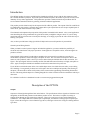
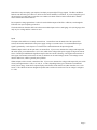
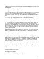
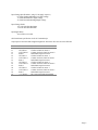
OPTO-26
User's Manual
Page 1
Introduction
The OPTO26 product is an opto-coupled interface intended specifically for use with the J201 connector on the
HS-1 and HS-20 Indexer products. It provides optical isolation of inputs to the Indexer to provide necessary noise
immunity for any control applications. This product also provides a transition from the 26 pin ribbon cable to
screw terminal connections which are generally preferred in industrial applications.
This product provides isolation only for the inputs to the HS-1/HS-20 product. The outputs of the HS-1 and HS-20
are unaffected by this product. Generally these outputs drive opto-coupled devices such as opto coupled inputs of
motor drives, opto based solid state relays (SSRs).
The schematic and component layout pictorial of this product is included in this manual. Also, several application
notes describing the wiring connections for typical devices that you might be using are shown. If you are using
components which you feel are not covered by the drawings, we are happy to provide our advice on the best way to
hook up your system.
Also, we have provided some wiring tips which will help lead to successful operation of your machine.
General System Wiring Practice
When you install a control system to support an industrial application, you must consider the possibility of
electrical noise interference with proper operation. Some signals are susceptible to noise, and some signals are
producers of noise.
Output signals which connect from the indexer module to the step motor driver module are generally low
electrical noise producers, and are not highly susceptible to noise. The wires from a motor power driver to the
motor are noise producers, and it is best if you can use dual twisted pair shielded cable for this connection. See
figure 3. The input signals which are normally used for limit and home sensor functions, are highly susceptible to
noise. Again, twisted pair shielded wire should be used for this connection to keep noise out.
If you decide to run both the motor driver wires and the input sensor wires inside the same cable, you are asking
for a challenge. It can generally be done, but it will require more strict technique and possibly some filtering of
the inputs. The motor drive cables switch polarity of the current each step producing an alternating field around
the wire. This along with the input wires running alongside for 10 feet can form an effective transformer which you
don't want.
For a shield to be effective it should not be used as a current carrying ground return path.
Description of the OPTO26
Outputs
Outputs are fed straight through from J201 on the Indexer. The specifications of these signals are listed here even
though they are defined and generated on the Indexer product its-self. The indexer is capable of sourcing or
sinking current through an opto-coupled type interface. There are several types of opto-coupled interfaces in
common use. For example IMS uses a sourced opto-coupled input, and API uses a sink type opto-coupled input.
Figure 1 shows the wiring for a sourced interface type driver, and Figure 2 shows the wiring for a sinking interface
type driver.
Page 2
Some drivers may not employ opto couplers, but simply accept straight TTL type signals. The HS-1 and HS-20
Indexers can drive this type of drive too, however some noise immunity is sacrificed. If you are using this type of
driver interface you must take even greater care to make sure that no electrical noise from the driver module
causes interference with the Indexer.
Do not permit a voltage greater than 5 volts to be used with the outputs of the HS-1 or HS-20, even through the
LED side of an opto-coupled type interface.
The leads which run from the OPTO-26 to the motor module inputs can be a small gauge wire (22-28 gauge) since
only very low voltage and low current are used.
Inputs
The inputs of the OPTO-26 is actually current driven. Current flows into the anode side of the Opto's LED
section, and out the cathode back to the power supply serving as a current source. It is assumed that the input
signal is generated by a switch open or a switch closure connected between the input and ground.
When this input switch is in the open state, no current flows. If you were to measure the voltage at the input with
the switch open, you would measure 4.5 to 5 volts, which is the voltage of the power supply serving as the current
source. But keep in mind that the significant aspect is that 'no current' is flowing. One negative characteristic of
some types of electronic switch in the off state, is that there can be some leakage current. This leakage current
must be under 2 ma, which is generally not a problem.
When an input switch is closed, current does flow. If you were to measure the voltage at the input with your switch
closed you might measure 0 volts, or .8 volts, or 1.2 volts, depending on the type of electronic or mechanical
switch you are using. Some device outputs employ an electronic circuit which even when closed has over 1 volt
across it. The OPTO-26 has been designed to permit such a switch to be used even if its 'on voltage' is as high as
1.5 volts.
Page 3
For the purposes of illustration the input switches are divided into 4 categories as listed below (See Figure 4 at the
end of this manual):
Type 1: Mechanical switch closure to ground
Type 2: Open collector switch to ground
Type 3: TTL totem pole outputs
Type 4: SPDT Mechanical Switch
Type 1: Mechanical switch closure to ground assures current flow (with characteristicvoltage of very near 0 volts)
and no current flow (a high input) when the switch is open. When the switch is in the closed position it is
relatively immune to noise, but when it is in the open position the input wire is left floating and is susceptible to
noise.
Type 2: Electronic open collector switch to ground includes any single transistor,darlington pair, or
phototransistor arrangement capable of sinking 3.5 mA of current at 1.5 Volts saturated or less. When this type of
switch is in the on state it may have a voltage of 0.4 to 0.8 volts, unless it is a darlington type in which case it may
have a saturation voltage of 1.1 to 1.5 volts. When this switch is on it is realtively immune to noise, but when it is
off it floats like type 1.
Type 3: TTL totem pole outputs are completely compatible sources of input, and behave like type 2 inputs. If any
TTL inputs are used in your system and if you use a 'user isolated power supply', ensure that the user isolated
power supply is 5 volts regulated. When this input type is in the low state it will have a voltage below .8 volts, and
when it is in the high state it will have a voltage of 2.4 to 5 volts. It is relatively immune to noise in both states,
however be sure that no voltage higher than 5 volts ever drives the line. Some opto interruptors are available in
'totem pole' output configuration.
Type4: To achieve a characteristic similar to type 3 when using an electro-mechanical switch, you can wire a
SPDT switch as shown. When the switch is in the low state it is identical to type 1, but when it is in the high state
the input is clamped to the +5 volts which makes this configuration relatively immune to noise in both states.
User Isolated Power Supply Provision
As shipped, the OPTO26 product uses resistor capacitor isolation of the HS-1 power supply, provided by R101 and
R202 and C101. The voltage available between pins 23 and pin 9 comes from the HS-1. Many applications may
not require full isolation from the HS-1 and HS-20 power supply. But if the user wishes to totally isolate the
inputs a separate power 'user isolated power supply' can be used. To gain total electrical isolation, there must be no
electrical connection between the external switches or proximity sensors, and the HS-1 or HS-20 controller
product. This implies that the external devices may not draw their power from, nor reference (connect to) the
indexer ground (pin 9) or the indexer +5 Volt supply (pin 23).
In order to achieve total electrical isolation from the indexer and its input signals, resistors R101 and R102 must
be removed from the OPTO26 board. An external power source must then be connected between pins 23 and 9 of
the OPTO26 terminal strip J2. This user supply may be between 5 volts and 12 volts providing the voltage does not
violate the voltage specifications of any other component attached to the system. Under certain circumstances a
voltage as high as 24 volts may be used, but this would require a version of the OPTO-26 with minor component
changes, which can be made available for an OEM application.
Electrical Specifications for OPTO26 Inputs
Input Current Sinking Specifications
3.5 mA Minimum to Guarantee Low Input
1.7 mA Maximum Sinking/Leakage Allowable for High Input Level
Page 4
Input Voltage Specifications ( using 5 Volt supply at pin 23 )
0.0 Volts Working Minimum Low Input Voltage
1.5 Volts Maximum Low Input Voltage
5.0 Volts Recommended High Input Voltage
Input Voltage Limits
+12 Volts Absolute Maximum
-12 Volts Absolute Minimum
Input Signal Delay
20 to 40 micro-seconds
OPTO26 Pinout Specification for J2/J3 Terminal Strips
Output pins are not listed and straight through from J201 of the HS-1 and J1 on the OPTO26.
Pin #
9
11
12
13
14
15
16
17
18
19
20
21
22
23
Name
Ground
CW Limit 0
CCW Limit 0
Index 0
CW Limit 1
CCW Limit 1
Index 1
CW Limit 2
CCW Limit 2
Index 2
CW Limit 3
CCW Limit 3
Index 3
+ 5 V Source
Function
HS-1 referenced with R101 installed
Clockwise limit for motor 0
Counter clockwise limit for motor 0
Index/Mark input for motor 0
Clockwise limit for motor 1
Counter clockwise limit for motor 1
Index/Mark input for motor 1
Clockwise limit for motor 2
Counter clockwise limit for motor 2
Index/Mark input for motor 2
Clockwise limit for motor 3
Counter clockwise limit for motor 3
Index/Mark input for motor 3
HS-1 sourced with R102 installed
Page 5