1
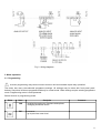
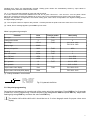
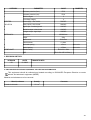
APLISENS
Manufacture of pressure transmitters
and control instruments
User’s manual
PMS-770T
TABLE OF CONTENTS
1. INTRODUCTION
1.1. General information
1.2. Features
1.3. Safety
1.4. EMC considerations
2. INSTALLATION
2.1. Unpacking
2.2. Mechanical assembly
2.3. Electrical connections
3. OPERATION
3.1. Programming
3.2. Set-point adjustment
3.3. Error codes
3.4. Display and outputs test
4. TECHNICAL SPECIFICATIONS
5. REVISION HISTORY
6. DISCARDED ELECTRONIC EQUIPMENT COLLECTING INFORMATION.
DESCRIPTION
SYMBOL
CAUTION or WARNING: Tells you about the risk of electrical shock.
CAUTION, WARNING or IMPORTANT: Tells you of circumstances or practices than can effect the instrument's
functionality and must refer to technical documentation.
INFORMATION: Helpful information.
INFORMATION: Discarded electronic equipment collecting
1
1. INTRODUCTION
1.1. General information
PMS770T is panel meter for a wide range of industrial applications. Provides measurement of voltage and
current process signals, analogue signal retransmission and ON/OFF relay control.
1.2. Features
Measurement - User programmable 4-digit read-out of voltage or current signals is provided. Filtering timeconstant, read-out rounding and decimal point position may be also programmed. The unit features also a 10
point linearisation routine.
Bargraph indication - 20 point, tricolour LED bargraph allows easy judgement of levels and threshold values.
Control outputs - 4 relay outputs are available. Threshold levels with individual hysteresis and ON/OFF
function are user programmed.
analogue output - The instrument has 4-20mA fully isolated output for analogue retransmission.
Sensor excitation - 24VDC/25mA isolated output provides sensor excitation.
1.3. Safety
Hazardous voltage exist within enclosure. Only trained personnel should perform installation and service.
Electrical wiring should be performed in accordance with all applicable national standards and
regulations. Instrument is protected in accordance with Class II of EN-61010-1.
- read the manual carefully before installation,
- disconnect power supply before installation and wiring,
- do not touch the terminals while power is being supplied,
- do not attempt to operate the instrument if any damage is found,
- do not operate the unit in aggressive or explosive environment,
- do not expose the instrument to condensing moisture,
- provide sufficient air circulation to keep the temperature in specified range.
1.4. Electromagnetic compatibility
Instrument meets EN-61326 EMC standard requirements for industrial environment.
Follow listed below instructions to provide proper operation in real conditions:
- Do not install the product near devices generating strong electromagnetic fields,
- wire the lines connected to the meter separately from power lines carrying high voltages or currents,
- use twisted or shielded signal lines in noisy environment,
- always apply functional grounding,
- apply external surge protectors close to the unit if long lines are connected,
- apply additional filtering in noisy environment.
2
2. INSTALLATION
2.1. Unpacking
The shipping carton should contain:
PMS770T meter
fixing clip
operating manual
1 pcs,
2 pcs,
1 pcs.
Unpack the instrument and check it for obvious signs of damage. If any damage occur notify the supplier and
do not attempt further use. If the unit appears to be in good condition read the Operating Manual before
installation and use.
Fig.1 PMS770T basic dimensions.
2.2. Mechanical assembly
The unit is designed for front panel mounting. It requires panel cut-out according to the specification with
proper distance to other devices.
Mounting procedure:
- put the meter from the front side into the panel cut-out,
- assmble fixing clipses (plastic screws should be placed inside the both fixigs),
- attach fixing clipses by putting in housing holes and sliding backwards,
- tighten the screws just enough to hold the housing firmly in place.
3
2.3. Electrical connections
Disconnect power supply before installation and wiring. Check power supply voltage on instrument's
label.
Electrical connection procedure:
- check if the unit is properly fixed,
- unplug terminal blocks on the rear wall,
- make required connections according to wiring table and diagrams,
- replug terminal blocks,
- check the connections before applying power INCORRECT CONNECTIONS CAN DAMAGE YOUR METER!
Connector
Pin number
Symbol
Terminal description
Rating
POWER SUPPLY
RELAY OUTPUT
ANALOGUE OUTPUT
ANALOGUE INPUT
AUX. SUPPLY
1
N
supply
2
L
supply
3
NO1
4
C1
5
NO2
6
C2
7
NO3
8
C3
9
NO4
10
C4
11
Out 4-20mA
analogue output
12
Out 4-20mA
signal ground
13
In: +V
analogue voltage input
10V
14
In: +mA
analogue current input
20mA
15
In: 0V
analogue input common
16
24VDC: -
aux supply negative
17
24VDC: +
aux supply positive
AL1 relay NO
AC 90-260V 50/60Hz
1A/250VAC
AL1 relay common
AL2 relay NO
AL2 relay common
AL3 relay NO
AL3 relay common
AL4 relay NO
AL4 relay common
4-20mA
24VDC
4
Fig. 2 Wiring diagrams.
3. Meter operation.
3.1. Programming
Incorrect programming may cause incorrect read-out and uncontrolled output relay operation!
The meter has many user-selected programme settings. All settings may be done with front panel pushbuttons. Set-points levels are programmed directly in normal mode. Other settings require entering programme
mode. Programming menu is code protected.
Button function in programming mode.
Button
Name
Description
CHG
- scrolling through menu functions and options
- changing numerical values
ESC
- ESCAPE
- go to previous menu level
Comments
5
Button
Name
ENT
Description
Comments
- ENTER, access to function
- selected value/option confirmation
To enter programming mode press ESC key for 2 seconds until „P.cod” message appear. Then press
ESC, CHG,CHG, ENT combination. „Fn00” message should appear.
In programming menu several functions are available. Detailed function description is given in the table.
Use CHG key to navigate through the functions and ENT key to enter selected function. Numerical values
should be set digit by digit. Flashing digit should be adjusted using CHG key and stored with ENT key.
All the settings are stored in non-volatile memory while leaving the programming menu if ENT key is pressed
while “SAVE” message appears. If ESC key is pressed, changes are not stored and the meter returns to
normal mode.
Programming menu.
Menu
Description
function
Available options
Default setting
Fn00
input
selection
I- 0-20mA current input active,
U- 0-10V voltage input active
I
Fn01
linearization
points
2 – 10
2
Fn02
display
scaling
P01 - Pnn
scaling points
-9.99 - 99.99
input value (with DP)
-999 - 9999
display value
decimal point 0000; 0.000; 00.00; 000.0
Fn04
display
rounding
1, 2, 5, 10
1
Fn05
filter timeconstant
0 – 0, 1 - 20ms, 2 - 40ms, 3 - 80ms, 4 160ms, 5 - 320ms, 6 - 640s, 7 - 1.28s, 8 2.56s, 9 - 5.12s
2
Fn06
bargraph
mode
3C – three colour (green, yellow, red)
1C - single colour (green)
3C
Fn07
set-point
mode
AL1, AL2, AL3, AL4
L - low
1 – 9999 hysteresis= [display divisions x2]
Fn08
output scaling P01 - zero (low)
P02 - full scale
-999 - 9999 meter's display value
2 - linear scale
P01 : 00.00 : 0000 Define input value and display
P02 : 20.00 : 2000 value for each scaling point (1)
Fn03
H - high
Comments
00.00
AL1 : H : 1
AL2 : L : 1
AL3 : H : 1
AL4 : L : 1
Leading zeros are suppressed
1 - without rounding
(2)
Individual H/L and hysteresis
setting for each set-point
(3)
P01 : 0000 : 4.00 Define meter's display value
P02 : 2000 : 20.00 and output current for both
scaling points.
03.00 - 21.00 [mA] output current
Fn09
all reset
Ecod (4)
Reset to default setting
Remarks:
(1) - The meter is factory set to linear scale with two scaling points. If non-linear scale is needed the required number of
scale points should be set in Fn01 function at first. Then, the input and display values for each point should be set.
6
Doubled input values are automatically rejected. Scaling point values are automatically sorted by input values in
ascending order, after each Fn02 function access.
(2) - In 1 colour mode the bargraph is green with red set-points.
In 3 colour mode the central zone between AL3 and AL4 is green. Zones AL1 - AL3 and AL2 - AL4 are yellow. Zones
above AL1 and below AL2 are red. Relation AL2<=AL4<=AL3<=AL1 should be true for proper colour zone display.
Bargraph 0% indication corresponds to the lowest scaling point, while 100% corresponds to the highest scaling point of
the digital display analogue.
(3) - The set-point number is equal to relay number. Overall hysteresis is equal to twice the value set in Fn07 function.
(4) - While „Ecod” message appears, press ENT key four times.
Meter's programming example
Parameter
Value
Function number
Menu setting
current
Fn00
I
2
Fn01
2
input range
4-20mA
Fn02
display range
0-3000
P01 : 04.00 : 0000
P02 : 20.00 : 3000
decimal point position
000.0
Fn03
000.0
rounding
none
Fn04
1
filter time constant
240ms
Fn05
3
AL1 „ON” level
>2500
(1)
AL1 : 2500
AL2 „ON” level
<1000
(1)
AL2 : 1000
AL1 hysteresis
10
Fn07
AL1 : H : 0005
AL2 hysteresis
20
input type
scaling points number
output current at zero display
5mA
output current at full scale (3000) display
19mA
AL2 : L : 0010
Fn08
P01 : 0000 : 05.00
P02 : 3000 : 19.00
(1) - settings available in normal mode
AL1+h
AL1
AL1-h
AL1=2500 - set-point value
AL1+h=2505 - turn-on level
AL1-h=2495 - turn-off level
h=5 - programmed value
H=2xh - overall hysteresis
Fig.3 Hysteresis definition.
3.2. Set-point programming
Set-points are programmed in normal mode of the meter using front panel keys. Press CHG key for 3 seconds
to enter AL1 to AL4 programming. Choose set-point to be changed with CHG and press ENT key. Adjust each
flashing digit using CHG key and store the value with ENT key.
The relation AL2<=AL4<=AL3<=AL1 should be true in 3 colour bargraph mode for proper colour zone
display.
7
3.3. Error codes
Error code
Description
Possible reasons
ErrF
calibration memory error
InIF
calibration memory
initialization
ErrU
user memory error
InIU
user memory initialization
If the message appears after each
power-up contact the service.
input under/overrange
-check signal source
check input circuitry
display
flashing
-abnormal EMC condition
-internal fault
Operation
Turn off the meter for 5 s. If message
reappears after power-up, contact the
service.
Turn off the meter for 5 s. If message
reappears after power-up, contact the
service.
-abnormal EMC condition
-internal fault
Turn off the meter for 5 s. If message
reappears after power-up press ENT
button. Meter reads factory settings with
momentarily displayed InIU message.
-
9999
display overrange
(flashing)
-incorrect meter settings
-check signal source
-incorrect input connection check meter's scaling
-internal fault
input circuitry
-check
-999
display underrange
(flashing)
-incorrect meter settings
-check signal source
-incorrect input connection check meter's scaling
-internal fault
input circuitry
-check
3.4. Display and outputs test.
PMS770T has special test procedure for LED display, relays and version check. The test is initiated when the
meter is powered-up with CHG key pressed. LED segments are lighted-up in following cycle:
- four digit firmware version code,
- digital display (all segments simultaneously),
- alarm leds with output relays activation,
- bargraph green (all segments simultaneously),
- bargraph red (all segments simultaneously),
- all LED segments simultaneously.
The ENT key toggles between simultaneous and single segment activation during test. ESC key closes the
test.
8
4. TECHNICAL SPECIFICATION
CATEGORY
INPUT
PARAMETER
Accuracy
Temperature coefficient
CURRENT INPUT
VOLTAGE INPUT
VALUE
+/-0.25% FS
+/- 100ppm / oC
Internal resolution
12 bit
Effective sampling rate
100Hz
Display update rate
5Hz
Filter time constant
0-5,12s
Normal Mode Rejection Ratio (NMRR)
>=66dB
f=50-500Hz;
U,I(peak)<=120% FS
Range
0-20mA
-0.1 .. +20.5mA
Input resistance
<65ohm
Input protection
internal PTC, 50mA
Range
Input resistance
Voltage overrange
CONTROL RELAY
Rating
OUTPUT
Contact configuration
Open contact withstand voltage
Contact life mechanical / electrical
0...10V
1A / 250VAC
4 x NO
1000VAC
15x106 / 1x10⁶
ANALOGUE OUTPUT
Range
4-20mA
(PASSIVE)
Output voltage range
10-30VDC
Accuracy
+/- 0.1% FS
Resolution
12 bit
Output voltage effect
Refresh rate
30Hz
SENSOR
Voltage
EXCITATION
Current max
25mA
Current limit
continuous
Power consumption
DISPLAY
Digits
Digit hight
Bargraph resolution
ENVIRONMENTAL
Operating temperature
Storage temperature
Humidity (relative)
3.8-21mA
+/-20ppm / V
36V
Voltage
resistive load
+/- 100ppm / oC
Overvoltage protection level
Overvoltage protection level
-0.05 ... +10.5V
300%
250VA
Temperature coefficient
|U|<=30V
>=1Mohm
Load capacity
POWER SUPPLY
COMMENTS
transil
24VDC, +/-10%
36V
90-260VAC 50/60Hz
<4W
4
Green LED
9mm
20
5..40oC
-10 .. +70oC
10-95%
without condensing
9
CATEGORY
PARAMETER
VALUE
Enclosure protection (front)
IP-54
Enclosure protection (rear)
IP-20
Pollution degree
2
Overvoltage category
II
ELECTRIC
Power supply - other circuits
2300VAC
ISOLATION
Relay outputs - other circuits
2300VAC
Signal input - functional ground
1000VAC
Excitation output - other circuits
1000VAC
analogue output - signal input
1000VAC
MECHANICAL
Dimensions
48x96x96mm
Weight
230g
Panel cut-out
COMPLIANCE
COMMENTS
45x91.8mm
Panel thickness
0..10mm
Horizontal spacing
>60mm
axis to axis
Vertical spacing
>150mm
axis to axis
Electrical safety
EN 61010-1:2004
EMC
EN 61326:1997/A3:2004(U)
5. REVISION HISTORY
VERSION
DATE
1.01
01.2008
CHANGES INFO
6. DISCARDED ELECTRONIC EQUIPMENT COLLECTING INFORMATION.
This equipment should be collected and treated according to 2002/96/EC European Directive on waste
electric and electronic equipment (WEEE).
Material and substances to be removed:
Material, substance
Printed circuit boards
Quantity
131
Comments
cm2
10