1
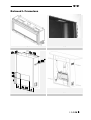
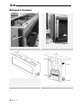
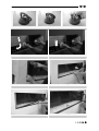
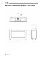
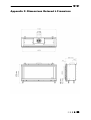
Relaxed L 40010636 - 0736 UK Installation guide IRL UK IRL General 1-1 (Wood set) 1-2 (Twigset) 1-3 (Pebbles) 1-4 1<<<< 1-5 UK IRL Relaxed L Frameless 2-1 2-2 2-3 2-4 >>>>2 UK IRL Relaxed L Framed B A 3<<<< 3-1 3-2 3-3 3-4 UK IRL 4-1 1 3 2 4-2 4-3 4-4 4-5 4-6 4-7 >>>>4 UK IRL Inleiding 1 Content............................................................................................... 6 2 Safety and general information .................................................................. 7 3 Installation requirements ......................................................................... 8 4 5 3.1 Builders opening.............................................................................. 8 3.2 Flue requirements............................................................................ 9 Instruction for Installation ....................................................................... 11 4.1 Gas connection .............................................................................. 11 4.2 Preparing the appliance.................................................................... 11 4.3 Place the appliance......................................................................... 11 4.4 False chimney Brest ........................................................................ 11 4.5 Building the False Chimney Brest with a Frameless situation........................ 11 4.6 Building the False Chimney Brest with a Frame........................................ 12 4.7 Placing the Pebbles or placing the Log/Twig set ...................................... 12 4.8 Placing the glass............................................................................. 12 4.9 Flue requirements........................................................................... 13 Commissioning (functional checks) ............................................................. 14 5.1 Pilot ignition check ......................................................................... 14 5.2 Check functional burner and pilot burner............................................... 14 6 Handing over (final check and customer briefing) ........................................... 15 7 Servicing ............................................................................................ 15 7.1 Routine anual servicing .................................................................... 15 7.2 Cleaning the glass ........................................................................... 15 7.3 Cleaning the combustion chamber and burner ......................................... 16 7.4 Rebuild to other gas category (e.g. Propane/butane) ............................... 16 Appendix A: Example calculation..................................................................... 17 Appendix B: Flue restrictor............................................................................ 18 Appendix C: Installation of the flue.................................................................. 19 Appendix D: Technical specifications ................................................................ 20 Appendix E: Dimensions Relaxed L with Frame .................................................... 21 Appendix F: Dimensions Relaxed L Frameless ...................................................... 22 Appendix G : Dimensions Ventilation grid........................................................... 23 Appendix H : Dimensions Service Hatch ............................................................. 24 5<<<< UK IRL 1 Content Note: these instructions should be read carefully and retained for future reference. Please leave these instructions with the user. This guide is concerning the following types of appliances: • RELAXED L with frame • RELAXED L frameless Special features: • Room sealed appliance, inlet and outlet are led to the outside using a natural draught concentric pipe system (100 mm/150 mm) (no power fan required) • Air supply and flue-gases go to outside atmosphere through wall or roof • Remote Control standard • Faber false chimney breast optional • Meets the requirements of the European Gas Appliance Directive (GAD) and carries the CE mark >>>>6 UK IRL 2 Safety and general information Before installation, ensure that the local distribution conditions (identification of the type of gas and pressure) and the adjustment of the appliance are compatible. This gas appliance is factory set and can not be adjusted. This appliance does not contain any component manufactured from asbestos or any asbestos related products. Ventilation This appliance is room-sealed and doesn't require purpose provided ventilation. Never use the appliance if it has a broken glass. General safety It is the law in the UK that all gas appliances, are installed by a competent person in accordance with the Gas Safety (Installation and Use) Regulations (as amended), the relevant British Standards for Installation work, Building Regulations, Codes of Practice and the manufacturers instructions. Always use an additional guard if there are elderly, infirm or children in the same room of the appliance. The installation should also be carried out in accordance with the following where relevant: • BS5871 Part1 • BS5440 Parts 1 & 2 • BS1251 • Building Regulations Document J (as applicable) • Building Regulations and Standards issued as relevant by the Department of the Environment or the Scottish Development Department • In the Republic of Ireland installation should be carried out in accordance with IS813, ICP3, IS327, Building Regulations, Codes of Practice, the manufacturers instructions and all other regulations in force Failure to comply with the above could leave the installer liable to prosecution and invalidate the appliance warranty. 7<<<< UK 3 IRL Installation requirements Note: Since the appliance is a source of heat, circulation of air occurs. Therefore it is of importance that you do not use the appliance shortly after a renovation of the home. Because of the natural circulation of air, moist and volatile components from paint, building materials, carpet etc. will be attracted. These components can settle onto cold surfaces in the form of soot. As on all heat producing appliances, soft furnishings such as blown vinyl wallpaper placed too near to the appliance may become scorched or discoloured. This should be born in mind when installing the appliance. 3.1 Builders opening The Relaxed L can be build in a non-combustible fire place or builders opening. This could be either an existing builders opening or a new made prefab builders opening. When you apply your own false chimney breast design to the Relaxed L you have to meet these general requirements: • The false chimney breast has to be made of inflammable material • Always install the appliance before building up the false chimney breast • Check figure 2-3 for the dimensions • Always ventilate the space above the appliance using vents to assure a good aircirculation • The plaster of the outside has to be resistant to a high temperature. Therefore use the plaster materials especially made for this, to prevent discolouring (min. 100 °C temperature resistant) • Make sure the plaster dries well before using the appliance. Let the thickness in mm be the number of days the plaster has to dry 3.1.1 False chimney breast Relaxed L frameless • Use the steel building guide (fig. 2-1) mounted on the front of the appliance • Make a framework of metal studs around the steel building guide; keep in mind the thickness of the Promatec you use! • Place metal studs at every corner of the false chimney brest; keep in mind the thickness of the Promatec you use! • Build with Promatec around the steel building guide (fig.2-2) • Build the rest of the false chimney brest • Use 12 mm Promatec for the front of the false chimney breast. >>>>8 UK IRL 3.1.2 False chimney brest RELAXED L with frame • Make a framework of metal studs around building guides A and B (fig. 3-1); keep in mind the thickness of the Promatec you use! • Place metal studs at every corner of the false chimney brest; keep in mind the thickness of the Promatec you use! • Build with Promatec around the appliance against the building guides A and B (fig.3-1); keep in mind that the appliance has to stick out of the walll and therefore nothing must be build before the building guides! • Build the rest of the false chimney brest 3.2 Flue requirements • The appliance is of the type C11/C31. The appliance will need to be supplied with the approved flue pipes and terminal, it is not possible to supply your own • a horizontal extension with elbows is allowed for a maximum of 5 meters (depending on the situation) • Minimal 1 meter vertical and maximal 12 meters vertical (depending on situation) Determine on the base of the example calculations in Appendix A and on the base of the table in Appendix B if the desired situation is possible. To establish this you will need to calculate: • The effective height (this is the real difference in height between the upper side of the appliance and the terminal) • The total horizontal extension. This is the total horizontal flue length where: 1. each 90-degree bend, which is in the horizontal area, counts for 2 meter 2. each 45-degree bend, which is in the horizontal area, counts for 1 meter 3. elbows and bends at the transition of horizontal to vertically are not to be counted 4. the wall mounted terminal or roof terminal counts for 1 meter 3.2.1 Terminal position Verify if the required terminal position meets the local installation regulations regarding disturbance, good functioning and ventilation (see also appendix G). Note: • The terminal must be located so that the outlet is not obstructed. If the flue terminal is located within 2 meters of a footway path or where people could come into contact with it, then a suitable terminal guard must be fitted 9<<<< UK • IRL Terminals located close to shared walkways, footpaths etc. could be subject to legal constraints and this should be pointed out to the customer before installation. If in any doubt about flue location advice should be sought from local building control, or if appliance-related, from the manufacturer including wherever possible a dimensioned sketch • Avoid locating the terminal in close proximity to plastic materials such as gutters or other combustibles. If this is unavoidable then a suitable deflector should be made. • Some important requirements for a good functioning are • The wall-mounted terminal has to be at least 0,5 m off o Corners of the building o Below eaves o Balcony's etc. unless the duct is dragged to the front side of the overhanging part o The roof mounted terminal has to be at a distance of at least 0.5 meters of the sides of the roof, excluded the ridge 3.2.2 Using an existing chimney as air inlet You can connect the appliance onto an existing chimney. The existing chimney then functions as air supply, where a flexible stainless steel liner (to BS715) of 100 mm performs the flue function. Requirements: • Any existing chimney used as an air supply must only service this a0ppliance. • A chimney that has previously been used for solid fuel must be swept before use. • The existing chimney needs to be airtight. • The existing chimney needs to have an opening of min. 150 x 150 mm. • The chimney needs to be intact and well looked after. • Use the adjustable roof-mounted-terminal especially made for this, and the chimney connection set. > > > > 10 UK IRL 4 Instruction for Installation 4.1 Gas connection Installation pipes should be in accordance with BS 6891. Pipe work from the meter to the appliance must be of adequate size. The complete installation including the meter must be tested for soundness and purged as described in the above code. A means of isolation must be provide in the supply to facilitate servicing. The connection should be made in 8 mm copper or similar semi flexible tube. (max 1 meter). Ensure that the gas pipe does not interfere with the removal or replacement of the burner tray or of the controls. The gas connection is nut and olive suitable for 8 mm pipe. 4.2 Preparing the appliance • Remove the packaging and pallet under the appliance • Don’t forget to remove the separate packed parts out of the top of the appliance • Pre-adjust the appliances’ height by adjusting the couple legs 4.3 Place the appliance • Check paragraph 3.1 before commencing installation • If possible, first place the appliance before assembling the flue • Check if the floor and wall are sufficiently level and perpendicular. Fix if not • Prepare the gas-connection; normally the gas control block is positioned at the right side but these can be positioned anywhere within 1,2 m of the centre of the appliance • adjust the appliances’ height • Make sure the appliance is level 4.4 False chimney Brest Note: Always place ventilation grids in the False chimney Brest 4.5 Building the False Chimney Brest with a Frameless situation • Use the steel building guide (fig. 2-1) mounted on the front of the appliance • Make a framework of metal studs around the steel building guide; keep in mind the thickness of the Promatec you use! 11 < < < < UK • IRL Place metal studs at every corner of the false chimney brest; keep in mind the thickness of the Promatec you use! • Build with Promatec around the steel building guide (fig.2-2) • Build the rest of the false chimney brest 4.6 • Building the False Chimney Brest with a Frame Make a framework of metal studs around building guides A and B (fig. 3-1); keep in mind the thickness of the Promatec you use! • Place metal studs at every corner of the false chimney brest; keep in mind the thickness of the Promatec you use! • Build with Promatec around the appliance against the building guides A and B (fig.3-1); keep in mind that the appliance has to stick out of the walll and therefore nothing must be build before the building guides! • Build the rest of the false chimney brest 4.7 Placing the Pebbles or placing the Log/Twig set • Place the pebbles (fig 1-3) or in case of a Log/Twig set spread the bottom of the appliance over with the decorative black/yellow materials • Place the Twig set according to figure 1-1 or place the Log set according to fig.1-2 Never spread over more than one layer pebbles or embers! Always check if the pilot light can be seen! 4.8 Placing the glass Two suction pads are delivered with the appliance to make placing/removal easier. Always clean the suction lifters before use Place the suction lifters on the glass and bring the handles towards each other (see figure 4-1) Slide the top of the glass carefully in the glass opening and simultaneously slide the glass upwards Turn the bottom of the glass backwards Slide the glass downwards till it stops Place the strips at each side (see figures 4-3 and 4-4) Place the seal cord around the glass opening and check for soundness Place the decorative bottom strip Place the decorative side strips over de magnets (if applicable) Place the Frame Remove stains from the glass (they can’t be removed after the fire has been lit) > > > > 12 UK IRL 4.9 Flue requirements The appliance is of the type C11/C31. The appliance will need to be supplied with the approved flue pipes and terminal, it is not possible to supply your own. The minimum effective height of the flue system must be 1 meter! 4.9.1 Flue routing - The terminal locations, through the wall as well as through the roof - A horizontal extension with elbows is allowed for a maximum of 5 meters (depending on the type and situation) - Vertical max. 12 meters. (depending on the type and situation) Determine on the base of Appendix A and B depending on the type and terminal position, if the desired situation is possible. To establish this you will need to calculate: - The effective height (this is the real difference in height between the upper side of the appliance and the terminal); - The total horizontal extension. This is the total horizontal flue length where: o Each elbow, which is in the horizontal area, counts for 2 meters; o Each 45-degree bend, which is in the horizontal area, counts for 1 meter; o Elbows and bends at the transition of horizontal to vertically are not to be counted; o The wall mounted terminal counts for 1 meter. 4.9.2 Flue restrictor If applicable, in the table is also stated the size of a flue restrictor. This restrictor needs to be fitted in the combustion chamber when placing the appliance (see chapter 4.2). Normally the smallest flue restrictor is fitted. 13 < < < < UK IRL 5 Commissioning (functional checks) 5.1 Pilot ignition check • Ignite the pilot light as described in the user manual • Check if the pilot burner stays alight • Extinguish the pilot burner 5.2 Check functional burner and pilot burner The appliance is preset to give the correct heat input. No further adjustment is necessary. Always check the inlet pressure and burner pressure: • Turn off the gas valve on the appliance • Turn the inlet pressure test point C and apply the manometer • Check if the measured pressure is the same as the prescribed pressure • Perform this measuring when the appliance burns on full capacity and when only the pilot ignition burns • When the pressure is too low, check if the gas pipes are made of material with the right diameter • When the pressure is too high (more than 5 mBar overpressure) you may not install the appliance and you should contact your gas company • Always check the burner pressure when the functional pressure is right • Open the burner pressure test point D • The pressure should match the described pressure. If this is not the case, then contact the supplier Note: After checking the burner pressure, the inlet pressure test point has to be shut and checked for gas-tightness. A B C A. Governor B. Inlet pressure testpoint C. Burner pressure testpoint > > > > 14 UK IRL 6 Handing over (final check and customer briefing) • Instruct the customer on the full operation of the appliance and the remote control, including replacement of batteries • Advise the customer how to clean the appliance including the glass • Hand over these instructions including the user guide to the consumer • Recommend that the appliance should be serviced by a competent person at least once a year 7 Servicing To ensure safe, efficient operation of the appliance, it is necessary to carry out routine servicing at regular intervals. It is recommended, that the fire is inspected/serviced by a competent person at least once a year. Important: Turn off the gas supply before commencing any servicing. Always test for gas soundness after refitting the appliance! 7.1 • Routine anual servicing Clean (if necessary): a. the pilot system b. the burner c. the combustion chamber d. the glass • Check the log lay and replace the embers (if applicable) • Do the functional test as described in chapter 6 • Check the flue system and terminal on damage and soundness (visual inspection) 7.2 Cleaning the glass Depending on the intensity of use, you can get a deposit on the glass. Remove the glass (see chapter 4.6). Remove the deposit with a special ceramic glass cleaner (ceramic cook-top cleaner) as follows: • Remove the front and the back. • Clean the glass. Handle the glass with clean hands, wear gloves if possible. • To fit the glass, proceed in reverse order. Make sure that the log set has been installed correctly before fixing the glass. 15 < < < < UK IRL Attention: Before placing the glass: check the glass sealing rope is in good condition and makes an effective seal. Be sure that there are no fingerprints on the glass. It is not possible to remove those prints after you burn the appliance for a while (they are burnt in). Place the glass in front of the appliance and fix the glass frame or use the glass clamps. 7.3 Cleaning the combustion chamber and burner If the burner is visibly damaged, this can affect the distribution of the flame, if so then replace the burner. Burner tray assembly Remove the front, glass, and log holder (if applicable) Break the gas supply at the control valve. Unscrew the burner assembly and take them out of the combustion chamber. 7.4 Rebuild to other gas category (e.g. Propane/butane) Rebuilding to another gas category is only possible by exchanging the complete burner plate. Ask your local dealer and bring the PIN (Product Identification Number) of the appliance. > > > > 16 UK IRL Appendix A: Example calculation Example calculation 1: Calculating horizontal extension fig. 2a: Flue length C + E = 1m + 1m 2m Elbows D = 2m 2m Total horizontal extension 4m Measure or calculate effective height (Hvert) Flue length A 1m Roof mounted terminal 1m Total effective height 2m Ex.1 Example calculation 2: Calculation horizontal extension fig. 2b: Flue length J + L = 0,5 + 0,5 1m Elbows K + M = 2m + 2m 4m Terminal 1m Total horizontal extension 6m Calculation effective height (Hvert) Flue length H 1m Looking up in the table in Appendix B shows that this situation is not allowed Ex .2 Always check if the calculated situation is allowed (see Apppendix B: Flue restrictor) 17 < < < < UK IRL Appendix B: Flue restrictor Determining of the right flue restrictor: • Calculate the total horizontal- and vertical length of the flue, according to the calculations displayed above • Determine according to the table the right flue restrictor size • When meeting an X, and when the values are outside the table, the combination is not allowed Normally the 30 mm flue restrictor is preinstalled Relaxed L Total effective height (m) • Horizontal length (m) 0 1 2 3 4 5 6 0 x x x x x x x 0.5 x x x x x x x 1 0 0 0 x x x X 1.5 30 30 0 0 x x X 2 30 30 30 0 0 0 0 3 40 30 30 30 0 0 0 4 40 40 30 30 30 0 0 5 50 40 40 30 30 30 0 6 50 50 40 40 30 30 0 7 50 50 50 40 40 40 x 8 60 50 50 40 40 x x 9 60 60 50 50 x x x 10 65 60 60 x x x x 11 65 65 x x x x x 12 65 x x x x x x > > > > 18 UK IRL Appendix C: Installation of the flue Connection with use of concentric duct material Make a hole of ø 153 mm for the wall or roof mounted terminal. The horizontal pipes need to rise away from the appliance at a rate of 3 degrees per metre Build the system starting from the appliance on. Make sure you place the pipes in the right direction, the narrow end towards the appliance. Make sure the pipes are fixed sufficiently, a wall clamp every 2m, so the weight of the pipes is not resting onto the appliance. The outside of the pipe can become hot (140 degrees). Stay 50 mm away from wall surface or sealing. Make sure to provide sufficiently heat resistant isolation when going through the wall or roof. Because of expansion or cooling down the concentric pipes can turn loose. It is recommended to fix the spring clip with a self tapping screw at inaccessible places. To get the exact measure flue length you can use cut down concentric pipe, wall mounted terminal or roof mounted terminal. To obtain a smoke sealed connection, the inner pipe must be 20 mm longer then the outside pipe. Connection onto an existing chimney For connection onto an existing chimney see the installation guide delivered with the chimney connection set 19 < < < < UK IRL Appendix D: Technical specifications Country Cat Appliance type Reference gas Input (nett) Efficiency class NOx-rate Inlet pressure Gasrate (Bij 15º C en 1013 mbar) Working pressure (high) Working pressure (low) Injector number Reduced input restraint Pilot assembly Injector code Flue System Flue size Std. Flue restrictor Gas control Connection kW mbar l/h gram/h mbar mbar mm mm mm GV 36 nut/olive UK II 2H3+ C11 of C31 G20 8 2 5 20 848 10 2.6 Bray 800 1.8 SIT 145-19 Nr.36 UK II 2H3+ C11 of C31 G31 8 2 5 37 315 IRL II 2H3+ C11 of C31 G31 8 2 5 37 315 28.6 7.2 Bray 260 1.1 SIT 145-19 Nr.23 IRL II 2H3+ C11 of C31 G20 8 2 5 20 848 10 2.6 Bray 800 1.8 SIT 145-19 Nr.36 Ø100-150 30 Ø100-150 30 Ø100-150 30 Ø100-150 30 8 mm 8 mm 8 mm 8 mm 28.6 7.2 Bray 260 1.1 SIT 145-19 Nr.23 > > > > 20 UK IRL Appendix E: Dimensions Relaxed L with Frame 21 < < < < UK IRL Appendix F: Dimensions Relaxed L Frameless > > > > 22 UK IRL Appendix G : Dimensions Ventilation grid 23 < < < < UK IRL Appendix H : Dimensions Service Hatch > > > > 24 UK IRL 25 < < < < UK IRL > > > > 26 www.faber.nl - [email protected] Saturnus 8 NL - 8448 CC Heerenveen Postbus 219 NL - 8440 AE Heerenveen T. +31(0)513 656500 F. +31(0)513 656501 40010636 − 0736