1
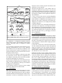
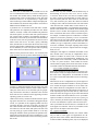
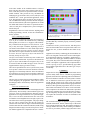
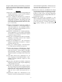
In “Proceedings of the 1993 AIAA Conference on Space Programs and Technologies,” Sept. 21-23, 1993, Huntsville, Alabama.
A HUMAN-MACHINE INTERFACE FOR RECONFIGURABLE SENSOR-BASED
CONTROL SYSTEMS
Matthew W. Gertz, David B. Stewart, and Pradeep K. Khosla
Dept. of Electrical and Computer Engineering
The Robotics Institute at Carnegie Mellon University
Pittsburgh, Pennsylvania 15213
Abstract
when the manipulator is operating aboard a shuttle or space
station, where the primary users may not necessarily be
specialists in the field of robotics.
The development of software for dynamically reconfigurable sensor-based control systems is a complicated and
tedious process, requiring specialization in real-time systems programming and an amount of time which may not
be available, for instance, in a space laboratory. The total
development time can be reduced by automatically integrating reusable software modules to create applications.
The integration of these modules can be further simplified
by the use of a high-level programming interface which can
integrate modules developed at different sites. We have developed Onika, an iconically programmed human-machine
interface, to interact with a reconfigurable software framework to create reusable code. Onika presents appropriate
work environments for both application engineers and endusers. For engineers, icons representing real-time software
modules can be combined to form real-time jobs. For the
end-user, icons representing these jobs are assembled by
the user into applications. Onika verifies that all jobs and
applications are syntactically correct, non-ambiguous, and
complete. They can then be executed from within Onika, or
can be saved as a stand-alone program which can be executed independently on the underlying real-time operating
system. Onika can retrieve and use software modules created at other sites with modules created locally. While Onika has been fully integrated with the Chimera real-time
operating system in order to control several different robotic systems in the Advanced Manipulators Laboratory at
Carnegie Mellon University, it can also function independently of Chimera. Onika will be used in connection with
NASA Langley Research Center’s Intravehicular Autonomous Robot (IVAR) space manipulator laboratory.
Much of the expense and tedium of software development
is caused by the limitations of textual code. To use a textual
language properly, the programmer must undergo expensive training. The deciphering, debugging, and use of realtime textual code is particularly time-consuming, especially when the code is cryptic, non-portable, and uncommented. In the past, researchers have created visual
programming languages (VPLs) to address the problems of
textual coding.1,2,3,4,5,6,7 However, these interfaces have
been, in general, either very high-level and narrow in
scope, or low-level and cryptic. Furthermore, these interfaces have not been designed with the specific requirements of real-time programming in mind. These
requirements include the need to switch from one job to the
next with minimal time loss, the need to modify the code of
a job while it is executing, and the need to coordinate many
jobs running in parallel.
In this paper, we discuss the development of a multilevel/
iconically-programmed human-machine interface called
Onika, and the software programming framework in which
it resides. Our primary motivations for designing such a
software framework include the following:
• Reconfigurable hardware, such as open-architecture
computer environments (e.g. VMEbus) and
reconfigurable machinery (e.g. RMMS14), require
reconfigurable software in order to take full advantage of all the capabilities of the hardware.
• Reconfigurable software is useful for supporting
multiple applications on a fixed hardware setup.
1. Introduction
• Generic graphical user interfaces and programming
environments for robotics and automation applications require that the underlying control system
be reconfigurable.9
The development of real-time software for sensor-based
systems is an expensive process, accounting for a significant portion of total application costs. This expense can be
reduced by automating the software development procedure. To do this, a user-friendly high-level programming
environment designed for the creation of reusable real-time
software is required. A programming interface of this type
would not only allow for the rapid development of software, but would also considerably ease the process of debugging real-time code. This would be especially useful
Other major advantages to designing applications to reuse
reconfigurable software, even for systems which do not
have to be reconfigurable, include the following:
• Reusable software: Any software that is developed
for a reconfigurable system is inherently reusable.
It is therefore not necessary to redevelop every
part of the system when designing a new application. Consequently, the development time for applications is significantly reduced.
Copyright ©1993 by the American Institute of Aeronautics and
Astronautics, Inc. All rights reserved.
1
have also been created for naïve users1,2,3,4,7; however, the
scope of any given interface of this type is generally narrow. The addition or major modification of routines controllable by the interface is beyond the abilities of its
typical user.
• Expandability: Existing hardware can be upgraded,
or new hardware or software added to the system,
with reprogramming the application.
• Technology transfer: A module (and hence the technology implemented within that module) can easily be transferred to another institution which is
also using the reconfigurable software framework. Technology transfer is thus very straightforward, even if different institutions are working
on very different applications or have very different system setups.
Traditional flowchart methods are often used in both
higher- and lower-level VPLs. Flow charts reduce the complexity of textual code somewhat, but can still be quite
cryptic and do not efficiently use screen space. Occasionally, pictures accompany or are used in place of the text (as
in Pict6 or HI-VISUAL4) within a flowchart, but this does
not help to give syntactic clues for programming. NassiSchneiderman flowcharts, used primarily for lower-level
programming, are more compact than traditional flowcharts and have an implied syntax. They can be textually
cryptic and difficult to read, however.
Onika has several abilities which increase its effectiveness
with respect to other interfaces and programming environments for real-time sensor-based control systems. Onika
directly connects with the underlying real-time operating
system to coordinate the system’s activities, giving a user a
control capability which has not previously been available
in interfaces for sensor-based systems. Programming can
be done interactively or off-line. Onika gives the user access to a library of control modules, which are parallel-executing reusable software modules within a reconfigurable
sensor-based control system. Each control module on the
real-time operating system is represented by a block-form
icon, which can be manipulated by a mouse. Using Onika,
these icons can be combined in a logical way to create jobs
for the system to execute. The interface is able to switch
from one job to the next quickly, in real-time, with minimal
system delays. The user is also able to use Onika to monitor
and modify the real-time performance and parameters of
each routine running on the real-time operating system.
Furthermore, a combination of routines created at one level
of Onika can be saved as a reusable higher-level routine for
others to use. Thus, routines at Onika’s higher levels become more specific, making programming accessible for
naïve users, without diminishing the programming scope
for more knowledgeable users working at Onika’s lower
level. Unlike other interfaces, both levels of users, naïve
and knowledgeable, are presented with an interface appropriate for their programming abilities and application requirements.
There are other VPLs which use pictures and other visual
cues in order to construct the program use non-traditional
flow methods. Proc-BLOX5, a lower-level VPL, allows users to create Pascal-like code by assembling blocks representing the textual code primitives in a jigsaw puzzle
fashion. The shapes of the elements preclude the possibility
of assembling syntactically incorrect programs. Other
packages such as Lingraphica™2 and ISHeE3 remove the
text altogether and rely on pictures to determine the meaning of the program. ISHeE also uses the jigsaw puzzle format to convey syntax. By making the visual representations
more compact, more of the program under development
can be seen on the screen at a time.
3. Details of Software Framework
A multilevel interface requires a multilevel programming
framework in which to operate. Associated with our research into multilevel IPL/HMIs is the development of a
multilevel reconfigurable software framework.8,13 In this
section, we introduce this software framework, and discuss
its various components.
3.1. Overview
The real-time components of our software framework (illustrated in Figure 1) are supported by the Chimera 3.0
Real-Time Operating System.11 The user interface and programming environment for these real-time components are
implemented within Onika.9
In section 2, we discuss various HMI/VPL systems which
have been introduced in recent years. In section 3, we discuss the software framework in which Onika operates. In
section 4, we introduce Onika, a multilevel iconic programming language (IPL) and human machine interface (HMI).
We summarize this paper in section 5.
We define a control module as a reusable software module
within a reconfigurable sensor-based control system. A
control module executing in the real-time environment is
referred to as a task, and hence we often use the two terms
interchangeably. Control tasks may be either periodic or
aperiodic, and can perform any real-time or non-real-time
function. Periodic tasks block on time signals, whereas
aperiodic tasks block on asynchronous events such as messages, semaphores, or device interrupts.
2. Previous Work
The problems associated with textual programming have
been addressed on several levels in the past.1,7 Researchers
have created interfaces wherein routines for an existing
programming language (such as C) are created by a higherlevel VPL.1,5,6 Interfaces such as these are designed to be
used by programmers with knowledge of the structured
programming language in question. They are best used for
routines of lower- to middle-level rank. Higher-level HMIs
A configuration is formed by integrating control modules
from a library to form a specific configuration. Device
drivers and utilities (such as math subroutines) are auto2
subsystem, such as with the physical environment, other
subsystems, or a user interface.
user
graphical
user interface
job P
Onika
configuration
programmer
and editor
job T
job Q
job S
job R
Each input and output port is a state variable, and not a
message port. Whenever a task executes a cycle, the most
recent data corresponding to the input port variables is obtained. At the end of a cycle, the new data corresponding to
the output port variables is used to update the subsystems’s
state information.
iconic
programming
language
Subsystem W
A link or connection (the terms are used interchangeably)
is created by connecting a port of one module to a port on
another module. A configuration can be legal only if every
input port in the system is connected to one, and only one,
output port (see section 4.3.2). An output port may connect
to multiple input ports.
Configuration R
a
b
C, math,
and utility
subroutine
libraries
“control tasks”
e
g
to/from other
subsystem
h
d
f
c
special purpose
processor F
typed data in
typed data in
sensor
interface X
sensor
interface Y
raw data in
raw data in
A task does not have to have both input and output ports.
Some tasks receive input from, or send input to, the external environment or to other subsystems using the resource
ports. Other tasks may generate data internally (e.g. trajectory generator) and hence have no input ports. Still other
tasks may just gather data (e.g. data logger), and hence
have no output ports.
typed data out
actuator
interface Z
raw data out
i/o device
driver x
i/o device
driver y
i/o device
driver z
from sensor X
from sensor Y
to actuator Z
Chimera 3.0
iconic programs (jobs)
real-time tasks
graphical interfaces
subroutine calls
3.3. Control Module Integration
In order to integrate modules into a configuration, a reliable
method of intertask communication is required. In our software framework, a state variable table is used to provide
such capabilities.8 Our mechanism assumes that each control task is self-contained on a single processor, and that a
control subsystem is contained within a single open-architecture backplane.
Figure 1.The reconfigurable software framework for sensor-based
real-time operating systems. Routines at one level are created by
combining modified reusable routines at the adjacent lower-level.
matically “linked in” based on the needs of each module in
the configuration. A configuration implements functions
such as motion control, world modeling, behavior-based
feedback, multi-agent control, or integration of multiple
subsystems.
A global state variable table is stored in the shared memory. The variables in this table are a union of the input and
output port variables of all of the modules which may be
configured into the system. Tasks cannot access this table
directly. Rather, each task has its own local copy of the table, called the local state variable table.
A job is a high-level description of the function to be performed by a configuration; e.g. move to point x. When the
post-conditions of one job and the pre-conditions of the
next are satisfied, then a dynamic reconfiguration can be
performed within the system. We use the term action interchangeably with the term job.
Within the local table, only the variables actually used by
the task are kept current. At the beginning of each cycle of
a task, the variables which are input ports are transferred
into the local table from the global table. At the end of a
task’s cycle, variables which are output ports are copied
from the local table into the global table. This design ensures that data is always transferred as a complete set, since
the global table is locked whenever data is transferred between global and local tables. More details on the implementation of the global state variable table can be found in
the Chimera 3.0 Program Documentation 11.
A control subsystem is defined as a collection of jobs which
are executed one at a time, and can be programmed by a
user. Multiple control subsystems can execute in parallel,
and operate independently or cooperatively.
An application is defined as one or more subsystems operating in parallel. An application may be composed of subsystems of other applications, allowing for hierarchical
decomposition of an application.
In the following sections we discuss the basic building
block of our framework, the control module.
3.4. Generic Structure of a Control Module
3.2. Control Modules
In order to provide automatic integration of the control
modules, it is necessary that the functionality of the module
is implemented as a few basic components. All of the data
flow, communication, synchronization, and scheduling
should be handled automatically by the underlying operating system. Our model of a control module provides a ge-
Each control module has zero or more input ports, zero or
more output ports, and may have any number of resource
connections. Input and output ports are used for communication between tasks in the same subsystem, while resource
connections are used for communication external to the
3
NOT
CREATED
spawn
xxxKill()
The xxxInit() and xxxOn() components are for a two-step
initialization, while the xxxOff() and xxxKill() routines are
for a two-step termination. The two-step initialization allows the task to first be created, but then remain in an off
(not executing) state. High-overhead operations, such as
creating the task’s context, allocating memory, initializing
the local state variable table, and initializing resources are
generally performed in the initialization routine. Once the
task is created, it can be turned on (executing) and off
quickly. Every time it is turned on, only a small amount of
initialization is required to place the task into a known internal state which is consistent with the rest of the system.
The xxxOn() routine can also be used for enabling interrupts and setting up post-conditions for the task set. The
xxxOff() routine is useful for disabling interrupts, placing
final values on the output ports, ensuring that other tasks
will not be adversely affected when the task’s execution is
halted, and to save any internal state or logged data onto
more permanent storage. The xxxKill() component is used
to terminate a task and free up any resources it had previously allocated.
on any error
after task receives
‘on’ signal
ERROR
xxxError()
in-consts
clear
on any error
before task
reaches
‘off’ state
xxxInit()
if SBS_ERROR
returned
xxxClear()
out-consts
if SBS_CONTINUE
returned
OFF
on
if SBS_OFF
returned
Legend:
in-vars
kill
block until specified
event occurs
xxxOn()
out-vars
out-vars
call specified
subroutine component
of module
xxxCycle()
ON
in-vars
wakeup
kill
xxxOff()
out-vars
copy state variables
or constants into or
out of global state
variable table
off
xxxOff()
out-vars
The xxxCycle() component is executed every time the task
receives a wakeup signal. For periodic tasks, the wakeup
signal comes from the operating system timer, while for
aperiodic tasks, the wakeup signal can result from an incoming message or other asynchronous signalling mechanism supported by the underlying operating system. Before
the xxxCycle() component is called, in-vars are transferred
from the global state variable table into the local table. After the xxxCycle() component finishes, the out-vars are
transferred from the local to the global table.
state of task
Figure 2.Internal structure of a control module.
neric structure that is applicable to both periodic and
aperiodic real-time tasks.
A control module can have two kinds of input: constant input that needs to be read in only once during its initialization (in-const), and variable input which must be read in
either at the beginning of each cycle for a periodic task, or
at the start of event processing for aperiodic task (in-var).
Similarly, a task can have output constants (out-const) or
output variables (out-var). Both constants and variables are
transferred through the global state variable table.
Until now, we have made no mention of errors which may
during the initialization, execution, or termination of a task.
By default, an error generated during initialization prevents
the creation of the task, and immediately calls xxxKill()
which can free any resources that had been allocated before
the error occurred. If an error occurs after a task is initialized, then the xxxError() routine is called. The purpose of
xxxError() is to either attempt to clear the error, or to perform appropriate alternate handling, such as a graceful degradation or shutdown of the system. If for any reason the
task is unable to recover from an error, the task becomes
suspended in the error state, and a message sent to the job
control task that operator intervention is required. After the
problem is fixed, the operator sends a clear signal (from the
user interface), at which time xxxClear() is called. The xxxClear() routine can do any checks to ensure the problem
has indeed been fixed. If everything is fine to proceed, then
the task returns to the off state, and is ready to receive an on
signal. If the error has not been corrected, then the task remains in the error state.
Two examples of state variables of the const type are the
degrees of freedom of a manipulator (NDOF), and its Denavit-Hartenberg parameters (DH). By changing only the
robot interface module which supplies these values, we can
execute a configuration written for one manipulator on an
entirely different manipulator.
The use of in-consts and out-consts by the modules creates
a necessary order for initializing tasks within the configuration. Tasks which generate out-consts must be initialized
before any other task that uses that constant as an in-const
is initialized. The rules are discussed in greater deal in section 4.3.2.
The code for a control module xxx is decomposed into several subroutine components: xxxInit(), xxxOn(), xxxCycle(),
xxxOff(), xxxKill(), xxxError(), and xxxClear(). Refer to
Figure 2 for a diagram of these components, and how they
relate to the state variable table transfers and events in the
system. A more detailed C-language specification for this
control module interface is given in Stewart et al.11
3.5. Reusing and Reconfiguring Modules
Our software framework is designed especially to support
reusable and reconfigurable real-time software. The
change in configurations can occur either statically or dy4
namically. In the static case, only the task modules required
for a particular configuration are created. In the dynamic
case, the union of all task modules required are created during initialization of the system. Tasks necessary for the first
configuration are turned on immediately after initialization, causing it to run periodically, while the remaining
tasks remain in the off state. At the instant that we want the
dynamic change in controllers, we send an off signal to the
tasks not required in the next configuration and an on signal
to those that are required. On the next cycle, the new tasks
automatically update their own local state variable table,
and execute a cycle of their loop, instead of the now-unused
tasks doing so. Assuming the on and off operations are
fairly low overhead, the dynamic reconfiguration can be
performed without any loss of cycles.
terfaces are needed. Onika provides both a robot interface
and programming environment for the middle and upper
levels of programming. It also uses lower level programs to
define middle level routines.
Onika 1.1 runs on the Sun4, and interacts via Internet with
the real-time operating system Chimera 3.0, which itself
runs on a single-board computer in a VMEbus.8,12,13 Onika
can also retrieve and immediately use both middle and upper level routines from any other machine on the Internet,
provided that the remote machine from which the files are
being retrieved is running an appropriate server. Thus, code
developed at different locations can be stored on a distributed file system and retrieved automatically by any site on
an “as-needed” basis.
The concepts inherent in Onika are independent of
Chimera 3.0, and can be used with other systems. For instance, a Macintosh version of Onika is being developed
for the Intravehicular Automation Robot (IVAR) at NASA
Langley Research Center. The IVAR project is intended to
produce a manipulator capable of performing microgravity
experiments in space laboratories with little or no supervision.
For a dynamic reconfiguration which takes longer than a
single cycle, the stability of the system becomes a concern.
In such cases, when the dynamic reconfiguration begins, a
global flag signals to all tasks that a potentially illegal configuration exists. Critical tasks which send signals directly
to hardware or external subsystems (e.g. the robot interface
module) can go into locally stable execution, in which the
module ignores all input variables from other tasks, and instead implements a simple control feedback loop which
maintains the integrity of the system. When the dynamic
reconfiguration is complete, the global flag is reset, and the
critical tasks resume taking input from the state variable table.
This next sections discuss the interfaces at each level of
Onika in greater detail, including the rules for combining
routines and modifiers into higher-level routines.
4.2. Lower Level Details
Device drivers and sensor interfaces are the routines of the
lower level of the system’s programming framework. Sensor interfaces are created by combining various device
drivers, and manipulating the data which is received from
and sent to those drivers. These framework elements use C
code, which can be generated by using a VPL or other Cgenerating program (such as MATLAB), as suggested in
section 4.1. Onika currently does not interact with these
levels in a direct manner. Unlike higher levels, the creation
of routines from these building blocks needs to be done by
a technically oriented user having extensive programming
knowledge and an understanding of real-time operating
systems.
The software framework described in this section allows
the user to create reusable and reconfigurable real-time
software. However, direct use of the operating system
which supports this framework requires users to be knowledgeable about textual real-time code. For the naïve user, a
novel human-machine interface is required to fully use the
system. In the next section, we discuss Onika, our humanmachine interface for this software framework.
4. Onika
4.1. Onika as an Interface
The purpose of Onika is to provide an appropriate interface
for each level of our programming framework. Each interface shares with the other interfaces the common concept
of building higher-level routines from combinations of
lower-level routines. In theory, there is no limit to the number of levels of programming which can be created by such
a framework. Although it would be impossible to create an
interface for each potential level, it is possible to use the
same interface for closely allied levels. This is particularly
true at higher levels, where the routines that define an application are all goal-oriented. In Onika, we have defined
the following levels of programming: the lower level (also
called the textual level), the middle level (also called the
control level), and the upper level (also called the application level). Upper level routines are combined into routines
which are also usable in the same upper level programming
environment. This means that no additional high-level in-
Device drivers and sensor interfaces are combined with
other code to create control modules. It is beyond the scope
of this paper to define the legality of and modifications to
combinations of sensor interfaces and device drivers, and
the interested reader should to refer to Stewart et al.8 The
use of the routines created by the sensor interfaces is discussed in the following section.
4.3. Middle Level Details
In the middle level interface, upper level routines may be
created by combining certain modified routines called
“tasks” into control block diagram form. Knowledge of
textual coding is not required, but merely a good working
knowledge of control theory.
5
4.3.1. Combining task routines
4.3.2. Task combination rules
The basic unit of combination at the middle level is the
task. As mentioned in section 4.1, a task is a modified control module. The module code by which the tasks process
with their input values is written entirely in text. The tasks
themselves, however, are represented by a single blockform icon having a certain number of input and output pins.
The mechanism by which the task performs its function is
hidden from the middle level user.
Within a task, any state variable can be declared as any of
the following: in-const, out-const, in-var, out-var, in-both,
or out-both. Those of the const form are constants which
are read or written at the initialization of a task, and never
again accessed by that task. Those of the var form are read
every task execution cycle, and so the values are assumed
to change. Those of the both form read or write some initial
value from the state variable table, but the values are assumed to change thereafter. It is possible that one task may
declare a state variable to be constant, while another might
declare it to be a variable. This might lead to certain problems. It would not make sense to have a task that expects,
for example, a constant input to be connected to a variable
output.To avoid such a possibility, a series of connection
rules have been devised. These include: all types of inputs
may connect with each other (that is, share the same state
variable); no type of output may connect with another, to
avoid race conditions; and inputs requiring initial values
(in-const) may not connect to outputs which do not supply
them (out-var).
A parameter file is associated with each task’s module.
This parameter file completely describes the task. When
Onika is executed, it loads in all available task parameter
files on the system, as well as certain user-specified remote
file systems listed in Onika’s environmental variables. It
then creates icons on the fly for each task from information
in the file. These icons are presented to the user in an area
known as the task lexicon. To create a job by combining
tasks, desired tasks are selected on the lexicon, and a copy
is then be placed in the combination area. This combination
area is called the job canvas. The specific rules for placing
tasks on the canvas are discussed in section 4.3.2.
Although a task might be considered connectable in the
state variable sense, it still may be “unplaceable” due to
conflict of modules or names. This is because the task
names are used for task identification. Furthermore, running a module twice concurrently would be redundant and
a waste of system resources. Tasks within the lexicon
which cannot be legally placed on the canvas due to name
or module conflicts are dimmed and made unselectable.
When a task is placed on the canvas, it is rendered at the
point where the user lets up on the mouse button (as shown
4.3.3. Creation of higher level routines
Before the combination of tasks can have be saved as a job,
there must be exactly one output instance of each state variable used in the configuration. As mentioned in section
4.3.2, this is ensure that each module can receive meaningful input.
Figure 3.Tasks placed on the canvas are automatically connected to the
tasks already there.
When the user saves a configuration as a job for high-level
users, Onika must determine whether or not the job routine
to be created will require modifiers or not. In order to do
this, Onika checks the configurations for tasks which require user input (such as the end location of a trajectory). If
a task requiring user input is found, then any values it will
need in the future as an upper-level job will be determined
from the modifier icon which follows its icon. A job which
requires a modifier is referred to as an action requiring an
object, whereas a job which requires no modifiers is simply
an action. The modifier of a job is referred to as an object.
in Figure 3). Onika then checks the pins of the new tasks
and determines whether each has a similar variable name to
other pins on the canvas. If so, then these pins are graphically connected to each other, to illustrate to the user that
these tasks are now connected in the supporting real-time
operating system (see section 3.4).
Onika can be actively connected with the real-time operating system. In such a case, as each task is dragged to the job
canvas, it is spawned on the supporting RTOS. The user
can toggle the state of activity of the task, can move the
task’s icon around on the canvas without affecting the system otherwise, and can delete (and replace) the task. The
user may bring up a panel within which he or she may
change the modifier values specified in the parameter file,
both in the lexicon and on the canvas. Furthermore, a combination of tasks on the canvas can be saved at any point for
later recall.
Once a job routine has been created, it is available for use
in the upper level interface. The use of job routines in the
upper level is the subject of the next section.
4.4. Upper Level Details
Similar to the middle level interface, the routines which
may be used to create upper level applications are displayed to a user in one window, and assembled for later execution in another. Modifying icons (objects) are displayed
6
in the same window as the available routines. Certain of
these icons may have been retrieved from remote file systems, if such file systems are specified in Onika’s environmental variables. This provides an easy mechanism for
modifying any given routine. Jobs (actions) and objects are
combined into a serial goal-oriented application at this
level. The application can be saved at any time for later recall or modification. During execution, the task configurations associated with the jobs in the application are loaded
into Onika and Chimera. The tasks are spawned and activated. As each job is completed, the system reconfigures
into the next job.
Programmers at this level need not know anything about
textual programming, controls, or how the controlled machinery operates.
Figure 4.The icon just inserted into the application did not match
with the icon following it in the application flow. A space was
inserted for an object icon.
4.4.1. Combining job routines
The basic unit of combination at the upper level interface is
a job. A job is created at the middle level by combining
tasks together (see section 4.3.3. on page 6). This functionality is hidden from the upper-level user, however. A job
may or may not require a modifier, depending on how it
was defined at the middle level. Jobs which require modifiers are referred to as actions requiring an object, whereas
jobs which do not require modifiers are referred to simply
as actions. An action requiring an object icon must be followed by exactly one object icon.
tion. Icons may be inserted anywhere into an application,
provided that they interlock properly with their potential
left neighbor.
Conditional branches, parallel branches, and other potential icons will introduce their own syntax needs. These constructs have not yet been introduced into Onika in any
form.
Applications created by combining jobs and modifiers can
have icons assigned to them and be used in other higherlevel applications. Whereas “incomplete” applications (i.e.
those with some object gaps unfilled) cannot be executed
on a system, they can be iconified and used in other applications. “Incomplete” applications can be implemented as
actions requiring an object, provided that any gaps within
the incomplete application refer to the same type of object
consistently.
An object icon could be created for any state variable from
the global state variable table. A preference file defines the
types of objects which Onika will recognize. Objects can
be created at both the middle and upper levels. The user
supplies both the object type and its value(s).
All icons are presented to the user in a job dictionary. Each
icon’s picture is framed in a structure which has a left and
right edge of a certain shape and color. These are indicators
as to which type of icon can sit next to another. Onika will
not allow non-interlocking icons to be placed next to each
other.
5. Summary
Despite the fact the programming of sensor-based control
systems readily lends itself to a multilevel programming
approach, there has been surprisingly little research done in
the area of multilevel interfaces for such systems. Until the
use of multilevel sensor-based systems becomes widespread, and the various levels of the system are equipped
with programming and control interfaces appropriate to the
abilities of their potential programmers, the use of sensorbased robots will continue to be narrow in focus and difficult to implement. The framework and interface presented
in this paper constitute one step in the direction of achieving an completely integrated sensor-based system which
will expand the usefulness of robots in astronautics and
aeronautics.
All objects have certain values associated with them, which
can be changed by the programmer. These can be viewed
and changed, both in the dictionary and in the application
workspace.
4.4.2. Icon combination rules
Applications are assembled from the icons displayed in the
job dictionary. This assembly is done within an application
workspace. Icons are inserted from the dictionary into the
application. If its edges match those of its potential neighbors, a new icon can be inserted between two icons. If the
icon matches its left neighbor but not its right, a space is inserted between it and its right neighbor. The proper bridging icon can be inserted later into this gap (Figure 4).
(Certain of the icons shown in Figure 4 have been designed
with the Intravehicular Autonomous Robot (IVAR) being
designed at NASA Langley in mind.) This process continues until the application is completed to the user’s satisfac-
Acknowledgments
The research in this paper is supported, in part, by Sandia
National Laboratories, NASA, and the Dept. of Electrical
and Computer Engineering and The Robotics Institute at
Carnegie Mellon University. Partial funding for Matthew
W. Gertz is provided by NASA Langley Research Center
7
through a GSRP fellowship. Partial funding for David B.
Stewart is provided by the Natural Sciences and Engineering Research Council of Canada (NSERC) through a graduate fellowship.
sensor-based robotic applications,” IEEE Transactions
on Systems, Man, and Cybernetics, vol. 22, no. 6, pp.
1282-1295, November/December 1992.
[13]Stewart, D. B., Volpe, R. A., and Khosla, P. K. “Design
of Dynamically Reconfigurable Real-Time Software
using Port-Based Objects,” Technical Report CMURI-TR-93-11, Dept. of Elec. and Comp. Engineering
and The Robotics Institute, Carnegie Mellon University, Pittsburgh, PA 15213.
References
[1] Myers, B. A. “Taxonomies of Visual Programming and
Program Visualization,” Journal of Visual Languages
and Computing, 1990 (1), pp. 97-123.
[2] Leifer, L., Van der Loos, M., and Lees, D. “Visual Language Programming: for robot command-control in
unstructured environments,” Proceedings of the Fifth
International Conference on Advanced Robotics: Robots in Unstructured Environments, June 19-22, 1991,
pp. 31-36, Pisa, Italy.
[14]Schmitz, D.E., Khosla, P.K., and Kanade, T. “The
CMU reconfigurable modular manipulator system,” in
Proceedings of the International Symposium and Exposition and Exposition on Robots (designated 19th
ISIR), Sydney, Australia, pp. 473-488, November
1988.
[3] Mussio, P., Pietrogrande, M., Protti, M., Colombo, F.,
Finadri, M., and Gentini, P. “Visual Programming in a
Visual Environment for Liver Simulation Studies,”
1990 IEEE Workshop on Visual Languages, Oct. 4-6,
1990, pp. 29-35, Skokie, Illinois.
[4] Ichikawa, T. and Hirakawa, H. “Visual Programming –
Toward Realization of User-Friendly Programming
Environments,” Proceedings 2nd Fall Joint Computer
Conference, 1987, pp. 129-137.
[5] Glinert, E. P. “Out of Flatland: Towards 3-D Visual Programming,” Proceedings 2nd Fall Joint Computer
Conference, 1987, pp. 292-299.
[6] Glinert, E. P. and Tanimoto, S. L. “Pict: An Interactive
Graphical Programming Environment,” Computer,
November 1984, pp. 7-25.
[7] Chang, S. K. “Visual Languages: A Tutorial and Survey,” IEEE Software, January 1987, pp. 29-39.
[8] Stewart, D. B., Volpe, R. A., and Khosla, P. K. “Integration of software modules for reconfigurable sensorbased control systems,” in Proceedings of 1992 IEEE/
RSJ International Conference on Intelligent Robots
and Systems (IROS ‘92), Raleigh, North Carolina, July
1992.
[9] Gertz, M.W., Stewart, D. B., and Khosla, P. K. “An
Iconic Language for Sensor-Based Robots,” in Proceedings of SOAR Conference, August 4-6, 1992,
Houston, Texas.
[10]Gertz, M.W. “The Onika User’s Manual,” (in progress)
Department of Electrical and Computer Engineering,
Carnegie Mellon University.
[11]Stewart, D. B. and Khosla, P. K. Chimera 3.0 RealTime Programming Environment, Program Documentation, Dept. of Elec. and Comp. Engineering and The
Robotics Institute, Carnegie Mellon University, Pittsburgh, PA 15213 (e-mail [email protected] for a
copy).
[12]Stewart,D. B., Schmitz, D. E., and Khosla, P. K. “The
Chimera II real-time operating system for advanced
8