1
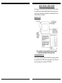
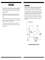
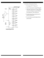
FIBERLINK®
XC-1000A, RC-1000A,
XC-1000A/MCR, RC-1000A/MCR
Status/Contact Closure Control System
USER’S MANUAL
55 Cabot Court
Hauppauge, N.Y. 11788 USA
TEL: (631) 273-0404 • FAX: (631) 273-1638
INTERNET: http://www.commspecial.com
EMAIL: [email protected]
P/N: 101961 Rev. '
CONTENTS
Quick Installation Guide ................................................................................... 2
General Information ......................................................................................... 3
Introduction
Technical Specifications
Theory of Operation
Functional Block Diagram
Installation Instructions for XC-1000A ............................................................ 6
Installation Procedure
Signal and Power Connections
Operating Pointers
Installation of XC-1000A/MCR
Installation Instructions for RC-1000A ............................................................ 9
Installation Procedure
Signal and Power Connections
Operating Pointers
Installation of RC-1000A/MCR
Interface Troubleshooting ............................................................................... 12
Operating Considerations for Fiber Optic Cable ............................................ 14
Overall System Checkout and Troubleshooting Techniques .......................... 16
Maintenance ................................................................................................... 19
Statement of Warranty .................................................................................... 20
1
QUICK INSTALLATION GUIDE
The following is a quick installation guide for the Fiberlink XC and RC-1000A.
It is intended for users familiar with the installation of fiber optic transmission
systems to get “up and running” in minimal time. For additional details, please
consult the balance of this manual.
Stand-Alone Unit
Card-Cage Mountable Unit
The Fiberlink XC-1000A/MCR and RC-1000A/MCR are designed to plug directly
into an available slot in the MCR-1000A rack mountable card cage. When this is
done, all operating power is provided by the MCR-1000A.
2
GENERAL INFORMATION
WARRANTY
Introduction
The Fiberlink XC-1000A is a multiplexed digital transmitter that will convert up to
8 channels of individual contact closures or TTL signals to modulated light
which can then be sent over a fiber optic cable.
The RC-1000A is a digital demultiplexing receiver that will convert the modulated
light from an XC-1000A back into 8 individual contact closures or TTL signals,
corresponding to the contact closures in the transmitter.
The XC-1000A/MCR is a card cage mountable version of the XC-1000A. The
RC-1000A/MCR is a card cage mountable version of the RC-1000A. Both are
designed to mount in a standard Communications Specialties MCR-1000A card
cage enclosure. All specifications, instructions and details in this manual apply
to all versions of these units.
Technical Specifications
Number of Channels ..................................... 8
Speed of Response (per channel) ................. 2.0 milliseconds typ.
Transmit Signal ............................................. Dry Contact Closure or TTL input
Logical “1” Input (When TTL) .................... 2.5V min. 5.5V max.
Logical “0” Input (When TTL) .................... 0.8V max. 0V min.
Receive Signal .............................................. Dry Contact Closure or TTL output
Logical “1” Output (When TTL) .................. 2.4V min. 3.3V typ.
Logical “0” Output (When TTL) .................. 0.4V max. 0.2V typ.
Receive Contact Rating
0.5 ampere, resistive, 100volts
peak, maximum
Optical Loss Budget ..................................... 50u Fiber, 0-8 dB
62.5u Fiber, 0-10 dB
8/10u SM Fiber, 0-10 dB
Operating Wavelength .................................. 850 nm or 1310 nm
Optical Connectors ....................................... ST, multimode
FCPC, single mode
Operating Temperature ................................. -20 to +50 degrees C
3
Communications Specialties warrants that for a period of three years after
purchase by the Buyer, all Fiberlink® transmission systems will be free from
defects in material and workmanship under normal use and service. A Return
Material Authorization (RMA) number must be obtained from Communications
Specialties before any equipment is returned by the Buyer. All material must be
shipped to Communications Specialties at the expense and risk of the Buyer.
Communications Specialties’ obligation under this warranty will be limited, at its
option, to either the repair or replacement of defective units, including free
materials and labor. In no event shall Communications Specialties be
responsible for any incidental or consequential damages or loss of profits or
goodwill.
Communications Specialties shall not be obligated to replace or repair
equipment that has been damaged by fire, war, acts of God, or similar causes, or
equipment that has been serviced by unauthorized personnel, altered,
improperly installed or abused.
RMA numbers and repairs can be obtained from:
Communications Specialties, Inc.
55 Cabot Court
Hauppauge, N.Y. 11788 USA
Tel: (631) 273-0404.
FAX: (631) 273-1638
Internet: www.commspecial.com
Email: [email protected]
Please have your serial number available when contacting us.
20
MAINTENANCE
The Fiberlink XC-1000A and RC-1000A have been manufactured using the latest
semiconductor devices and techniques that electronic technology has to offer.
They have been designed for long, reliable, and trouble free service and are not
normally field repairable.
Should difficulty be encountered, Communications Specialties maintains a
complete service facility to render accurate, timely and reliable service of all
products.
The only maintenance that can be provided by the user is to ascertain that optical
connectors are free of dust or dirt that could interfere with light transmission and
that electrical connections are secure and accurate.
Theory of Operation
The Fiberlink XC-1000A first converts the individual contact closure inputs to a
TTL signal. This TTL signal is then applied to a digital multiplexer which
combines the eight inputs into a serial pulse train for transmission. When dry
contacts are used, they switch a reference 5 volt input to the respective channels. When TTL inputs are used, they are applied directly. The RC-1000A uses a
digital demultiplexer to recover the respective channels in the form of TTL
signals. These are then used to drive reed relays to provide the isolated dry
contact outputs. Since there is always a continuous pulse stream through the
multiplexer/demultiplexer combination, the loss of this pulse stream signifies a
loss of signal.
All other questions or comments should be directed to our Customer Service
Department. It should be noted that many “problems” can easily be solved by a
simple telephone call.
19
4
D. Check Receiver or Receiving Section of a Transceiver
1. Is the operating power (DC, AC, Voltages) correct?
5
2.
Are the correct pins on the connector or terminal block being used?
3.
Is light coming out of the fiber optic cable? This may be difficult to
see in many cases but dim glow may be present with 850nm light.
Other wavelengths such as 1310 nm are totally invisible.
4.
Is the optical connector on the receiver optical port clear of any
obstruction or minute dirt particles?
5.
Does it matter that the power ground and signal ground of many
systems are common?
18
B. Check Optical Connectors
INSTALLATION INSTRUCTIONS FOR XC-1000A
1.
Are the connectors are being used the correct size for the fiber being
used?
2.
Are the ends of the connectors free of all dust or dirt? If not, gently
clean the tip of the connector with a clean cloth or gauze moistened
with alcohol.
The Fiberlink XC-1000A is supplied ready for immediate operation. There are no
operating controls on the unit and no special user alignment procedure.
3.
Is the fiber broken in the connector? A quick inspection with an
inexpensive jeweler’s loop can determine this.
1.
4.
Is the fiber protruding from the tip of the connector? If so, refinishing
will be necessary.
It will be necessary to have a source of +10 to + 18 volts DC or 10 to 18
volts AC 50/60 Hz. Be certain to make all connections carefully and check
that the correct pins are being used.
2.
Connect the desired contacts to be used between the respective channel
input pin and the common voltage pin (pin 9). Alternately, connect the TTL
logic levels between the desired channel pin and the common ground pin
(pin 10).
Installation Procedure
Installation of the XC-1000A is as follows:
C. Check Fiber Optic Cable
1.
Is the fiber optic cable pulled too tightly around a sharp corner?
2.
Is the correct fiber size being used with the correct transmitter/receiver
combination?
3.
Check that when a contact is closed or a TTL logic “1” signal applied to a
channel pin, the proper channel indicator LED lights.
3.
Does the fiber pass light at all? A small penlight or flashlight can
usually be used for this test.
4.
When the above has been achieved, the XC-1000A is ready for operation.
4.
Does the fiber have too much attenuation for the system? The attenuation measured on the reel will always be different after the cable is
installed.
5. When using very short lengths, less than 10 meters (30 feet), overloading of the receiver may occur. The shorter the length of the fiber, the
greater the possibility for this condition. Be sure there is adequate
attenuation in any system. If this seems to be the case, or if operation
with a meter or so of fiber is required, contact the factory.
17
Note: The transmitting element in the “-7” single-mode
version of the XC-1000A uses a solid state Laser Diode
located in the optical connector on the unit. This device
emits invisible infrared electro-magnetic radiation
which can be harmful to human eyes. The radiation
from this optical connector, if viewed at close range
without a fiber optic cable connected to the optical
connector, may be of sufficient intensity to cause
instantaneous damage to the retina of the eye. As a
result, direct viewing of this radiation should be avoided
at all times.
6
Signal and Power Connections
OVERALL SYSTEM CHECKOUT AND
TROUBLESHOOTING TECHNIQUES
DB-25 Signal Connector
Channel 1
Pin 1
Channel 2
Pin 2
Channel 3
Pin 3
Occasionally, during the installation of a fiber optic system, difficulties arise that
are the result of factors beyond the control of the installer. It is to simplify the
task of the installer that the following general checkout procedure is included.
Channel 4
Pin 4
A. Check Transmitter or Transmit Section of a Transceiver
Channel 5
Pin 5
1.
Is operating power (DC, AC, Voltages) correct?
Channel 6
Pin 6
2.
Are the correct pins on the connector or terminal block being used?
Channel 7
Pin 7
3.
Is the correct signal level present at transmitter input?
Channel 8
Pin 8
4.
+ 5 volt reference
Pin 9
TTL input common
Pin 10
Does the transmitting LED glow dimly when a signal is applied? Note
that this is only true for an operating wavelength of 850 nm. Units at
1310 nm are totally invisible.*
The mating electrical connector for this system is an EIA standard, DB-25P.
5.
5 Pin Power Connector
If the unit is an analog or video transmitter (at 850 nm), is there a
continuous dim glow from the transmitting LED? *
6.
Is the optical connector on the transmitting LED clear of any obstruction or minute dirt particles?
7.
Does the fact that the power ground and signal ground of many systems
are common, matter?
8.
Does the fact that the power ground, signal ground, and case are
common cause a short circuit anywhere in the system?
PIN
FOR DC OPERATION FOR AC OPERATION
A
No Connection
10 to 18 volts 50/60Hz
B
+10 to +18 volts
No Connection
D
DC Common
AC Common
E
No Connection
No Connection
H
No Connection
No Connection
Please note that the AC and DC common is connected to the enclosure.
The mating power connector for this system is an Amphenol 126-223 or
equivalent.
* The above visual check should only be attempted with LEDs.
NEVER LOOK DIRECTLY AT AN OPERATING
LASER DIODE, REGARDLESS OF THE
OPERATING WAVELENGTH
US Government regulations require that all equipment using Laser Diodes be
clearly identified with warning labels. Be sure to heed these labels.
7
16
Notes Regarding Fiber Optic Cable
Operating Pointers
Multimode fiber optic cable contains an optical fiber with a light carrying “core”
that is only .0025 inches (62.5u) diameter. Single-mode fiber optic cable has an
even smaller “core”, only .00032 to .0004 inches (8-10u). This is smaller than a
human hair! Any minute particle of dirt or dust can easily block this fiber from
accepting or radiating light. As a result, the key word is cleanliness. Always use
the dust caps provided with all optical connectors whenever they are exposed to
air. Also, it is a good idea to gently clean the tip of an optical connector with
alcohol whenever dust is suspected.
Driving
Signal:
The input to the XC-1000A is TTL compatible with an input
impedance of about 3k ohms per channel. A +5 volt input
(or TTL logic “1” level) indicates a closed contact, while a 0
volt input (or TTL logic “0” level) constitutes an open.
External contacts connected to this unit actually switch the 5
volt reference source into the input pins.
Indicator
LEDs
The actual status of the individual input channels is indicated
by the eight indicator LEDs on the unit. An LED that is on
indicates a closed contact, while an LED that is off indicates
an open contact.
Power
Supplies:
The DC power input to the XC-1000A is connected to an
internal 3 terminal regulator. Input can therefore be unregulated
DC from +10 to +18 volts. Any ripple voltage must not drop
below +10 volts however.
Mechanical butt splices or optical feedthroughs must be installed properly.
Multimode devices will not operate properly with single-mode devices even
though they may look the same. Using the wrong device can easily add more
attenuation than specified with the result that performance will suffer.
The AC input to the XC-1000A is connected to a half wave
rectifier and regulator that produces +10 volts internally. Input can
therefore be anything between 10 and 18 volts AC 50/60 Hz. This
voltage can be obtained from an inexpensive transformer or an XP1000 115 volt to 14 volt plug-in adapter if desired.
Optical
Fiber:
Versions of the XC-1000A are available to drive most multimode
(MM) and single-mode (SM) optical fibers. The specific models
are identified by a suffix at the end of the model number as
follows:
Fiber Size
50u, 62.5u MM
8/10u SM
Connector
850nm
130nm
ST
FCPC
-1
-
-3
-7
Installation of the XC-1000A/MCR
The XC-1000A/MCR is exactly the same as the XC-1000A except that it is
packaged for use in the MCR-1000A card cage. Installing the unit entails
simply plugging it in a free slot. All operating power is then provided by the
MCR-1000A Signal; connections are the same as for the XC-1000A.
15
8
INSTALLATION INSTRUCTIONS FOR RC-1000A
Installation Procedure
The RC-1000A is usable over an optical attenuation range that is a function of
fiber core size. Since all installations have attenuation levels that vary due to
fiber attenuation, it will be necessary to adjust the unit to compensate for the
length of optical fiber being used. To do so entails the following procedure:
1.
It will be necessary to have a source of +10 to +18 volts DC or 10 to 18
volts AC 50/60 Hz. Be certain to make all connections carefully and to
check that the correct pins are being used.
2.
Turn the adjustment control, located near the optical connector on the
housing, fully counterclockwise (25 to 30 turns will assure this).
3.
Connect the fiber optic cable to be used in the system from an operating
XC-1000A transmitter to the RC-1000A and activate the contacts
corresponding to channel 1 on the XC-1000A.
4.
Connect an ohmmeter between the output contacts of channel 1 on the
RC-1000A.
5.
Slowly turn the adjustment control on the RC-1000A until the contacts for
channel 1 just close. Then turn the control 1/4 turn further.
6.
Check that the LED indicating the status of channel 1 on the RC-1000A is
also lit.
7
Repeat this procedure to be certain that the other channels operate
properly.
8.
This completes alignment of the receiver.
OPERATING CONSIDERATIONS FOR
FIBER OPTIC CABLE
The XC/RC-1000A series may be supplied with ST or FCPC type optical
connectors, and will operate with most common fiber optic cables.
Since the system can be provided for operation at a wavelength of 850nm or
1310nm, the fiber optic cable employed should be chosen so that it is optimized
for use at the appropriate wavelength.
Due to the small size of the actual optical fiber, correct alignment is imperative.
When using any type of fiber optic cable be certain to not cause excessive
strains especially at the cable-to-connector junctions. Also, do not subject the
cable to sharp bends or pull around sharp corners. Whenever possible, service
loops or extra slack should be provided in any installation. While excessive
precautions are not necessary, fiber optic cable should be treated with moderate
care as it does contain thin, fragile strands of glass.
Pin H on the 5 pin power connector can be used as a loss of signal or “broken
fiber” detector. It is an open collector that will conduct (with respect to pin D)
when the signal being received by the RC-1000A is interrupted or lost. Up to 25
milliamperes (+) of current can be accommodated by this pin from a source of
up to +25 volts DC.
9
14
RC-1000A
Signal and Power Connections
Each channel’s output from the RC-1000A is a “floating” dry contact closure
from a small internal reed relay that is isolated from all other points of the
circuit.. These contacts are rated at 0.5 amperes, resistive, and must not be
overloaded or they will fuse and stick. In addition, the open circuit contact
rating of 100 volts must not be exceeded.
DB-25 Signal Connector
The TTL output from each channel is designed to drive one TTL load. The use
of more than one may cause the output to not perform properly.
The alarm output consists of an open collector that conducts upon loss of signal.
This collector is rated at 25 milliamperes and is not reverse polarity protected so
it is extremely important to check all connections carefully.
Channel 1
Channel 2
Channel 3
Channel 4
Channel 5
Channel 6
Channel 7
Channel 8
TTL output common
Contacts
Pins 1, 2
Pins 3, 4
Pins 5, 6
Pins 7, 8
Pins 9, 10
Pins 11, 12
Pins 13, 14
Pins 15, 16
TTL
Pin 17
Pin 18
Pin 19
Pin 20
Pin 21
Pin 22
Pin 23
Pin 24
Pin 25
The mating electrical connector for this system is an EIA standard, DB-25P.
5-Pin Power Connector
PIN
FOR DC OPERATION FOR AC OPERATION
A
No Connection
10 to 18 volts 50/60Hz
B
+10 to +18 volts
No Connection
D
DC Common
AC Common
E
No Connection
No Connection
H
Loss of Signal Detector
Loss of Signal Detector
Pin H can be used as a loss of signal or “broken fiber detector” on the RC1000A. It is not used or connected on the XC-1000A. In operation, when the
signal is lost (usually caused by a fiber break), pin H, which is an open collector,
will conduct with respect to pin D. This pin will sink up to 25 milliamperes
from a source of up to 25 volts DC. This output is also not reverse polarity
protected so it is important to be extremely careful when making connections.
Please note that the AC and DC common is connected to the enclosure.
The mating power connector for this system is an Amphenol 126-223 or
equivalent.
13
10
Operating Pointers
Installation of the RC-1000A/MCR
Output
Signal:
The RC-1000A/MCR is exactly the same as the RC-1000A except that it is
packaged for use in the MCR-1000A card cage. Installing the unit entails
simply plugging it in a free slot. All operating power is then provided by the
MCR-1000A signal; connections are the same as for the RC-1000A.
The contact closure output signal of the RC-1000A is provided by
reed relay contacts that are isolated from any other part of the
circuit. The 0.5 ampere ratings of these contacts must not be
exceeded.
External relay coils driven by the RC-1000A must have back EMF
diodes installed across their coils or damage to the RC-1000A will
occur and void any existing warranty.
INTERFACE TROUBLESHOOTING
The TTL outputs are provided by standard TTL drivers.
XC-1000A
Indicator
LEDs:
The output status of the RC-1000A channels are monitored by eight
indicator LEDs. ON indicates that the contacts for a particular
channel are closed, OFF indicates that they are open.
The input to the unit must be a dry contact or a TTL signal. If it is a dry contact,
it must switch a +3 to +5 volt level into the input. The sketch below shows both
the suggested contact arrangement or the TTL input.
Power
Supplies:
The DC power input to the RC-1000A is connected to an internal 3
terminal regulator. Input can therefore be unregulated DC from
+10 to +18 volts. Any ripple voltage must not drop below +10
volts however.
Non-dry contact closures (with other voltages) will not work and may damage
the input.
The AC input to the RC-1000A is connected to a half wave rectifier
and regulator that produces +10 volts internally. Input can therefore be anything between 10 and 18 volts AC 50/60 Hz. This
voltage can be obtained from an inexpensive transformer or an XP1000 115 volt to 14 volt plug-in adapter if desired.
Optical
Fibers:
Versions of the RC-1000A are available to operate with most
multimode (MM) and single-mode (SM) optical fibers. The
specific models are identified by a suffix at the end of the model
number as follows:
Fiber Size
50u, 62.5u MM
8/10u SM
Connector
850nm
130nm
ST
FCPC
-1
-
-3
-7
11
If an external 3 to 5 volt source is used, its common would be to pin 10.
12