1
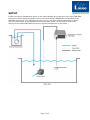
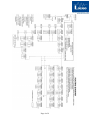
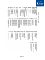
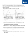
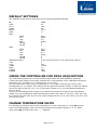
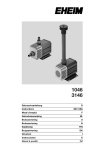
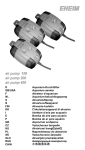
TMP-REG with TMP-SET (optional)
Temperature Analyzer and Regulator System
User manual version 2.4
The TMP-REG system is used for monitoring and regulating water temperature of sea or fresh
water in fish tanks, respirometers, aquaria etc.
LIST OF PARTS
1)
2)
3)
4)
5)
6)
7)
Controller instrument
Data Cable
Pt100 temperature probe
Power cord
Converter piece
User manual
TMP-SET (OPTIONAL)
- Submersible Eheim pump
- Adapter cable for pump
- Soft PVC tubing
- Stainless steel cooling coil
CONTENTS
LIST OF PARTS .............................................................................................................. 1
CONTENTS ................................................................................................................... 1
CONFIGURATION / OPERATING THE FUNCTION KEYS ........................................................ 3
USING THE RELAYS ....................................................................................................... 6
FAST SET POINT ADJUSTMENT ........................................................................................ 3
PASSWORD PROTECTION ............................................................................................... 7
DEFAULT SETTINGS ....................................................................................................... 8
USING THE CONTROLLER FOR DATA ACQUISITION ........................................................... 8
CHANGE TEMPERATURE UNITS........................................................................................ 8
TMP-REG SPECIFICATIONS ............................................................................................. 9
Page 1 of 9
SETUP
Connect the Pt100 temperature probe to the input labelled IN on the front side of the TMP-REG
instrument. Now connect the power cord to the input labelled POWER on the backside of the
TMP-REG instrument. The TMP-REG will now turn on, and start reading temperature values.
There are two relays on the backside of the instrument which can be used to control the
activity of the submersible Eheim pump to regulate temperature in the water.
Page 2 of 9
CONFIGURATION / OPERATING THE FUNCTION KEYS
The TMP-REG is a menu-driven instrument. The front panel has three buttons for operation,
e.g. two arrow buttons (Λ and V) and one OK button. Use these three buttons to scroll
through the menu and accept instrument settings. For each menu there is a scrolling help text
which is automatically shown in the display, this starts after five seconds if no key has been
activated. Use the menu to calibrate the temperature probe, and set relay action and level of
control.
Λ
V
OK
will increase the numerical value or choose the next parameter.
will decrease the numerical value or choose the previous parameter.
will accept the chosen value and end the menu.
To summarize, the Λ and V buttons are used to toggle betweens options. The OK button is
used to accept settings and go to the next option. Press and hold the OK button for 0.5
seconds, to get the last option available. Once the entire configuration has been entered, the
display will show “----”.
The following two pages show the complete menu routing diagram and scrolling help texts.
NB! Please note that the TMP-REG is password protected. The Password is 1234. The RE1 is
set to act on a decreasing signal, the RE2 is set to act on an increasing signal. Use the fast set
point adjustment to adjust the set point.
FAST SET POINT ADJUSTMENT
It is possible to quickly change set point values without having to scroll through the whole
instrument menu.
With the instrument turned on, press the Λ button once. Now choose relay 1 (or 2), and press
the OK button. Then change the set point value using the arrow buttons. Finish by pressing
the OK button.
Test relay functions, by pressing both arrow buttons simultaneously. The LED diode will toggle
its state. When done, press the OK button several times until the display reads “----”.
Page 3 of 9
Page 4 of 9
Page 5 of 9
USING THE RELAYS
The TMP-REG instrument has two independent relays to control the activity of submersible
pumps. For each relay choose a set point and a hysteresis value. Now decide if the relay
should be activated when the signal drops below a set point (DECR), or if it should be activated
when it rises above (INCR), e.g. for cooling control the relay should act on a increasing (INCR)
signal, since temperature will increase above the set point due to heating effects in the
chamber, e.g. sun shining.
Example – how to keep temperature low despite warming effects
Set up the TMP-REG system in the following way, to keep temperature at say 15 °C in aquaria
due to warming effects from sun shining and heating from pumps.
1. Connect the submersible Eheim pump to relay 1 on the back side of the TMP-REG
instrument (relay 2 is not used in this example).
2. Connect the coil to the output of the submersible Eheim pump via the tubing. Use so
much tube, that the coil can be placed in the cooling bath.
3. Place the coil into the cooling bath. Make sure that the temperature of the cooling bath
is cooler than the wanted Setpoint (15 °C), e.g. water with ice cubes.
4. Connect to the coil the remaining tubing and place the tubing into the aquaria. Now,
when the relay turns on, the submersible pump will suck water from the aquaria and
pump it through the coil. While water is pumped through the coil, the water will be
cooled down. So the water that is pumped back into the aquaria is cooled.
Instrument settings
5. Press the OK button several times until the display reads REL1. Wait for one second,
and the display now reads SET, or toggle using arrow buttons until it reads SET, and
then press OK.
Page 6 of 9
6. Now use the Λ or V buttons to increase or decrease the set point value. Set it to 15
(°C), and then press OK.
7. Set the action of the relay to INCR, and then press OK.
8. Now enter the hysteresis value. Use arrow buttons to set the value to 0,5 (°C), and
then press OK.
9. Press OK several times, until the display reads “----“ to finish.
Relay 1 will be activated every time temperature rises above 15 °C, pumping water through
the coil.
This will cause the temperature of the water to decrease, and as it reaches 14,5 °C the relay
de-activates. After some time temperature will rise above 15 °C again due to heating effects,
and relay 1 is activated once more.
In this way, temperature in the aquarium is automatically kept at 14,5-15 °C at all times.
PASSWORD PROTECTION
Using a password will stop access to some of the menu and parameters. There are two levels
of password protection. Passwords between 0000-4999 will allow access to the fast set point
adjustment and relay test. (Using this password stops access to all other parts of the menu).
Passwords between 5000-9999 stop access to all parts of the menu, fast set point and relay
test. (Current set point is still shown). By using the master password 2008, all configuration
menus are available.
If you want to enable password protection, press the OK button several times, until the display
reads E.PAS. Use an arrow button to choose YES, and then press OK. Now set the password
using the arrow buttons, and press OK when done. If you want to disable password protection,
go to the menu option E.PAS. again and set it to NO. Finish by pressing the OK button.
Page 7 of 9
DEFAULT SETTINGS
The TMP-REG instrument is delivered with the following default settings:
IN:
TYPE
PT.TY
CONN
DEC.P:
UNIT
REL1
TEMP
PT
100
4W
111.1
°C
SETP
ACT
HYS
ERR
ON.DE
OF.DE
25.0
DECR
0.5
HOLD
0
0
REL2
SETP
ACT
HYS
ERR
ON.DE
OF.DE
ANALOG OUTPUT:
0.LO
0.HI
0.ERR
RESP
E.PASS
N.PASS
25.0
INCR
0.5
HOLD
0
0
4-20 (converted into a 0-5V instrument output)
0
100
3.5mA
1.0
YES
1234
USING THE CONTROLLER FOR DATA ACQUISITION
The instrument produces a 0-5 Volts analog output signal for data acquisition purposes.
Connect the data cable to the socket marked Out on the backside of the TMP-REG instrument.
Connector pin 1 is positive (+), connector pin 4 is 0 (zero).
The low instrument value (0.LO) corresponds to a 0 V output, and the high value (0.HI)
corresponds to a 5 V output. This means, that the gain becomes HI value/5 V. With the default
values the gain is then 20 °C/V, e.g. if the output voltage is 4 V, the calculated temperature
value is 80 °C.
If the 0-5 Volt analog signal is noisy try to shorten the range of interest of the temperature
output. E.g. the temperature signal will always be within the range of 15-25°C. Then set 0.LO
to 15 and 0.HI to 25. Now the 0-5 Volt output voltage will be 0 V at 15°C and 5 V at 25°C. The
gain will be 2°C/V.
CHANGE TEMPERATURE UNITS
It is possible to measure and control temperature in other units than °C. Press OK several
times until UNIT appears. Now use the Λ or V buttons to toggle between °C or °F. When
done, press OK several times until “----“ appears.
Page 8 of 9
TMP-REG SPECIFICATIONS
Supply voltage (universal):
Internal consumption:
Max. consumption:
Isolation voltage (test / operation):
Signal- / noise ratio:
Response time, programmable:
Calibration temperature:
Accuracy:
Temperature Coefficient:
EMC immunity influence:
Potentiometer input, min:
Potentiometer input, max:
Relay function:
Hysteresis, in % / display counts:
On and Off delay:
Sensor error detection:
Max. voltage:
Max. current:
Max. AC power:
Max. current at 24 VDC:
21.6-253 VAC, 50-60 Hz or 19.2-300 VDC
3.2 W
3.5 W
2.3 kVAC / 250 VAC
Min. 60 dB (0-100 kHz)
0.4-60 s
20-28°C
≤±0.1% of reading
≤±0.01% of reading/ °C
≤±0.5% of reading
10 Ω
100 kΩ
Setpoint
0.1-25% / 1-2999
0-3600 s
Make / Break / Hold
250 VRMS
2 A / AC
500 VA
1A
IMPORTANT: DO NOT connect relays to >500W equipment (max 2 A, 250 V).
Marine approval
Det Norske Veritas, Ships & Offshore
Standard for Certification No. 2.4
Observed authority requirements:
Standard: EMC 2004/108/EC
Emission and immunity
EN 61326
LVD 73/23/EEC
EN 61010-1
UL, Standard for Safety UL 508
Page 9 of 9