1
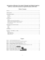
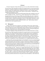
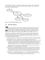
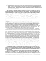
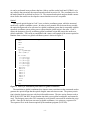
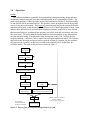
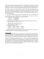
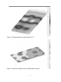
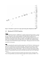
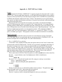
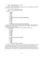
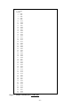
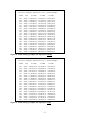
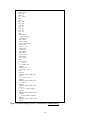
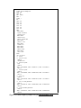
NASA Technical Memorandum 110153
Integration of Design, Structural,
Thermal and Optical Analysis
and User’s Guide for Structural-to-Optical Translator
(PATCOD)
R. M. Amundsen, W. S. Feldhaus, A. D. Little, and M. V. Mitchum
Langley Research Center, Hampton, Virginia
March 1995
National Aeronautics and
Space Administration
Langley Research Center
Hampton, Virginia 23681-0001
Integration of Design, Structural, Thermal and Optical Analysis
and User’s Guide for Structural-to-Optical Translator (PATCOD)
Table of Contents
Abstract ......................................................................................................................................................... 1
1.0 Background ............................................................................................................................................. 1
2.0 Model Development................................................................................................................................. 2
Thermal...................................................................................................................................................... 2
Structural ................................................................................................................................................... 3
Optical ....................................................................................................................................................... 4
3.0 Operation................................................................................................................................................. 5
Outline ....................................................................................................................................................... 5
Interfaces between Design and Analysis ..................................................................................................... 6
Interface between Thermal and Structural Analysis .................................................................................... 6
Exporting Structural Results to Optical Analysis ........................................................................................ 7
Pictorial Example....................................................................................................................................... 8
4.0 Running the PATCOD Translator........................................................................................................ 10
Purpose.................................................................................................................................................... 10
Input......................................................................................................................................................... 10
Output ...................................................................................................................................................... 11
5.0 Summary................................................................................................................................................ 11
Appendix A: PATCOD User’s Guide ........................................................................................................ 13
Purpose.................................................................................................................................................... 13
Input Requirements .................................................................................................................................. 13
Output Requirements ................................................................................................................................ 15
Sample Execution..................................................................................................................................... 15
Figures
Figure 1. Overall integrated analysis process ................................................................................................ 2
Figure 2. Macro for translation from relative to global coordinates............................................................... 4
Figure 3. Process flow for integrated design/analysis at LaRC....................................................................... 5
Figure 4. Thermal gradients on optical bench (in °C) .................................................................................... 9
Figure 5. Structural x-deflections due to thermal load (in meters).................................................................. 9
Figure 6. Translation to optical code: single optical beam path with deflection in mm.................................. 10
Figure 7. Sample relational file: PATHS.DAT............................................................................................... 16
Figure 8. Partial listing of sample run input file: tran.prt ............................................................................. 17
Figure 9. Partial listing of sample run input file: rot.prt ............................................................................... 17
Figure 10. Partial listing of Code V runstream file: samplerun.seq ............................................................... 18
Figure 11. Partial output of sample run, file opticalrunDEF1.SEQ ............................................................... 19
Figure 12. Sample Execution Run of PATCOD ............................................................................................ 20
-i-
Abstract
Electronic integration of design and analysis processes was achieved and refined at Langley
Research Center (LaRC) during the development of an optical bench for a laser-based aerospace
experiment. Mechanical design has been integrated with thermal, structural and optical analyses.
Electronic import of the model geometry eliminates the repetitive steps of geometry input to
develop each analysis model, leading to faster and more accurate analyses. Guidelines for integrated model development are given.
This integrated analysis process has been built around software that was already in use by designers and analysts at LaRC. The process as currently implemented uses Pro/Engineer for design, Pro/Manufacturing for fabrication, PATRAN for model building and results visualization,
NASTRAN for structural analysis, SINDA-85 and P/Thermal for thermal analysis, and Code V
for optical analysis. Currently, the only analysis model to be built manually is the Code V model;
all others can be imported from the Pro/Engineer geometry. The translator, PATCOD, was developed and tested at LaRC to transfer PATRAN results to Code V optical analysis software.
Directions for use of the translator are given.
1.0
Background
In many industries there has recently been a concerted movement toward “quality management” and the issue of how to accomplish work more efficiently. Part of this effort is focused on
concurrent engineering: the idea of integrating the design and analysis processes so that they are
not separate, sequential processes (often involving design rework due to analytical findings) but
instead form an integrated system with smooth transfers of information.
Electronic integration of design and analysis processes was achieved and refined at Langley
Research Center (LaRC) during the development of an optical bench for a laser-based aerospace
experiment. One of the driving requirements for any complex optical system is its alignment
stability under all conditions. Accurate predictions of optical bench or test bed deflections are
necessary to calculate beam paths and determine optical performance. Another requirement
increasingly demanded of any analysis process is to do it faster and better; create a more streamlined process and include all known variables to produce the best possible predictions. These
goals can be accomplished by using an integrated process to accomplish design and all analyses.
The heart of the concurrent engineering process described here is the use of a single integrated
model for thermal and structural analysis of a system. This allows a saving of time in the thermal
and structural analysis work, since only one geometric model must be developed. It facilitates
electronic transfer of data between all types of analysis, such as transfer of exact thermal gradients
to be used in structural analysis. Finally, it produces greater model accuracy since the model can
be directly imported from the design software package.
This integrated analysis process has been built around software that was already in use by de®
signers and analysts at LaRC. The process as currently implemented at LaRC uses Pro/Engineer
for design, Pro/Manufacturing for fabrication, PATRAN for model building and results visualization, NASTRAN for structural analysis, SINDA-85 and P/Thermal for thermal analysis, and Code
V for optical analysis. At the present time, the only analysis model that must be built manually is
the Code V model -- all others can be imported from the Pro/Engineer geometry. The results
from the thermal and structural analyses can be exported to Code V to produce optical analyses
based on the predicted deflections due to temperature and load distributions. Most of these inte-1-
gration and interface steps are also possible with other packages, although some of the translators
were developed or modified for use with these specific software packages. The overall method
used at LaRC is depicted in Figure 1.
Pro/Engineer
design
PATRAN
modeling and
results visualization
ly
on
lts
su
re
SINDA-85
thermal analysis
NASTRAN
structural analysis
CODE V
optical analysis
Figure 1. Overall integrated analysis process
2.0
Model Development
Thermal
There are several rules that must be followed in building a PATRAN model that can be used
for both thermal and structural analyses. The most important is that the analysts communicate
before the model is built to ensure that all requirements on the model are considered. The rules
listed below may change as the PATRAN software changes, but are always good things to consider. If not noted otherwise, these apply to both PATRAN 2.5 and PATRAN 3 (P3). The
methods have some differences, since PATRAN 2.5 uses the elements of the model as thermal
nodes, and thus the temperatures must be extrapolated to the structural nodes. PATRAN 3 uses
the finite element nodes as the nodes of the thermal model. The following are key items for correct operation of the thermal translator:
• Solid elements that are to connect must have four identical corner nodes on the face they share.
• Plate elements that are to connect must have two identical corner nodes on the edge they share.
• In PATRAN 2.5, no plate can attach to a solid element using less than four nodes.
• In PATRAN 2.5, a plate attached to a solid element using four identical corner nodes will create
a thermal conductor that does not include the conduction through the thickness of the plate.
An additional connection here must be constructed by the thermal analyst using a DFEG
command to get the correct value. In PATRAN 3, this problem does not arise since the finite
element nodes are used as the nodes of the thermal model. Thus, in the case of a plate attached to the face of a solid, the nodes would coincide.
• In PATRAN 2.5, all the material property values must be reset when the model is transferred
between structural and thermal analysis, because the thermal properties overwrite the structural properties and vice versa. In P3, the properties are currently overwritten in a transfer
between structural and thermal analysis; this is slated to be improved in future versions.
• In PATRAN 2.5, when three plates connect as a “T,” a bar element must be added at the
intersection to keep the thermal conduction correct. Likewise, when three bars connect as a
“T,” a point element must be added to keep the thermal conduction correct.
-2-
• The thermal analyst may need to reference either element or node numbers later in the thermal
model; a record of element numbers in the model is desirable, as is keeping the numbering sequential and simple. Again, the analysts should communicate to establish a method for recording model-related information.
One way to use the nodes and conductors created by PATRAN is to separate them into files
that are called into the SINDA model using INCLUDE statements. Thus the SINDA model can
contain other data such as heating arrays; if there is a change to the PATRAN model it will only
affect the included files, with the main SINDA model left unchanged. The output of the
PATRAN-to-SINDA translator is often quite bulky, which makes editing of the full SINDA
model difficult. Using included files limits the size of the SINDA model file, and allows several
different SINDA files to reference the same PATRAN model. If P3/Thermal is used, all data are
contained in the PATRAN model, and there is usually no need for manual editing of files.
Structural
The structural deflection translated to the optical model is only that due to the distortion of
the optical bench or supporting structure, and to deflections of the optical component mounts.
Currently, distortions of a single optical component are not included in this translator. Reasons
for this are two-fold: (1) a detailed translator for single optical component distortion already
exists between NASTRAN and Code V; and (2) in the particular application for which this translator was developed, the distortion of the supporting structure was the dominating factor. The
supporting structure is also the dominating factor in many common applications.
Each optical surface is modeled as an individual node in the structural model. Some of the
optical components may require several nodes to represent different locations on a single component. For example, a lens that would normally only be a single node in PATRAN might require
three surfaces in Code V (front surface, center, back surface). Each of these surfaces should then
be a separate node in the PATRAN model, positioned in the same locations as the Code V surfaces. The connection between nodes should be rigid, although it can simulate the coefficient of
thermal expansion of the optical material, if desired. If the separate nodes comprising a single
optical component are not structurally connected together, or are modeled as a single node in
PATRAN, errors will arise in the translation of results to the optical model. If the surfaces are
modeled as a single node, then the surfaces of the component will not remain aligned when the
structural results are translated to Code V. The reason for this is that any rotation of a twosurfaced optical component (such as a lens or beamsplitter) imparts differing translations to the
front and back surfaces. With the component modeled as a single node, the translations due to
rotation will be the same, which is not physically correct. If the nodes are not connected together
structurally, but instead are each connected separately to the optical bench, there is no way to
ensure that the translations of the front and back surfaces of each element remain aligned.
In this particular model, the connected nodes are attached to the optical deck by three rigid
elements. The structural analyst may select any method of attaching the nodes to the supporting
structure. The connection of the nodes to the supporting structure should simulate the stiffness of
the optical mount.
The PATRAN user should keep all of the optical nodes together in a named component (in
PATRAN 2.5) or in a group (in P3). This enables the user to easily specify these nodes in the
results post-processing phase. The method for writing out the structural data from PATRAN in a
format acceptable to the optical translator PATCOD is described in section 4.0. Structural analy-3-
sis can be performed in any software that has a link to read the results back into PATRAN, or in
any software that can mimic the output format described in section 4.0. The coordinate axes for
the model should be as defined in section 3.0. The structural and optical analysts should communicate before the models are developed to ensure that these axes are acceptable.
Optical
The typical optical design in Code V uses a relative coordinate system, while the structural
model uses a global coordinate system. In order to easily transfer files between the two models,
the optical design needs to be converted to a global coordinate system that is compatible with the
structural coordinate system, taking care to ensure that the global origin is the same. Code V
allows the designer to specify an arbitrary global coordinate origin and convert the surfaces to
global coordinates. This can be accomplished with a macro; an example of the macro required to
translate from a relative to a global coordinate system is shown in Figure 2.
Macro to convert a surface to a GLB (global decentered) surface
ver n
rfd 0 0
ver n
ins s1 0 0
ins si 0 0
^g == 1 ! global origin
^surf == (num s) - 1
for ^s 2 ^surf
^x == (xsc s^s g^g)
^y == (ysc s^s g^g)
^z == (zsc s^s g^g)
^a == (asc s^s g^g)
^b == (bsc s^s g^g)
^c == (csc s^s g^g)
glb s^s g^g
xde s^s ^x
yde s^s ^y
zde s^s ^z
ade s^s ^a
bde s^s ^b
cde s^s ^c
sur s^s
end for
ver y
Figure 2. Macro for translation from relative to global coordinates
The translation to global coordinates does impose some restrictions on the commands used to
generate the optical design that the optical designer must take into account. The primary restriction is that the designer must use only basic tilts and decenters. The time saving features such as
BEN, DAR, RET, and REV do not translate into their correct global coordinates, and cannot be
used. The designer can use the GSC command to verify that the converted file matches the original file. Once the file has been converted to global coordinates, it is written to a sequence file.
The sequence file is in the format required by the translator program (PATCOD).
-4-
3.0
Operation
Outline
The software translators responsible for accomplishing translations among design and structural/thermal analytical models are in place and operational on SGI workstations at LaRC. The
model can be built in PATRAN by either analyst, then translated to SINDA-85 for thermal analysis and NASTRAN for structural analysis. The geometry can be brought in from the design software to create the model initially. There must be communication between the analysts before the
original model is built, so that the final model will have levels of detail appropriate for both. If the
analysts desire different levels of detail (thermal analysis commonly using a lower level of detail
than structural analysis), an identical base geometry can still be used and each analyst can create
their own mesh. The results from the thermal model are then interpolated to map temperatures
onto the structural model. The structural results are imposed on the Code V optical analysis
model by building a ‘deflected’ Code V model from an original undeflected model. The relationship between the structural and optical surfaces must be created as a separate file; the translator
does not have the capability (at this time) to build up the original Code V model from the
PATRAN model. The steps of this process are shown in Figure 3.
Design part
in Pro/Engineer
Import model to PATRAN
and mesh to create FEM *
Thermal analysis
in P/Thermal or SINDA-85
Import temperatures to PATRAN
and convert to thermal loads
Structural analysis
in NASTRAN
Import deflection
results to PATRAN
Develop CODE V
model*
Write out results files
from PATRAN
Develop relational file between
CODE V surfaces and PATRAN nodes
Run PATCOD
*
Axes and nodal
location information
should be coordinated
manually update part, model or
thermal conditions
based on optical performance
Run CODE V
on new model file
Figure 3. Process flow for integrated design/analysis at LaRC
-5-
Interfaces between Design and Analysis
The design software most often used in this process at LaRC is Pro/Engineer. A part is completely designed in Pro/Engineer, which produces a three-dimensional model of the part as well as
all the fabrication drawings. There are three basic methods available to translate from
Pro/Engineer CAD software to the PATRAN modeling software. All of these methods have been
used to produce viable models. One is to mesh the solid geometry of the part in Pro/Engineer and
translate that mesh to PATRAN. The disadvantages to this method are: only the mesh is transferred, not the underlying solid geometry, so the geometry and mesh cannot be changed in
PATRAN; and the mesh is limited to tetrahedral or triangular elements. The second method is to
transfer the part from Pro/Engineer to an Initial Graphics Exchange Specification (IGES) file, a
standard graphics format, and read this file into PATRAN. The disadvantages to this method
depend on the versions of software used. They can involve rework in creating the solid form from
the transferred surfaces, and reconstruction of an assembly from the component parts due to loss
of individual parts’ orientation during translation. The third (and optimal) method is to import the
geometry from a Pro/Engineer part file directly into PATRAN. This method is only viable for the
releases of Pro/Engineer above Version 10 and PATRAN 3 and above. The geometry can then be
either directly meshed, or used to create a PATRAN solid model. Options in Pro/Engineer and
P3 can be used to bring in simplified geometry (automatically deleting details such as bolt holes),
or to create a mid-plane shell geometry for a thin-walled part. Parts have also been imported into
PATRAN from ANVIL, but this brings across only the 2-D shape and position of parts.
The integration of design and analysis has several benefits. In terms of streamlining the process, there is much less work to be done by the analyst since the majority of the geometry is imported automatically. The entire process of taking dimensions from a design drawing and manually building up the model geometry is eliminated. Also, the analyst is automatically working with
the most current version of the design. Eliminating the repeated step of manually entering the
dimensions lessens the probability of errors in the model. Geometries that are difficult to model
and would perhaps be approximated are automatically translated exactly. If necessary, complex
geometries that are not needed by the analyst can be simplified before the model is meshed for
analysis.
Interface between Thermal and Structural Analysis
The translators between structural and thermal analytical models are already built into the
PATRAN system. The analysts can easily use the same geometric model, perform analyses
through their separate software packages, and share the results electronically. The model-building
techniques to make this type of translation easier and more effective are discussed in section 2.0.
To perform the thermal analysis, the PATRAN model can be translated to SINDA-85, a finite
difference thermal analyzer. For PATRAN 2.5, the PATSIN translator1 is used. For PATRAN 3,
the SINDA translator is built into PATRAN as part of the internal solver, P3/Thermal2. The
SINDA-85 model can be used to perform the thermal analysis, with some modifications such as
adding power sources. The thermal analysis can also be performed using P3/Thermal. The analysts often desire different levels of detail; thermal analysis commonly uses a lower level of detail
than structural analysis. The calculated temperatures can be used to impose accurate thermal
loads on the structural model regardless of whether the meshing is the same. This has been verified using two different meshings and element numbering schemes on a model; the interpolated
values were found to be correct. The thermal results, either from a steady state analysis or from
time steps in a transient run, can be read directly into PATRAN, and the thermal results mapped
-6-
onto the model geometry. For PATRAN 2.5 users, the output file from SINDA is translated by
SINPAT to produce element and nodal temperature files that can be read by PATRAN. For P3
users, either P3/Thermal or SINDA (using the RSPT85 subroutine) will produce nodal result files
that are directly readable by P3.
There are several methods available to import the nodal temperatures as actual thermal loads
for the structural analysis rather than only for display. For PATRAN 2.5 users, the files must be
run through a program called READER that translates the files to binary format. The results can
be interpolated onto the structural model using a built-in utility of PATRAN (TEMP,
ADD/INT)3. For P3 users, results from P3/Thermal or SINDA can be read into P3 using the file
import option. The temperatures are read in as a nodal results file using the appropriate template.
This data can be displayed on the finite element model as a fringe plot. This fringe plot is used to
create a continuous FEM field to apply the nodal temperature data as a structural thermal load.
Also, an option in PATQ (the P3 thermal executable program) allows users to map temperatures
from one model to another with a differing mesh. The latest PATRAN documentation should be
consulted for the most up-to-date method available.
The thermal results, imported into the PATRAN model, can be used in the structural analysis
software to calculate thermally driven stresses and deflections based on the predicted temperature
distribution. In this particular case, the structural analysis was performed in NASTRAN, but any
structural analysis software with an interface to PATRAN can be used. These thermal stresses
can be summed with any load-driven stresses, to produce a total reaction of the system to the
environmental constraints.
One advantage to the integrated method is the capability for viewing temperatures that are
mapped back onto the geometry of the part. This provides a concrete display that can be used for
demonstration of effects, or for de-bugging the model. An example is shown in the grey-scale
plot of Figure 4. The color temperature map can be animated to follow a time sequence of thermal events on a part4.
Exporting Structural Results to Optical Analysis
Most optical models start with the assumption that the system is aligned and at rest. The optical analyst inputs surfaces, sources and objects at their designed location, and determines the
performance of the system. The optical analysis code currently used by many analysts at LaRC is
®
Code V . During actual operation of the optical system, there will often be factors that cause
distortions to the aligned system. In the case of an optical bench with powered optical components mounted on it, there can be thermal gradients across the bench. These will cause minute
warping of the bench and result in significant distortion of the optical system from its baseline
aligned performance. There can also be structural loads imposed which cause deflections, and
both the thermal and mechanical loading environments can be changing with time. There is an
existing translator that will take the deformation of a single optical element such as a lens in
NASTRAN, and translate the appropriate information to Code V to determine the distorted lens
performance. However, for the optical bench structure, a method was needed to look at changes
in the overall performance based on distortions of the entire bench, not only a single element.
To accomplish this, an output file of nodal deflections is generated by the structural analysis
software, with six values for each optical surface (rotations and translations in each of three axes).
The deflections can be due to thermal, structural or any combination of loading conditions. A
relational file is developed for that model that relates the nodes in the PATRAN model to the
optical surfaces in the Code V model. Translation software (PATCOD) was developed at LaRC
-7-
which first reads the structural analysis deflection file, the relational file, and a copy of the undeflected Code V model. It then produces a new Code V model that has revised decenters and tilts
for the optical elements based on summing the predicted deflections and the original positions of
the elements. Code V is run on the new model file, and optical performance based on the distorted system is predicted. For any optical system there is usually only one PATRAN model, but
there can be a separate Code V model for each optical path. The translation must be run for each
optical path for which a deflection analysis is desired. The translation can be run for a series of
time steps, using deflection results files for each time step, to predict the performance of the system as a function of time.
The current translator assumes the following relationship between the axes of the global Code
V model and the axes of the PATRAN model. As mentioned earlier, the analysts should confer
before model development to determine the coordinate definitions.
X of Code V = -X of PATRAN
Y of Code V = -Y of PATRAN
Z of Code V = Z of PATRAN
The current definition of CODE V optical code global coordinate rotations is as follows:
Rotation around X (α): positive for Z-->Y
Rotation around Y (β): positive for X-->Z
Rotation around Z (γ): positive for X-->Y
Thus, rotations translate exactly:
PATRAN +X rotation = CODE V +X rotation
PATRAN +Y rotation = CODE V +Y rotation
PATRAN +Z rotation = CODE V +Z rotation
If the axes of the model to be translated do not correspond to these, the source code of the
PATCOD translator must be adjusted accordingly and recompiled.
Pictorial Example
The following figures show the process pictorially for an example optical bench. All figures
are grey-scale versions of color mappings and thus do not lend themselves to interpretation of the
exact numerical results. The figures are intended only to present a physical idea of the process.
Figure 4 shows the thermal results for a given set of conditions, including power to some optical
components. Only the optical bench itself is shown. Figure 5 shows the structural deflection in
reaction to those thermal loads, in the x-direction only. The irregular spots of reduced motion are
due to the presence of stiffening shear blocks within the optical bench. Figure 6 shows a single
optical path from the Code V model with the optical components and optical beam. The deflection of the beam is represented by the different shades of grey. The Code V model was imported
into P3 in order to view the deflection graphically.
-8-
Figure 4. Thermal gradients on optical bench (in °C)
Figure 5. Structural x-deflections due to thermal load (in meters)
-9-
Figure 6. Translation to optical code: single optical beam path with deflection in mm
4.0
Running the PATCOD Translator
Purpose
The translator PATCOD is a FORTRAN 77 computer program developed at LaRC. Its function is to read a typical Code V program optical model input runstream, update the decenter and
tilt values with the correction values generated by a structural analysis program such as
NASTRAN, and output the model in the Code V format. The program currently uses the structural analysis results in the format output by PATRAN. PATCOD has been compiled and executed on several computer systems: PC (DOS) using F77L compiler; SGI workstation (UNIX),
f77 compiler; and VAX/VMS minicomputer, FOR compiler. The program executes in seconds in
an interactive environment.
Input
Four external data files (details described in Appendix A, PATCOD User’s Guide) must exist
in the user’s local directory for execution to take place. One file, paths.dat, must be written by
the user in a specific format to describe the relationship of the path of optical surfaces to the
element node numbers in the structural analysis. There is no restriction on the number of paths
that may exist, but a maximum of 200 surfaces is imposed on each path (or the program must be
modified). The path chosen from the paths.dat file must be the same as the Code V path being
analyzed.
Two files are required to describe the translation and rotation decenter correction values.
These can be generated by any structural analysis program and are output by PATRAN 3. For
- 10 -
NASTRAN, results are translated from a NASTRAN ‘output2’ file into P3 under the analysis
menu. The user must specify in P3 that nodal rotations are required. This is accomplished by
checking the nodal rotation option under the results filtering menu of translation parameters. The
default for P3 is to read only nodal translations from the NASTRAN ‘output2’ file. The optical
nodes are selected in P3 by the user and placed in a nodal filter. The post-processing is then
performed only on this filtered group of optical component nodes in order to generate two text
report files with a .prt extension, for example ‘tran.prt’ and ‘rot.prt’. The ‘text-report’ postprocessing option must be chosen twice: once for translational displacements and once for rotational displacements. If a program other than P3 is used, subroutine READDEC must be
changed, or the deflection results should be placed in the same format as the result files generated
by P3. There is a limitation of 2000 structural nodes that may be referenced. The user will be
asked, during execution, for the units of length used in the structural analysis (meters, mm, inches,
or feet).
The fourth file is the Code V input runstream that is to be modified. The Code V Reference
Manual5 gives file setup instructions. The user will be asked, during execution, for the units of
length of the optical displacements (meters or mm). The correction deflections, from NASTRAN,
will be converted into the units of the Code V data. See section 3.0 (“Exporting Structural Results to Optical Analysis”) for a description of assumptions relating to the coordinate axes of the
model.
Output
The output file, generated by PATCOD, will be a file with format identical to the input Code
V file, with the tilt and decenter values of each optical surface modified by the structural results.
This model file can be executed directly by the Code V analysis program in the same manner as
the original model file. During execution of PATCOD, the user is given the option of changing or
adding to the title of the Code V runstream. PATCOD takes the root filename of the Code V
input file and appends DEF#.SEQ, where # is a number from 1 to 9, allowing up to nine
execution runs on the same Code V input file. For example, if the Code V filename is
opticalrun.seq, the PATCOD output filename will be opticalrunDEF1.SEQ.
5.0
Summary
A concurrent engineering process involving electronic integration of design, thermal and
structural analyses and optical analysis has been developed at LaRC. This process was developed
by integrating existing design software (Pro/Engineer) with modeling software (PATRAN) and
thermal, structural and optical analysis software (SINDA-85, NASTRAN, and CODE-V, respectively). A new translator PATCOD was developed which electronically updates movements of
optical components due to thermally or mechanically induced structural deflections. The heart of
the concurrent engineering process described here is the use of a single integrated model for
thermal and structural analysis of a system. This allows a saving of time in the thermal and structural analysis work, since only one geometric model must be developed. It facilitates electronic
transfer of data between all types of analysis, such as transfer of exact thermal gradients to be
used in structural analysis. It allows exact prediction of the optical performance based on calculated temperature distributions and deflections rather than global approximations. Finally, it
produces greater model accuracy since the model can be directly imported from the design software package.
- 11 -
References
1
2
3
4
5
Crouthamel, M. PAT/SINDA Interface Guide. PATRAN Division, PDA Engineering, March
1990.
P3/Thermal Manual. PATRAN Division, PDA Engineering.
PDA Engineering: PATRAN Plus User Manual, Release 2.3, July 1988, p 22-25a.
Amundsen, Ruth. "Some Useful Innovations with SINDA and TRASYS," Fifth Annual
Thermal and Fluids Analysis Workshop, August 16-20, 1993, Lewis Research Center, Ohio.
Code V Reference Manual, Optical Research Associates, 3280 East Foothill Boulevard, Pasadena, CA 91107
- 12 -
Appendix A: PATCOD User’s Guide
Purpose
The translator PATCOD is a FORTRAN 77 computer program developed at LaRC to read a
typical Code V optical model input runstream. It will update the decenter and tilt values with the
correction values generated by a structural analysis program such as NASTRAN (as printed from
PATRAN) and output the model in the Code V format. The assumed user is an optical analyst
who requires true optical performance predictions of an optical system based on thermal gradients
and stresses across the system.
Before PATCOD is executed, the user must have successfully executed the NASTRAN
and/or PATRAN programs, and set up a typical Code V input runstream. It is assumed that the
modeling details for both analyses, described in the body of this paper, have been followed. Details of all input data sets are described in the following section, “Input Requirements.” PATCOD
has been compiled and executed on several computer systems: SGI workstation (UNIX), f77
compiler; and VAX/VMS minicomputer, FOR compiler. A version for PC (DOS), F77L compiler, is available upon request. The program executes in seconds in an interactive environment.
Input Requirements
Four external input data files must exist in the user’s local directory at time of execution.
Two of the input files are user-generated and two are output products of PATRAN 3 (P3). All
records of all input files are read using the ‘free field’ format structure.
1. File 1: PATHS.DAT (or paths.dat)
PATHS.DAT is the relational file that relates the optical surfaces in the Code V model to the
structural nodes in the PATRAN model. This file is user-generated, requiring the knowledge of
the surface locations in the Code V runstream model and the associated PATRAN structural
nodes’ locations. The term ‘path’ is used, in Code V, to describe the sequence of locations, or
surfaces, that a beam of light will travel. Each Code V input runstream defines a unique path. All
path descriptions must reside on the PATHS.DAT file. There are no limits on the number of
paths, but a limit of 200 surfaces for each path definition is imposed.
The records in the PATHS.DAT file for N paths are as follows (bold denotes a line in the file):
Record 1 -- required header record, fixed alphanumeric field for identification
Example:
PATH ID
Records 2...N+1 -- describe the N paths in the file, using two words per record where:
word_1 = path number (integer)
word_2 = name describing the path (alphanumeric)
Example:
3 L1NSS
7 L3NSS
During execution, the user is asked which path he wishes to analyze. The path chosen must
be the same path as the Code V input runstream to be analyzed.
Records N+2...M -- two data sets for each path where:
Data set 1: header record for each path description set with two words where
- 13 -
word_1 = fixed alphanumeric word: PATH
word_2 = path number (integer)
Data set 2: a set of records relating each optical surface to the corresponding structural node.
Each record contains two words where:
word_1 = Code V surface number (integer)
word_2 = structural node number (integer)
Example:
PATH 3
1 1850
3 1847
2 1900
4 1952
[... continue for all surfaces in path 3, maximum=200]
PATH 7
2 1952
3 1850
1 1847
5 1900
[... continue for all surfaces in path 7, maximum=200]
If there is more than one path, repeat data set 1 and 2 for each path. PATHS.DAT has been
designed to house all paths in the Code V problem environment, whether or not all paths are
referenced during a single execution.
The entire PATHS.DAT file should have a format similar to the following:
PATH ID
3 L1NSS
7 L3NSS
PATH 3
1 1850
3 1847
2 1900
4 1952
[ ... continue for all surfaces in path 3]
PATH 7
2 1952
3 1850
1 1847
5 1900
[ ... continue for all surfaces in path 7]
All surfaces in the Code V input runstream must be referenced; they may appear in any order.
The key ingredient of this input file is the word PATH. If this word has been omitted or misspelled, execution will terminate. Execution will also terminate if a surface number has been
omitted or if a structural node number is not reflected in the structural input data sets (the files in
the following section). See Figure 7 for a listing of the PATHS.DAT file used in the sample case.
- 14 -
2. Files 2 and 3: Decenter Input Files: (translation data). prt, (rotation data). prt
*.prt files are text report files generated by P3. The structural analysis program NASTRAN is
executed and the ‘output2’ results file is read into P3. Nodes corresponding to the optical nodes
are selected, and under the results menu the user chooses the desired static subcase. The user
then chooses the ‘text report’ option in order to generate an ASCII file containing the node ID
and displacement data. The data is nodal, rather than element, results. This option is chosen
twice: once for translational displacements and once for rotational displacements. These ‘report’
files are analysis code independent. Any program that interfaces with P3 and has the option to
calculate both translational and rotational displacements can interface with PATCOD.
PATCOD is tailored to read the *.prt files in their current format. If the PATRAN 3 version
is changed, then subroutine READDEC must be changed to reflect any changes in the *.prt file
format. A typical P3 text report file is shown in Figure 8. PATCOD is designed to skip records
until the second word of a record is ‘NODL’. The first word will be the integer node number that
points to the structural node number in the PATHS.DAT input file. Words 3 to 5, floating point,
are the translation decenters in the translation file and rotational tilts in the rotation file. There is a
maximum, imposed in the program, of 2,000 nodes that may be referenced.
The file names will be entered at execution time. After the *.prt files have been read into the
program, the user will be asked for the length units of the decenter data (meters, mm, inches or
feet). This information will be used to ensure that all units are consistent. See Figure 8 and
Figure 9 for listings of *.prt files used in the sample case.
3. File 4: A Code V input runstream, (optical model file).seq
The fourth input file to PATCOD, is the Code V input runstream that is to be modified. File
setup instructions can be found in the Code V Reference Manual. The user will be asked for the
length units of the optical displacements (meters or mm). The correction deflections, from
NASTRAN, will be converted into the units of the Code V data. Figure 10 shows a listing of the
optical model file used in the sample case.
Output Requirements
The output file, generated by PATCOD, will be a file identical in format to the Code V input
file, with the tilt and decenter values corrected. This file can be read directly into the Code V
analysis program. During execution of PATCOD, the user will be given the option of changing,
appending to, or not changing the title of the input Code V runstream for the output product.
To create the output filename, program PATCOD will delete ‘.seq’ from the Code V input
runstream name and append ‘DEF#.SEQ’ to the filename. The # denotes a number from 1 to 9,
thus allowing 9 executions of the same input Code V file. For example, for the Code V input
filename opticalrun.seq, the PATCOD output filename will be opticalrunDEF1.SEQ. An example output file is shown in Figure 11.
Sample Execution
A sample execution of the program is shown in Figure 12. This was run on an SGI workstation. Bold denotes user responses.
- 15 -
PATH ID
3 L1NSS
PATH 3
1
1827
2
1827
3
1828
4
1829
5
1830
10
1839
11
1840
12
1840
13
1841
14
1842
15
1842
18
1843
19
1844
20
1844
16
1859
17
1860
56
1873
57
1874
58
1875
59
1875
21
1882
22
1883
23
1884
24
1884
25
1885
26
1886
27
1887
28
1888
29
1888
30
1889
31
1890
34
1891
52
1891
32
1892
33
1892
53
1892
54
1892
55
1893
35
1918
51
1918
36
1919
50
1919
37
1923
49
1923
38
1921
48
1921
39
1922
47
1922
40
1936
41
1936
46
1936
42
1937
45
1937
43
1938
44
1939
Figure 7. Sample relational file: PATHS.DAT
- 16 -
2.1-Displacements, Translational
Load case 2 = DEFAULT, Static Subcase - Lid 1 = (NON-LAYERED)
NODE
1827
1828
1829
1830
1831
1832
1833
1834
1835
1836
1837
1838
1839
1840
1841
1842
1843
1844
1845
1846
1847
SYS
X-COMP
NODL
NODL
NODL
NODL
NODL
NODL
NODL
NODL
NODL
NODL
NODL
NODL
NODL
NODL
NODL
NODL
NODL
NODL
NODL
NODL
NODL
1.3462827e-05
1.3248884e-05
1.3234866e-05
1.3219768e-05
1.0411768e-05
1.0949720e-05
1.0983229e-05
1.1019316e-05
1.3386085e-05
1.3139176e-05
1.3124853e-05
1.3109428e-05
4.5292277e-06
3.4253403e-06
5.5643013e-06
5.7669140e-06
3.1207521e-06
3.0397493e-06
3.0805174e-06
1.0231404e-05
1.0150125e-05
Y-COMP
1.7324382e-07
5.1111229e-08
5.1381956e-08
5.1673510e-08
-2.0952441e-06
-2.1272785e-06
-2.1292740e-06
-2.1314229e-06
5.5951812e-08
3.6543117e-08
3.6287815e-08
3.6012874e-08
-4.1454277e-06
-2.2054373e-06
-8.6616740e-07
-8.6765141e-07
1.9760452e-07
1.9856306e-07
1.9805871e-07
3.0195838e-07
4.2073893e-07
Z-COMP
2.5659674e-06
2.7003773e-06
2.7003773e-06
2.7003773e-06
-4.2270349e-06
-4.2270349e-06
-4.2270349e-06
-4.2270349e-06
2.8628817e-06
2.7462293e-06
2.7462293e-06
2.7462293e-06
4.5532811e-06
5.0481267e-06
-3.4143327e-06
-3.4128493e-06
2.9848650e-06
2.9839066e-06
2.9839071e-06
2.6508633e-06
2.6902899e-06
Figure 8. Partial listing of sample run input file: tran.prt
2.2-Displacements, Rotational
Load case 2 = DEFAULT, Static Subcase - Lid 1 = (NON-LAYERED)
NODE
1827
1828
1829
1830
1831
1832
1833
1834
1835
1836
1837
1838
1839
1840
1841
1842
1843
1844
1845
1846
1847
SYS
X-COMP
NODL
NODL
NODL
NODL
NODL
NODL
NODL
NODL
NODL
NODL
NODL
NODL
NODL
NODL
NODL
NODL
NODL
NODL
NODL
NODL
NODL
-1.0260574e-06
-6.9417621e-07
-6.9417621e-07
-6.9417621e-07
5.1165048e-06
5.1165048e-06
5.1165048e-06
5.1165048e-06
7.6110814e-07
6.5462359e-07
6.5462359e-07
6.5462359e-07
1.3660440e-06
5.3460775e-07
6.9934498e-07
6.9934498e-07
-4.5192374e-07
-4.5192374e-07
-4.5192374e-07
-7.7925378e-08
-9.0350142e-08
Y-COMP
-3.3172248e-05
-3.5945090e-05
-3.5945090e-05
-3.5945090e-05
8.5921063e-05
8.5921063e-05
8.5921063e-05
8.5921063e-05
-3.8087783e-05
-3.6725578e-05
-3.6725578e-05
-3.6725578e-05
-7.0473361e-05
-8.0693906e-05
8.0773469e-05
8.0773469e-05
-3.6529873e-05
-3.6529873e-05
-3.6529873e-05
-3.5177865e-05
-3.5454021e-05
Z-COMP
3.8477283e-06
1.5552704e-06
1.5552704e-06
1.5552704e-06
-3.9628558e-05
-3.9628558e-05
-3.9628558e-05
-3.9628558e-05
-3.0680101e-07
-2.9889063e-07
-2.9889063e-07
-2.9889063e-07
-7.5760530e-05
-4.3345481e-05
-1.4715331e-05
-1.4715331e-05
1.6609254e-06
1.6609254e-06
1.6609254e-06
5.5126438e-06
7.6848610e-06
Figure 9. Partial listing of sample run input file: rot.prt
- 17 -
RDM;LEN
TITLE ‘l1nss’
EPD 0.22
DIM M
WL 1064.0
REF 1
WTW 1
INI ‘ADL’
XAN 0.0
YAN 0.0
VUX 0.0
VLX 0.0
VUY 0.0
VLY 0.0
PRV
PWL 1064.0
‘crystal’ 1.5369552
‘liniobat’ 2.232
PWL 1064.0
‘lithium’ 2.232
‘calcite’ 1.587941299
PWL 1064.0
‘polarcor’ 1.512
PWL 1064.0
‘isofilm’ 2.31
PWL 1064.0
PWL 1064.0
‘IR-85’ 1.5606
PWL 1064.0
‘ir85’ 1.5606
END
SO 0.0 10.973
S 0.0 0.0
S 0.0 6.261 ‘ir85’
GLB G1
CIR EDG 4.36
S 0.0 0.39 ‘crystal’
STO
GLB G1
XDE 0.0; YDE 0.0; ZDE 6.261
CIR 7.5
S 0.0 0.42 ‘crystal’
GLB G1
XDE 0.0; YDE 0.0; ZDE 6.651
S 0.0 23.515
GLB G1
XDE 0.0; YDE 0.0; ZDE 7.071
CIR 7.5
S 101.11 2.1 SF8_SCHOTT
GLB G1
XDE 0.0; YDE 0.0; ZDE 30.586
CIR 9.0
S 17.36 5.94 SSK4_SCHOTT
GLB G1
XDE 0.0; YDE 0.0; ZDE 32.686
CIR 9.0
Figure 10. Partial listing of Code V runstream file: samplerun.seq
- 18 -
RDM;LEN
TITLE ‘l1nss for sample run’
EPD 0.22
DIM M
WL 1064.0
REF 1
WTW 1
INI ‘ ‘
XAN 0.0
YAN 0.0
VUX 0.0
VLX 0.0
VUY 0.0
VLY 0.0
PRV
PWL 1064.0
‘crystal’ 1.5369552
‘liniobat’ 2.232
PWL 1064.0
‘lithium’ 2.232
‘calcite’ 1.587941299
PWL 1064.0
‘polarcor’ 1.512
PWL 1064.0
‘isofilm’ 2.31
PWL 1064.0
PWL 1064.0
‘IR-85’ 1.5606
PWL 1064.0
‘ir85’ 1.5606
END
SO 0.0 10.973
S 0.0 0.0
S 0.0 6.261 ‘ir85’
GLB G1
CIR EDG 4.36
S 0.0 0.39 ‘crystal’
STO
GLB G1
XDE -0.013248884 ; YDE -0.000051111 ; ZDE 6.263700377
CIR 7.5
S 0.0 0.42 ‘crystal’
GLB G1
XDE -0.013234866 ; YDE -0.000051382 ; ZDE 6.653700377
CIR 7.5
S 0.0 23.515
GLB G1
XDE -0.013219768 ; YDE -0.000051674 ; ZDE 7.073700377
CIR 7.5
S 101.11 2.1 SF8_SCHOTT
GLB G1
XDE -0.012380112 ; YDE -0.000072640 ; ZDE 30.588656305
CIR 9.0
S 17.36 5.94 SSK4_SCHOTT
GLB G1
XDE -0.012305011 ; YDE -0.000073634 ; ZDE 32.688656305
CIR 9.0
Figure 11. Partial output of sample run, file opticalrunDEF1.SEQ
- 19 -
****************************************************
*
PATCOD TRANSLATOR -- VER. 1.0
*
*
*
*
STRUCTURAL/THERMAL INTERFACE TO
*
*
OPTICAL ANALYSIS
*
*
PATRAN --> Code V
*
*
*
*
Includes translation of both decenters and tilts
*
*
*
*
Developed by Maria Vallas Mitchum
*
* Aerospace Mechanical Systems Division
*
*
NASA Langley Research Center
*
*
October, 1994
*
****************************************************
************** BEGIN EXECUTION ***************
LISTED BELOW ARE THE OPTICAL PATHS IN PATHS.DAT FILE
PATH ID
3 L1NSS
ENTER PATH NUMBER (ON FILE) TO ANALYZE: > 3
ENTER FILENAME FOR TRANSLATIONAL,DECENTER DATA: > tran.prt
ENTER THE UNITS OF THE NASTRAN/PATRAN DECENTER DATA:
ENTER: 1 - METERS, (CR-DEFAULT)
2 - MM
3 - INCHES
4 - FEET
ENTER: 1,2,3,4, (OR CR): > 1
ENTER FILENAME FOR ROTATIONAL,DECENTER DATA: > rot.prt
ENTER Code V FILENAME(INCL: .EXTENSION,ie: .SEQ) : > samplerun.seq
ENTER THE UNITS OF THE Code V DATA:
ENTER: 1 - MM, (CR-DEFAULT)
2 - METERS,
ENTER: > 1
CONVERSION FACTOR (FROM NASTRAN TO Code V)
FROM: METERS TO: MM = 1000.000
TITLE OF RUN:
TITLE ‘l1nss’
ENTER: N .. FOR A NEW TITLE (MAX=71 CHARS)
A .. TO APPEND TO CURRENT TITLE
O or (cr) .. FOR OK, IGNORE
ENTER: N, A, 0 (OR CR): > a
# OF CHARS ALLOWED TO APPEND TO TITLE: 65
ENTER APPENDAGE: > for sample run
TITLE ‘l1nss for sample run’
END OF SUCCESSFUL EXECUTION
OUTPUT FILENAME: samplerunDEF1.SEQ
ENTER:
(cr) .. to stop
GO .. TO EXECUTE AGAIN: >
Figure 12. Sample Execution Run of PATCOD
- 20 -