1
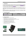
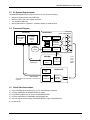
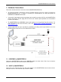
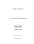
MAXREFDES24EVSYS User Manual Rev 1; 1/15 Windows PC ADCLITE2 ANALOG SIGNAL CAPTURE GUI MAX15500 SIGNAL CONDITIONERS MAXREFDES24 REFDES24 4-CHANNEL ANALOG OUTPUT GUI 20–30VDC (>150mA) MAX1659 LDO MAX6126 VREF MAX5134 4-CHANNEL 16-BIT DAC MAX17498 FLYBACK CONTROL MAX14850 DIGITAL ISOLATOR SPI USB2PMB1 USB CONTROL AND DIAGNOSTICS MAX1556 DC-DC MAX8511 LDO USB MEASUREMENT MAXQ622 CONTROLLER FT2232HL USB CONTROLLER 0–10V 0–5V ±10V 0–20mA ±20mA MAXADCLITE2 MAX11645 2-CHANNEL 12-BIT ADC For pricing, delivery, and ordering information, please contact Maxim Direct at 1-888-629-4642, or visit Maxim Integrated’s website at www.maximintegrated.com. Maxim Integrated cannot assume responsibility for use of any circuitry other than circuitry entirely embodied in a Maxim Integrated product. No circuit patent licenses are implied. Maxim Integrated reserves the right to change the circuitry and specifications without notice at any time. © 2015 Maxim Integrated Products, Inc. Maxim Integrated and the Maxim Integrated logo are trademarks of Maxim Integrated Products, Inc. MAXREFDES24EVSYS User Manual Table of Contents 1 2 3 4 5 6 7 8 Introduction ......................................................................................................................................... 3 1.1 Ordering Information .................................................................................................................. 3 1.2 Package Contents...................................................................................................................... 3 1.3 PC System Requirements ......................................................................................................... 4 1.4 Functional Diagram .................................................................................................................... 4 1.5 Quick Start Instructions .............................................................................................................. 4 Software Description .......................................................................................................................... 5 Hardware Connections ....................................................................................................................... 6 3.1 USB2PMB1 to MAXREFDES24 ................................................................................................ 6 3.2 24VDC to MAXREFDES24 ........................................................................................................ 6 3.3 USB2PMB1 to PC ...................................................................................................................... 7 3.4 MAXADCLITE2 to PC ................................................................................................................ 7 3.5 Analog Signal Connections ........................................................................................................ 8 Graphical User Interfaces ................................................................................................................... 9 4.1 GUI for MAXREFDES24 ............................................................................................................ 9 4.1.1 USB2PMB Adapter .......................................................................................................... 9 4.1.2 MAX15500 Output Conditioners .................................................................................... 11 4.1.3 MAX5134 DAC (Code Generator) ................................................................................. 13 4.2 GUI for MAXADCLITE2 ........................................................................................................... 14 4.2.1 Scope Options ................................................................................................................ 14 Hardware Description ....................................................................................................................... 15 5.1 MAXREFDES24....................................................................................................................... 15 5.2 MAXADCLITE2 ........................................................................................................................ 15 5.3 USB2PMB1 .............................................................................................................................. 15 Contact Information .......................................................................................................................... 16 Trademarks ........................................................................................................................................ 16 Revision History ................................................................................................................................ 17 Rev 1 2 MAXREFDES24EVSYS User Manual 1 Introduction The MAXREFDES24EVSYS design accelerator kit allows users to quickly demonstrate and evaluate the functionality of Maxim Integrated’s 4-channel analog output (AO) reference design (MAXREFDES24) without the need for a bench power supply, digital multimeter, or Xilinx development kit. The reference board connects to a PC through an included USB-to-SPI adapter (USB2PMB1) that provides data communication to the board. A universal power adaptor is included for providing 24V DC power. To exercise the AO reference design, a USB-powered signal capture board (MAXADCLite2) utilizing one of Maxim Integrated’s 12-bit analog-to-digital converters (ADCs) is also included. The simple tool provides two inputs capable of measuring unipolar analog control signals up to 10V (or 20mA with selectable termination resistor). Windows®-based graphical user interfaces (GUIs) communicate with the boards for generating and capturing various signal test patterns. An intuitive alarm interface is also provided for demonstrating the digital diagnostics capabilities of the MAX15500 output conditioners. 1.1 Ordering Information PART MAXREFDES24EVSYS# DESCRIPTION Bundled kit for PC evaluation of MAXREFDES24 #Denotes a RoHS-compliant device that may include lead that is exempt under the RoHS requirements. 1.2 Package Contents The MAXREFDES24EVSYS kit includes the following: • MAXREFDES24 reference design board (Pmod • Universal 24VDC power supply with international plugs and test clip adapter • USB2PMB1 USB-to-Pmod Type 2A adapter board • USB-powered MAXADCLite2 signal capture board TM compatible) • Two (2) USB type-A male to USB type-B mini cables • Two (2) wires with hook clips (1 red and 1 black) • USB flash drive with documentation and GUI applications • Quick Start Guide (print copy) Rev 1 3 MAXREFDES24EVSYS User Manual 1.3 PC System Requirements The MAXREFDES24EVSYS kit requires the use of a PC with the following: • Minimum 1GHz processor and 1GB RAM • Minimum 1024 x 768 video display resolution • Two available USB ports • Microsoft Windows 8, Windows 7, Windows Vista®, or Windows XP® 1.4 Functional Diagram Windows PC ADCLITE2 ANALOG SIGNAL CAPTURE GUI MAXREFDES24 REFDES24 4-CHANNEL ANALOG OUTPUT GUI 20–30VDC (>150mA) MAX1659 LDO MAX15500 SIGNAL CONDITIONERS MAX6126 VREF MAX5134 4-CHANNEL 16-BIT DAC MAX17498 FLYBACK CONTROL MAX14850 DIGITAL ISOLATOR SPI USB2PMB1 USB CONTROL AND DIAGNOSTICS MAX1556 DC-DC MAX8511 LDO USB MEASUREMENT *BIPOLAR MODES NOT COMPATIBLE WITH MAXADCLITE2 HARDWARE. MAXQ622 CONTROLLER FT2232HL USB CONTROLLER 0–10V 0–5V ±10V* 0–20mA ±20mA* MAXADCLITE2 MAX11645 2-CHANNEL 12-BIT ADC 1.5 Quick Start Instructions 1) 2) 3) 4) 5) 6) Copy USB flash drive contents to PC (if only two USB ports available). Connect USB2PMB1 to MAXREFDES24 as shown. Plug 24VDC adapter into AC source and MAXREFDES24. Connect USB cables to USB2PMB1 and MAXADCLite2. Use test clips to connect output of MAXREFDES24 to input of MAXADCLite2. Launch GUIs. Rev 1 4 MAXREFDES24EVSYS User Manual 2 Software Description There are two Windows GUI applications included with MAXREFDES24EVSYS that can be executed directly from the USB flash drive after USB connections have been established with the boards and Windows completes driver installation. See the Graphical User Interfaces section for screenshots and user information. • 4-Channel Analog Output GUI utilizes the USB2PMB1 adapter for exercising the digital interface of the MAXREFDES24 design. This includes the SPI port of the MAX5134 4-channel DAC and multiple MAX15500 output conditioners. This GUI application utilizes the .NET 4.0 platform and does not require installation of any Maxim Integrated software. • MAXADCLite2 GUI for capturing analog test signals with the MAXADCLITE2 board in order to evaluate the performance of the AO reference design. This application does not require installation. If only two (2) USB ports are available, copy the USB flash drive contents directly to your local hard drive or download the USB flash drive contents from www.maximintegrated.com/MAXREFDES24. Rev 1 5 MAXREFDES24EVSYS User Manual 3 Hardware Connections This section describes the basic connections with the MAXREFDES24EVSYS kit. • The user must provide a Windows PC with two available USB ports and an AC outlet for operating the MAXREFDES24EVSYS kit. In addition to providing PC communications, the USB ports power the USB2PMB1 and MAXADCLite2 boards. • A universal AC wall adapter and test clip adapter are included for providing 24V DC to the MAXREFDES24 analog output board. Any DC supply with 20–30V DC and >150mA output capabilities can be substituted for the AC wall adapter. • The MAXREFDES24 and USB2PMB1 boards mate together via a 12-pin Pmod Type 2A connector. For TM more information on the Pmod form factor, refer to the Digilent Pmod Interface Specification or visit www.DigilentInc.com. • A pair of wires with test clips is provided for establishing an analog control signal between one of the MAXREFDES24 outputs and one of the MAXADCLite2 inputs. 3.1 USB2PMB1 to MAXREFDES24 Connect the MAXREFDES24 board to the USB2PMB1 adapter as shown above. Both 12-pin connectors should be on the same side of the PCB when mated together. 3.2 24VDC to MAXREFDES24 Connect the color coded test clips of the DC power adapter to the MAXREFDES24 board as shown above. Red clips connect to +24V and black clips connect to PGND. Rev 1 6 MAXREFDES24EVSYS User Manual 3.3 USB2PMB1 to PC Connect one of the USB cables between the USB2PMB1 board and PC. The USB2PMB1 adapter board includes an FTDI FT2232HL USB controller IC that performs the USB functions and conversion to SPI. Upon attaching the USB2PMB1 adapter board to the PC, the Found New Hardware Wizard automatically launches and installs the appropriate driver files. Multiple drivers will be installed before it is ready to use. To verify proper installation, one should see two USB Serial Converters (A and B) in the Device Manager as shown below. If your PC does not find the FTDI driver files on the local hard disk drive, locate and reference the \USB2PMB1\Drivers\ subdirectory on the USB flash drive to install FTDI’s D2XX driver. 3.4 MAXADCLite2 to PC Connect one of the provided USB cables between the MAXADCLITE2 board and PC. The on-board controller presents itself to the PC as a USB HID class device in the Windows Device Manager as shown below and does not require any third-party drivers. Rev 1 7 MAXREFDES24EVSYS User Manual 3.5 Analog Signal Connections The diagram below shows an example connection between an analog output (OUT1) on MAXREFDES24 and an analog input (AIN0) on MAXADCLITE2 along with the ground connection between the two analog grounds (AGND). All analog grounds are tied together on MAXREFDES24. MAXREFDES24 OUT1 JU2 JU1 JU4 1 2 3 JU6 OUT2 JU3 JU7 JU5 OUT3 1 2 3 JU8 OUT4 MAXADCLITE2 J9 AIN0 AIN1 J4 0 1 GND The jumpers shown above for the MAXREFDES24 select between 5% (default) and 20% overrange modes while the jumpers shown for MAXADCLITE2 select the on-board termination resistor for testing current loops. The following table summarizes the analog output signal ranges for the MAXREFDES24 design along with the required hardware jumper settings. See the Graphical User Interfaces section for all other mode controls. MAX15500 OVERRANGE CONTROL OUTPUT SIGNAL RANGE 0–20mA + 5% ±20mA + 5% 0-20mA + 20% ±20mA + 20% 0–5V + 5% 0–10V + 5% 0–5V + 20% 0–10V + 20% ±10V + 20% -140µA to 21mA -21mA to 21mA -150µA to 24mA -24mA to 24mA -0.28V to 5.36V -0.56V to 10.71V -0.31V to 6.08V -0.63V to 12.16V -12.28V to 12.28V FSMODE (JU1, JU3, JU5, JU7) SENSER (JU2, JU4, JU6, JU8) Jumper 2:3 Don’t Care Jumper 1:2 MAXADCLITE2 AIN TERMINATION (J4, J9) Jumper Closed (500Ω Load) Jumper 1:2 Don’t Care Jumper 2:3 Jumper Open (1kΩ Load) Note the output range of the MAXREFDES24 analog outputs exceeds the input range capabilities of the MAXADCLITE2 board, which only supports unipolar signals up to 10V or 20mA. Signals outside of this range will be clamped by on-board protection diodes. Rev 1 8 MAXREFDES24EVSYS User Manual 4 Graphical User Interfaces Before launching the GUI applications, make sure the USB2PMB1 and MAXADCLITE2 boards are connected to the PC as described in the previous section. 4.1 GUI for MAXREFDES24 With the USB2PMB1 board connected, run (double-click) the 4-Ch_Analog_Output.exe file located in the \MAXREFDES24\ directory of the USB flash drive. Once the GUI window appears, only the USB connectivity section will be active. The other two sections for the analog signal chain components are grayed out until the USB connection is established USB CONNECTIVITY MAX5134 DAC CODE GENERATION 4.1.1 MAX15500 OUTPUT CONDITIONER CONFIGURATION AND STATUS USB2PMB Adapter USB connectivity is managed in the USB Adapter section located in the upper left-hand corner of the application. Click Scan Adapters to discover any compatible USB2PMB devices (starting with PMOD). If no adapters are found, the GUI offers the user the ability to enter into a “Demo GUI” mode where the user can exercise the features of the GUI without communicating to any hardware. Click on Connect once the adapter starting with PMODxxxxxxx appears. Rev 1 9 MAXREFDES24EVSYS User Manual Connection Troubleshooting: If you see this pop-up screen after clicking Scan Adapters, check USB connection to the PC and USB2PMB1 adapter. Also confirm drivers are installed in Windows Device Manager. Click No and try scanning for adapters again. Click Yes to proceed launching the GUI in a demo mode. If you see this pop-up after clicking Connect, make sure the J1 connector of the MAXREFDES24 board is connected to USB2PMB1. Also make sure 24VDC is applied to the MAXREFDES24 board. Rev 1 10 MAXREFDES24EVSYS User Manual 4.1.2 MAX15500 Output Conditioners Following USB connection, the MAX15500 Output Conditioners section will refresh to show the default configuration and initial error states of the MAX1550 devices. Upon any power-up (or supply brownout condition), the Supply Brownout alarm is expected. A red LED on the MAXREFDES24 hardware will also be on. A subsequent Refresh of the MAX15500 Output Conditioners section will clear the alarm. One can set the Brownout threshold in 2V increments from ±10V to ±24V. In the MAXREFDES24 design, a brownout threshold of ±24V triggers a Supply Brownout alarm. The default mode upon power up for the analog outputs is Standby with a ±10V brownout threshold and thermal protection disabled. Use the Configuration sections to configure the on-board MAX15500 signal conditioners to output common industrial control signal ranges (current or voltage) and to read back any error conditions the MAX15500 report. • Use the Refresh button to read and refresh the Configuration and Error(s) status of the MAX15500 devices. • Use the Apply button to write the displayed configuration to the MAX15500 devices. Enable Refresh On Apply to immediately issue a read or Refresh command following a write or Apply. Rev 1 11 MAXREFDES24EVSYS User Manual Common error states and their meaning are summarized below. Refer to the MAX15500 IC data sheet for full details on the error detection capabilities and register behavior. When operating in voltage modes, the Short Circuit error is asserted if the respective output is shorted to analog ground. If the short circuit condition has been resolved, a subsequent Refresh asserts both the Intermittent Fault and Short Circuit errors. A second Refresh clears the error unless the short circuit condition has returned. If the short circuit condition remains, the error remains asserted as shown above. Rev 1 When operating in current modes, the Open Load error is asserted if there is an open circuit in the current loop for the respective output. If the Intermittent Fault error is ever asserted, one or more of the other asserted error conditions has cleared before the user read the status register. If the open load condition has been resolved, a subsequent Refresh asserts both the Intermittent Fault and Open Load errors. A second Refresh clears the error unless the open load condition has returned. A subsequent Refresh clears the intermittent errors and leaves any persistent error alarms asserted. If the open load condition remains, the error remains asserted as shown above. 12 MAXREFDES24EVSYS User Manual 4.1.3 MAX5134 DAC (Code Generator) The MAX5134 DAC control section allows users to send a single DAC value for a DC output or to pick from a few basic waveforms. Signal levels are set in DAC codes (range of 0 to 65535) and are sent to all four DAC outputs. See the table in the Analog Signal Connections section for respective output signal levels. Note that the USB overhead encountered in the USB2PMB1 board (through use of FTDI chipset’s software device driver) will throttle throughput from the PC to the MAX5134 quad-DAC device (when generating waveform signals) to approximately 2.6K DAC sampling points per second. Refer to Reference Schematic 5839: Alameda (MAXREFDES24#): 4-Channel Analog Output for more information on performance results for the DAC and MAXREFDES24 reference design using a Xilinx development kit. Rev 1 13 MAXREFDES24EVSYS User Manual 4.2 GUI for MAXADCLITE2 With the MAXADCLITE2 board connected, run (double-click) the MAXADCLite2.exe file located in the \MAXADCLITE2\ directory. The application runs in a continuous sampling mode at a sampling rate of 1ksps. The only user control is selecting the input channel (default AIN0). The ADCLite2 is basic and simple way to quickly look at the MAXREFDES24 output waveforms. For more information on the MAX11645 and other evaluation kits, go to www.maximintegrated.com/MAX11645. 4.2.1 Scope Options Holding the mouse cursor over the top right corner of the Scope or the Histogram plot displays the plot settings options available to the user, which include play/pause, zoom in/out, pan, print, save, and waveform settings. Rev 1 14 MAXREFDES24EVSYS User Manual 5 Hardware Description This section provides more information on the hardware design of the three boards including schematics, bill of materials, and PCB layout files. 5.1 MAXREFDES24 The MAXREFDES24 reference design is a 4-channel analog output (AO) subsystem that generates controlled voltages or current loop signals using four (4) output conditioners (MAX15500) and a 4-channel 16-bit DAC (MAX5134). For maximum performance, an ultra-high precision 4.096V voltage reference (MAX6126) is included. A 600VRMS digital isolator (MAX14850), power transformer, and flyback controller (MAX17498) provide the necessary isolated data and power connections to the analog sub-system. Reference Schematic 5839: Alameda (MAXREFDES24#): 4-Channel Analog Output provides more information on the MAXREFDES24 design and includes performance test results of the reference design when used with a Xilinx development system. Refer to this online document for links to the latest hardware design files, test results, relevant application notes, and project files for select Xilinx development kits. Below is a summary of the hardware design files available on the USB flash drive for the MAXREFDES24 design. Bill of Materials PCB Source Files Schematics (PDF) Layout (PDF) Layout (Gerber) USB Flash Drive 5.2 MAXADCLITE2 The MAXADCLite2 board utilizes a low-power, 2-channel, 12-bit ADC (MAX11645) with an input circuit that offers basic input protection, selectable current loop termination (jumpers J4, J9), and a divide-by-5 resistor ladder for scaling analog signals (up to 10V) to levels compatible with the ADC’s 2.048V internal reference. A 2 microcontroller (MAXQ622) provides bridge functionality between a USB HID interface and I C-compatible bus. The described limitations are reflected by the suffix “Lite” in the name of the board. For more information on the MAX11645 and full evaluation kits, go to www.maximintegrated.com/MAX11645. . 5.3 USB2PMB1 The USB2PMB1 board uses the FT2232HL, a USB 2.0 high-speed (480Mbps) to UART/FIFO IC, to process commands sent by a GUI application running on the PC. The design integrates a 4K MICROWIRE®compatible serial EEPROM (93LC66BT) and a low-power, 1.2A, PWM step-down DC-DC converter (MAX1556) for generating 3.3V (VCCIO) from the 5V USB supply. VCCIO provides power to the FTDI chip, the 4K MICROWIRE EEPROM, and to the 12-pin connector for 3.3V Pmod Type 2A-compatible boards. For more information on the USB2PMB1 hardware design or other compatible boards from Maxim Integrated, go to www.maximintegrated.com/USB2PMB1. For more information on the Pmod form factor, refer to the TM Digilent Pmod Interface Specification or visit www.DigilentInc.com. Rev 1 15 MAXREFDES24EVSYS User Manual 6 Contact Information For more information about Maxim Integrated products, contact technical support at www.maximintegrated.com/support. 7 Trademarks MICROWIRE is a registered trademark of National Semiconductor Corp. Pmod is a trademark Digilent Inc. Windows is a registered trademark and registered service mark and Windows Vista and Windows XP are registered trademarks of Microsoft Corporation. Rev 1 16 MAXSANTAFEEVSYS User Manual 8 Revision History PAGES CHANGED REVISION NUMBER REVISION DATE 0 11/14 Initial release — 1 1/15 Corrected the required hardware jumpers for FSMODE in the table of Section 3.5 Analog Signal Connections 8 Rev 1 DESCRIPTION 17