1
842D DeviceNet
Encoder
Catalog Numbers:
842D-60131331BDA and
842D-60131331BXA Revision 4.001
User Manual
Important User Information
Because of the variety of uses for the products described in this
publication, those responsible for the application and use of this
control equipment must satisfy themselves that all necessary steps
have been taken to assure that each application and use meets all
performance and safety requirements, including any applicable laws,
regulations, codes and standards.
The illustrations, charts, sample programs and layout examples
shown in this guide are intended solely for purposes of example.
Since there are many variables and requirements associated with any
particular installation, Rockwell Automation does not assume
responsibility or liability (to include intellectual property liability) for
actual use based upon the examples shown in this publication.
Rockwell Automation publication SGI-1.1, Safety Guidelines for the
Application, Installation, and Maintenance of Solid-State Control
(available from your local Rockwell Automation office), describes
some important differences between solid-state equipment and
electromechanical devices that should be taken into consideration
when applying products such as those described in this publication.
Reproduction of the contents of this copyrighted publication, in
whole or in part, without written permission of Rockwell
Automation, is prohibited.
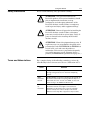
Throughout this manual we use notes to make you aware of safety
considerations:
!
ATTENTION: Identifies information about practices
or circumstances that can lead to personal injury or
death, property damage or economic loss.
Attention statements help you to:
•
Identify a hazard.
•
Avoid the hazard.
•
Recognize the consequences.
Important: Identifies information that is critical for successful
application and understanding of the product.
Table of Contents
Preface
Using this Manual
Objectives .............................................................................P-1
Who Should Use this Manual?..............................................P-1
Purpose of this Manual .........................................................P-1
Contents of this Manual ........................................................P-2
Related Publications .............................................................P-2
Safety Precautions ............................................................... P-3
Terms and Abbreviations ......................................................P-3
Conventions Used in this Manual..........................................P-5
Rockwell Automation Support ...............................................P-5
Local Product Support ..........................................................P-5
Technical Product Support ....................................................P-5
Chapter 1
Overview
Chapter Objectives ............................................................... 1-1
Overview of the Encoder....................................................... 1-1
Features of the Encoder........................................................ 1-1
Overview of Setting Up the Encoder ..................................... 1-2
Chapter 2
Installation
Chapter Objectives ............................................................... 2-1
Installing a Bulletin 842D DeviceNet Encoder....................... 2-1
Selecting Cables ................................................................... 2-1
Installing the DeviceNet Encoder .......................................... 2-2
Chapter 3
Configuring the DeviceNet Encoder DIP Switches
Chapter Objectives ............................................................... 3-1
Setting up the 842D DeviceNet Encoder .............................. 3-1
Setting the Node Address ..................................................... 3-2
Setting the baud rate............................................................. 3-2
Diagnostic LED ..................................................................... 3-2
Bus termination ..................................................................... 3-3
Preset function ...................................................................... 3-3
ii
Chapter 4
Configuring the Encoder Using RSNetworx for DeviceNet
Chapter Objectives ........................................................................... 4-1
What is RSNetWorx for DeviceNet? ................................................. 4-1
Required Equipment and Software ................................................... 4-1
Going Online..................................................................................... 4-2
Installation of the EDS File ............................................................... 4-4
Offline Integration into the Network .................................................. 4-4
Accessing and Editing Parameters ................................................... 4-5
Enhanced Device Configuration in Offline Mode .............................. 4-6
Enhanced Device Configuration in Online Mode .............................. 4-7
Saving Parameter Values to EEPROM ............................................. 4-7
Restoring Parameters to EEPROM Values....................................... 4-7
Setting Parameters to Default Values ............................................... 4-7
Chapter 5
Configuring a Scanner to Communicate with the Encoder
Chapter Objectives ........................................................................... 5-1
Required Equipment and Software ................................................... 5-1
Operating Modes of the Encoder...................................................... 5-1
Example DeviceNet Network ............................................................ 5-4
Setting Up the Scan List ................................................................... 5-4
Mapping the Product’s Data in the Scanner ..................................... 5-7
Saving the Configuration .................................................................. 5-8
Chapter 6
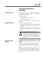
Using DeviceNet Explicit Messaging
Chapter Objectives .......................................................................... 6-1
Required Equipment ........................................................................ 6-1
Explicit Messaging Preset Example for the 1747-SDN Scanner ...... 6-1
Explicit Messaging Prest Example for the 1756-DNB....................... 6-6
Appendix A
842D Specifications and Dimensions ................................. A-1
Appendix B
DeviceNet Objects
Appendix Objectives .........................................................................B-1
Object Classes..................................................................................B-1
Class Code 01hex — Identity Object ................................................B-1
Class Code 02hex — Message Router.............................................B-2
Class Code 03hex — DeviceNet ......................................................B-2
Class Code 04hex — Assembly .......................................................B-3
Class Code 05hex — Connection.....................................................B-4
Class Code 2Fhex — Encoder .........................................................B-7
Designation of Alarm Bits ...............................................................B-10
Designation of Warning Bits ...........................................................B-10
Designation of Cam Bits .................................................................B-10
Preface
Using this Manual
Objectives
Who Should Use this
Manual?
Read this preface to become familiar with the organization of the
manual. In this preface, you will read about the following:
•
Who should use this manual.
•
An overview of the 842D DeviceNetTM absolute rotary shaft
encoder.
•
The purpose of this manual.
•
Terms and abbreviations.
•
Conventions used in this manual.
•
Rockwell Automation support.
Use this manual if you are responsible for installing, wiring,
programming, or troubleshooting control systems that use the 842D
encoder.
This manual is intended for qualified service personnel responsible
for setting up and servicing the 842D encoder. You must have
previous experience with and a basic understanding of electrical
terminology, programming procedures, networking, required
equipment and software, and safety precautions.
Purpose of this Manual
This manual is a learning and reference guide for the 842D encoder. It
describes the procedures needed to install, configure, and
troubleshoot the encoder.
P-2
Using this Manual
Contents of this Manual
This manual contains the following information:
Chapter
Preface
Title
Contents
Using this Manual
Describes the purpose, background and scope of this manual. Also provides
information on safety precautions and technical support.
1
Overview
Provides an overview of the 842D Encoder.
2
Installation
Provides a procedure for installing the 842D encoder.
3
Configuring the DeviceNet
Encoder DIP Switches
Describes the setting of node address, bus termination, baud rate and
PRESET function.
4
Configuring the Encoder
Using RSNetWorx for
DeviceNet
Provides information that you need to configure the encoder (online and
offline) over the DeviceNet network.
5
Configuring a Scanner to
Communicate with the
Encoder
Provides instructions for configuring a PLC or SLC scanner to communicate
with the encoder.
6
Using DeviceNet Explicit
Messaging
Includes information you need to monitor and configure the encoder using
explicit messaging on DeviceNet. Features an example of explicit messaging.
A
Specifications and
Dimensions
Provides the specifications and physical dimensions of the 842D encoder.
B
DeviceNet Objects
Defines the DeviceNet object classes, class services, and attributes that are
supported by the DeviceNet encoder.
Related Publications
Title
Publication Number
RSNetWorx for DeviceNet Getting Results
Manual
9398-DNETGR
1747-SDN DeviceNet Scanner Configuration
Manual
1747-6.5.2
1747-SDN DeviceNet Scanner Module Manual
1747-5.8
DeviceNet Media, Sensors and Distributed I/O
1485-CG001A-EN-P
DeviceNet Cable System Planning and
Installation Manual
DN-6.7.2
RSLogix 5 Getting Results Guide
9399-RL53GR
RSLogix 500 Getting Results Guide
9399-RL50GR
RSLogix 5000 Getting Results Guide
9399-RLD300GR
Using this Manual
Safety Precautions
Please read the following safety precautions carefully.
!
!
!
Terms and Abbreviations
P-3
ATTENTION: Only personnel familiar with
DeviceNet products and associated machinery should
plan or implement the installation, start-up,
configuration, and subsequent maintenance of the
DeviceNet absolute encoder. Failure to comply may
result in personal injury and/or equipment damage.
ATTENTION: Remove all power before installing the
DeviceNet absolute encoder. Failure to disconnect
power may result in death or serious injury. Verify all
power is removed before installing the DeviceNet
absolute encoder.
ATTENTION: Hazard of equipment damage exists. If
explicit messages are programmed to frequently write
parameter data to the 842D EEPROM, the EEPROM can
exceed its life cycle and cause the product to
malfunction. Do not create a program that frequently
uses explicit messages to write parameter data to a
product. (See EEPROM Life specification on page A-1.)
For a complete listing of Allen-Bradley terminology, refer to the
Allen-Bradley Industrial Automation Glossary, Publication AG-7.1.
Terms
Definition
DeviceNet
An open network that provides probabilistic I/O control
through a managed bit-wise non-destructive multiplexing
scheme.
842D
DeviceNet
Encoder
An Allen-Bradley encoder that communicates directly with the
DeviceNet network without requiring additional adapters. In
this manual, the terms “encoder” and “842D” are also used
when referring to the 842D DeviceNet Encoder.
RSNetWorx
for
DeviceNet
A Rockwell Software application that can be used to set up
DeviceNet networks and configure connected devices.
RSNetWorx for DeviceNet (version 3.00.00) and RSLinx
(version 2.20.02) were used for examples in the manual.
Different versions may differ in appearance and procedures.
P-4
Using this Manual
Abbreviation
Full Name
Definition
CAN
Controller Area Network
Physical layer definition
ODVA
Open DeviceNet Vendor Association
User organization for DeviceNet.
ID
Identifier
EDS
Electronic Data Sheet
ScF
Scaling factor
Measuring units per revolution / Single turn
resolution
Pos_calc
calculated position value
calculated current position value, after clearing
with Offset, ScF, Preset
Pos_num
numerical position value
numerical (physical) position value before
clearing with Offset, ScF, Preset
BOOL
Boolean
Bit
BYTE
Bit String
1 Byte (8 Bit)
WORD
Bit String
2 Byte (16 Bit)
USINT
Unsigned Short Integer
Int (1 Byte) - (0...255)
UINT
Unsigned Integer
Int (2 Byte) - (0...65,535)
UDINT
Unsigned Double Integer
Int (4 Byte) - (0...+232 -1)
SINT
Signed Short Integer
Int (1 Byte) - (-128...+127)
INT
Signed Integer
Int (2 Byte) - (-32,768...+32,767)
DINT
Signed Double Integer
Int (4 Byte) - (-231...+231 - 1)
LSB
Least Significant Bit / Byte
MSB
Most Significant Bit / Byte
Data Types
Using this Manual
Conventions Used in this
Manual
P-5
The following conventions are used throughout this manual:
•
Bulleted lists provide information, not procedural steps.
•
Numbered lists provide sequential steps or hierarchical
information.
•
Italic type is used for chapter names and for parameter names.
•
Bold type is used for names of menus, menu options, screens, and
dialog boxes.
Important: This type of paragraph contains tips or notes that have
been added to call attention to useful information.
Rockwell Automation
Support
Rockwell Automation offers support services worldwide, with more
than 75 sales/support offices, more than 500 authorized distributors,
and more than 250 authorized systems integrators located throughout
the United States alone. In addition, Rockwell Automation
representatives are in every major country in the world.
Local Product Support
Contact your local Rockwell Automation representative for:
•
Sales and order support.
•
Product technical training.
•
Warranty support.
•
Support service agreements.
Technical Product Support
If you need to contact Rockwell Automation for technical assistance,
please call your local Rockwell Automation representative.
Refer to http://www.ab.com for updates and supporting
documentation.
P-6
Notes:
Using this Manual
Chapter
1
Overview
Chapter Objectives
Chapter 1 provides an overview of your 842D DeviceNet absolute
encoder. In this chapter, you will read about the following:
•
Function of the 842D encoder.
•
Features of the 842D encoder.
•
Steps for setting up the encoder.
•
Required tools and equipment.
Overview of the Encoder
The 842D absolute multi-turn encoder provides a total resolution of
26 bits. The single-turn position value is transmitted with 13 bits. The
number of multi-turn revolutions is 13 bits. Revolutions are counted
by the use of a gear mechanism. The bus interface is located in the
encoder and is configured as a DeviceNet slave according to
DeviceNet specification, release 2.0.
Features of the Encoder
The DeviceNet network is an open, global industry-standard
communication network designed to provide an interface through a
single cable from a programmable controller directly to “smart”
devices such as sensors, push buttons, motor starters, operator
interfaces and drives.
The 842D DeviceNet encoder connects directly to the a DeviceNet
network without the need for additional adapters. Features of the
842D include:
•
26-bit absolute multi-turn operation (8192 steps per revolution x
8192 revolutions) without batteries
•
Supports Polling, Cyclic, Change of State (COS) and Bit Strobed
I/O messaging
•
Transmission rate up to 500 kBaud.
•
Programmable functions
–
Electronic alignment (PRESET or Number-SET). Electronic
alignment may be carried out via DeviceNet or via a pushbutton in the bus connector of the 842D.
–
Clockwise or Counterclockwise (CW/CCW) counting
direction
1-2
Overview
Overview of Setting Up the
Encoder
–
Scaling function - Setting the single-turn resolution as well as
the number of turns. The single-turn resolution is any whole
number from 1 to 8192. The number of turns must be 1, 2, 4,
8, 16, 32, 64... up to 8192.
–
Up to eight programmable cams
–
Velocity Warning Flags
•
Status information is available via the Network Status LED on
the back of the encoder.
•
Velocity Feedback (Steps per second, RPM, or RPS)
•
Diagnostic and Position Error Alarms
•
Node address, Baud rate, and bus termination resistance are
selected via DIP switches under the removable cover on the back
of the encoder.
To set up the 842D DeviceNet encoder, you must perform the
following tasks:
1. Install the encoder. Refer to Chapter 2, Installation.
2. Set the encoder’s node address, transmission rate and bus
termination. Refer to Chapter 3, Configuring the DeviceNet
Encoder DIP Switches.
3. Configure the encoder’s parameters. Refer to Chapter 4,
Configuring the Encoder Using RSNetWorx for DeviceNet.
4. Configure a scanner (either PLC or SLC) to communicate with
the encoder. Refer to Chapter 5, Configuring a Scanner to
Communicate with the Encoder.
Chapter
2
Installation
Chapter Objectives
Installing a Bulletin 842D
DeviceNet Encoder
Chapter 2 provides the information that you need to install the 842D
DeviceNet encoder. In this chapter, you will read about the following:
•
Cable connections.
•
Installing the encoder.
Selecting Cables
To connect the encoder to the DeviceNet network, you must select an
appropriate DeviceNet drop cable. A drop line connects a node, such
as an encoder, to the DeviceNet trunk cable. Use the following
information to select appropriate cables for each connection.
Bulletin 842D DeviceNet encoders are available with a single 5-pin
micro quick disconnect or two 5-pin quick disconnects (one male and
one female) for ‘daisy chain’ connections.
Catalog Number
Electrical Connection
842D-60131331BDA
One 5-pin male micro QD
842D-60131331BXA
Two 5-pin micro QDs (one male & one female)
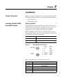
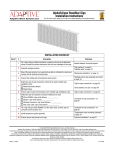
Pin configurations are per the DeviceNet specification as follows:
Figure 2.1
DeviceNet Micro Connections
Female Micro
3
5
2
Male Micro
4
1
4
1
5
3
2
1
Drain
Bare
2
V+
Red
3
V-
Black
4
CAN_H
White
5
CAN_L
Blue
Refer to the table below for recommended drop cables. .
Length
Right Angle Micro Male to Straight Micro Female
1m
1485R-P1R5-F5
2m
1485R-P2R5-F5
3m
1485R-P3R5-F5
4m
1485R-P4R5-F5
5m
1485R-P5R5-F5
6m
1485R-P6R5-F5
2-2
Installation
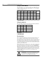
It is also important to determine the limitations of the trunk and drop
cables. Refer to the following table.
Data Rates
125 Kbps
250 Kbps
500 Kbps
Thick Trunk Line
500 m (1,640 ft)
250 m (820 ft)
100 m (328 ft)
Thin Trunk Line
100 m (328 ft)
100 m (328 ft)
100 m (328 ft)
Maximum Drop Length
6 m (20 ft)
6 m (20 ft)
6 m (20 ft)
Cumulative Drop Budget
156 m (512 ft)
78 m (256 ft)
39 m (128 ft)
For more information on DeviceNet cables and cable systems, refer to
the DeviceNet Cable System Planning and Installation Manual,
Publication DN-6.7.2.
Installing the DeviceNet Encoder
The following instructions explain how to physically install your
DeviceNet encoder.
1. Be sure to select the proper size flexible coupling clamp to mate
to the encoder shaft, e.g., 845-FC-*-*. See the Encoder
Accessories section in the Allen-Bradley Sensors catalog.
!
ATTENTION: Only personnel familiar with
DeviceNet products and associated machinery should
plan or implement the installation, start-up,
configuration, and subsequent maintenance of the
DeviceNet absolute encoder. Failure to comply may
result in personal injury and/or equipment damage.
2. Use the dimension drawings to determine the encoder mounting
hole locations. See Appendix A.
3. Slide the flexible coupling onto the shaft, but do not tighten the
set screws.
4. Mount the encoder and tighten with three size M4 mounting
screws (not supplied).
5. Center the flexible coupling and tighten the set screws.
6. Rotate the machine slowly and verify that the flexible coupling is
not deforming beyond specifications.
Chapter
3
Configuring the DeviceNet Encoder
DIP Switches
Chapter Objectives
Setting up the 842D
DeviceNet Encoder
Chapter 3 provides information that you need to configure the
encoder. In this chapter, you will read about the following:
•
Setting the node address.
•
Setting the transmission baud rate
•
Activating bus termination.
•
Diagnostic LED
•
The Preset function.
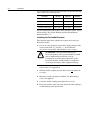
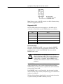
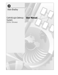
Specific features of the 842D must be configured by means of
hardware settings. (Remote setting of the DIP switches via a Node
Commissioning Tool is not supported at this time.) These features are
Node Address, Baud Rate and the DeviceNet bus termination. In
addition, the encoder can be set to a fixed position value (PRESET
function) by actuating a push-button. In order to execute this
function, the large PG plug on the rear of the encoder has to be
removed. Inside, three DIP switches and a micro push-button become
visible.
Figure 3.1
Encoder DIP Switches
Preset Position
Button
Baud Rate
Node Address
(MAC-ID)
Bus Termination
3-2
Configuring the DeviceNet Encoder DIP Switches
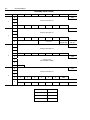
Setting the Node Address
The Node Address is set via the 6-pole DIP switch. The DIP switch
settings are binary starting with switch number 1 = (20) and ending
with switch number 6 (= 25).
DIP-1
DIP-2
DIP-3
DIP-4
DIP-5
DIP-6
20
21
22
23
24
25
0
0
0
0
0
0
0
1
0
0
0
0
0
1
...
...
...
...
...
...
...
1
1
1
1
1
1
63
Address
0 = DIP switch is OFF
1 = DIP switch is ON
Setting the baud rate
The 3-pole DIP switch allows for setting the transmission baud rate.
DIP-1
DIP-2
DIP-3
Baud rate
0
0
X
125 kBaud
1
0
X
250 kBaud
0
1
X
500 kBaud
1
1
X
125 kBaud
X = don't care
0 = DIP switch is OFF
1 = DIP switch is ON
Bus termination
The recommended method for connecting DeviceNet products is to
run a “trunk line” with 120-ohm resistors connected at each end.
DeviceNet products are then connected as “drops” along the length of
the trunk line. In this configuration, the internal termination resistor
of the 842D should not be used and the bus termination DIP switches
should be in the OFF position.
When 842D encoders are connected in a “daisy chain” configuration,
the internal termination resistor may be used on the end positions
only. In this configuration, only 842D(s) at either end of the network
should have their bus termination 2-pole DIP switches placed in the
ON position. Further details on termination resistors can be found in
publication DN-6.7.2 DeviceNet Cable System Planning and
Installation Manual.
!
ATTENTION: If you do not use terminating resistors
as described here and in publication DN-6.7.2, the
DeviceNet system will not operate properly.
Configuring the DeviceNet Encoder DIP Switches
Figure 3.2
3-3
Bus Termination Switches
ON
1
2
Bus Termination
1 and 2 OFF: not active
1 and 2 ON: active
Note: Remote setting of the DIP switches via a Node Commissioning
Tool is not supported at this time.
Diagnostic LED
Once the DIP switches have been properly set, the 842D may be
connected to a DeviceNet network. LED functions are as follows:
LED
Status
Off
Not connected, not on line
Green Blinking
Active but not allocated by master
Green Steady
Active and allocated by master
Red Blinking
Minor fault and/or connection interrupt
Red Steady
Critical communication fault
Preset function
The 842D ‘POSITION VALUE’ is set to zero when the PRESET
function is executed (by Reset Position Button or DeviceNet). This
predefined value is stored in the EEPROM. The factory default
PRESET value is zero.
!
ATTENTION: The PRESET function results in a
change of position reading. This can cause unexpected
motion which could result in personal injury and damage
to the product or equipment. During PRESET, steps
should be taken to ensure the shaft is stationary and will
remain so.
The PRESET function is not intended for use in dynamic parameter
setting operations but as an electronic adjustment function during
commissioning, in order to allocate a specific value to the mechanical
rotary position of the 842D.
If the PRESET value is set by DeviceNet, the value must be within
the total working range currently configured (steps per revolution and
number of revolutions).
The Reset Position Button should only be operated when the encoder
is powered and the green LED is blinking or steady.
3-4
Notes:
Configuring the DeviceNet Encoder DIP Switches
Chapter
4
Configuring the Encoder Using
RSNetWorx for DeviceNet
Chapter Objectives
What is RSNetWorx for
DeviceNet?
Chapter 4 provides information that you need to configure the
encoder over the DeviceNet network. In this chapter, you will read
about the following:
•
RSNetWorx for DeviceNet software and the equipment required
to use it.
•
Going online.
•
Installing the Electronic Data Sheet (EDS) file.
•
Online and offline configuration of the 842D encoder.
•
Accessing, editing and saving encoder parameters.
RSNetWorx for DeviceNet is a Rockwell Software application that
can be used to set up DeviceNet networks and configure connected
devices. RSNetWorx for DeviceNet (version 3.00.00) and RSLinx
(version 2.20.02) were used for examples in the manual. Different
versions may differ in appearance and procedures.
RSNetWorx supports online and offline commissioning of a
DeviceNet system.
During offline commissioning, the bus network is configured and
parameters for the bus participants are set without an established
connection to the bus network. Thereafter the bus connection is made
and the user data are transferred to the master as well as to the bus
participants.
In the online commissioning the bus structure and the parameters of
the participants are configured using an established bus connection.
After installing or mounting the encoder, you can use RSNetWorx for
DeviceNet to configure or edit the encoder’s parameters.
Required Equipment and
Software
Before configuring the encoder and editing its parameters, your PC
must be:
•
Running RSNetWorx for DeviceNet. Refer to
http://www.software.rockwell.com for more information on this
product.
•
Connected to and communicating with the DeviceNet network
using a DeviceNet interface such as a 1784-PCD card or a
1770-KFD adapter.
4-2
Configuring the Encoder Using RSNetWorx for DeviceNet
Going Online
To use RSNetWorx for DeviceNet, you must first set up a driver in
RSLinx. The driver provides a communications link between the
computer and DeviceNet network. Then, you can view the devices on
a DeviceNet network by going online. A device may appear as an
unrecognized device if RSNetWorx for DeviceNet does not have an
EDS file for it.
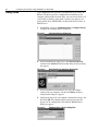
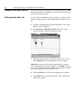
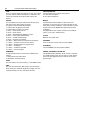
1. Start RSLinx, and select Communications > Configure Drivers
to display the Configure Drivers dialog box.
Figure 4.1
Configure Drivers Dialog Box
2. In the Available Driver Types box, select DeviceNet Drivers,
and then click Add New. The DeviceNet Driver Selection dialog
box appears.
Figure 4.2
DeviceNet Driver Selection Dialog Box
3. In the Available DeviceNet Drivers list, select the adapter
connected to your computer, and then click Select. A Driver
Configuration dialog box appears.
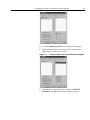
4. Configure the driver for your computer and network settings, and
then click OK. The Configure Drivers dialog box reports the
progress of the configuration. The Add New RSLinx Driver
dialog box appears.
Figure 4.3
Add New RSLinx Driver Dialog Box
Configuring the Encoder Using RSNetWorx for DeviceNet
4-3
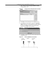
5. Type a name (if desired), and then click OK. The Configure
Drivers dialog box reappears, and the new driver is in the
Configured Drivers List
Figure 4.4
Driver
Configure Drivers Dialog Box with a DeviceNet
6. Click Close to close the dialog box. Leave RSLinx running.
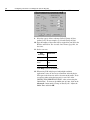
7. Start RSNetWorx for DeviceNet, and then select Network >
Online. If the Browse for Network dialog box appears, RSLinx
has drivers for multiple networks. Select your DeviceNet
network, and click OK. A message appears.
Figure 4.5
DeviceNet Configuration Services Message
8. Click OK to go online. The devices in the network appear in the
Configuration view.
Figure 4.6
Online in RSNetWorx for DeviceNet
4-4
Configuring the Encoder Using RSNetWorx for DeviceNet
Installation of the EDS File
The Electronic Data Sheet, or EDS file, must be installed with
RSNetWorx. The EDS file may be downloaded from our website at
http//www.ab.com/networks/eds/. Simply select DeviceNet followed
by RA Miscellaneous and then press the Search button. By selecting
the 842D encoder, you can begin downloading the 842D EDS file.
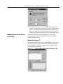
1. Go to Tools - EDS Wizard and click Next to start the process.
Figure 4.7
EDS Wizard
2. Follow the prompts to install the 842D EDS file.
3. Click Finish to complete the process.
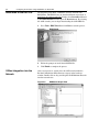
Offline Integration into the
Network
After a new project is started select the 842D encoder under the
Rockwell Automation Miscellaneous category in the hardware
window. Double-click or drag and drop the 842D Multiturn Encoder
into the network view.
Figure 4.8
RSNetworx Graph View
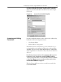
Configuring the Encoder Using RSNetWorx for DeviceNet
4-5
To assign a name, description and node address, double-click on the
encoder in the Graph view window. In the General tab of the Edit
dialog box, enter the node address that has been set via the six pole
DIP switch.
Figure 4.9
Accessing and Editing
Parameters
General Tab in the Edit Dialog Box
In order to modify the parameter values of the encoder on DeviceNet,
RSNetWorx offers two configuration modes:
•
Class Instance Editor
•
Enhanced Device Configuration
The Enhanced Device Configuration is a more comfortable way to
read and modify encoder parameters. This mode can be used online
and offline (file access only). In the Enhanced Device Configuration
mode the parameters can be stored to a file (*.dnt) for later transfer to
the device.
In order to protect parameter values against loss due to a power
failure they can be stored in the encoder EEPROM with the
"Save" service. The "Reset" service sets all parameters to default
values. The "Restore" service sets all parameters to the values
stored in the EEPROM--see page 4-7.
The Save, Reset, and Restore services can only be executed in the
Class Instance Editor.
4-6
Configuring the Encoder Using RSNetWorx for DeviceNet
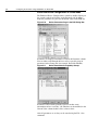
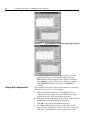
Enhanced Device Configuration in Offline Mode
The Enhanced Device Configuration is started by double-clicking on
the encoder symbol and clicking on the Parameter tab. In offline
mode the parameters are preset to the default values in the EDS file.
Figure 4.10
Device Parameters Page in the Edit Dialog Box
Parameters are displayed in numerical order in the Parameter column.
You can either scroll through the list or select a specific group of
parameters in the Groups box (for example, DeviceNet Module).
Figure 4.11
Device Parameters Arranged by Groups
Parameters labeled with a padlock represent encoder status
information and are ‘read-only’. All other data can be modified; in the
Current Value column, double-click a value to edit it.
After all parameters are set they can be stored using the File - Save
command.
Configuring the Encoder Using RSNetWorx for DeviceNet
4-7
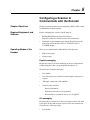
Enhanced Device Configuration in Online Mode
The Enhanced Device Configuration is selected by double-clicking
on the encoder symbol. In on-line mode the parameter values
currently stored in the encoder are accessed.
By clicking on the Apply or Download to Device buttons, the
parameters can be saved to the encoder. The updated encoder values
are stored in the encoder RAM and are valid immediately. Saving the
new values to the EEPROM is done with a separate command.
Saving Parameter Values to
EEPROM
Saving the parameter values to the EEPROM is performed in the
Class Instance Editor.
To access the Class Instance Editor, select the device in the graph
window and click on Class Instance Editor in the Device menu. Select
the service Save (16hex) of Class 2Fhex (encoder object), Instance 1,
with the ‘Send the attribute ID’ box unchecked.
Finish by clicking on the Execute button.
Figure 4.12
Restoring Parameters to
EEPROM Values
Class Instance Editor
In order to set the parameters to the EEPROM values, the service
Restore (15hex) of the encoder object is used.
This is done in the Class Instance Editor . Select the service Restore
(15hex) of the object 2Fhex (encoder object), Instance 1, with the
‘Send the attribute ID’ box unchecked. Finish by clicking on the
Execute button..
!
ATTENTION: The Restore function results in a
change of position reading. This can cause unexpected
motion which could result in personal injury and damage
to the product or equipment. During Resore, steps should
be taken to ensure the shaft is stationary and will remain
so.
4-8
Configuring the Encoder Using RSNetWorx for DeviceNet
Setting Parameters to
Default Values
In order to reset the parameters to the factory default values, the
service Reset (05hex) of the encoder object is used. This is done in the
Class Instance Editor. Select the service Reset (05hex) of the object
2Fhex (encoder object), Instance 1, with the ‘Send the attribute ID’
box unchecked. Finish by clicking on the Execute button.
Chapter
5
Configuring a Scanner to
Communicate with the Encoder
Chapter Objectives
Chapter 5 provides instructions for configuring a PLC or SLC scanner
to communicate with the encoder.
Required Equipment and
Software
Before configuring the scanner, your PC must be:
Operating Modes of the
Encoder
•
Running RSNetWorx for DeviceNet. Refer to
http://www.software.rockwell.com for more information.
•
Connected to and communicating with the DeviceNet network
using a DeviceNet interface such as a 1784-PCD card or a
1770-KFD adapter.
There are two fundamentally different DeviceNet protocols:
•
Explicit messaging
•
I/O messaging
Explicit messaging
Explicit messaging is used for modifying the device configurations,
reading diagnostic values, program upload / download, etc.
Characteristics of explicit messaging:
•
Very flexible
•
Less efficient because each device must interpret and generate a
response
•
"Unbound" connections ("Hit and Run")
•
Contents of the data field:
–
Protocol information
–
Instructions for service to be performed
–
Internal address to which the service is to be applied
I/O messaging
I/O messaging is used for fast or time-critical data transfer. All of the
8 data bytes of the CAN telegram can be used for data transmission.
Characteristics of I/O messaging:
•
Less flexible
5-2
Configuring a Scanner to Communicate with the Encoder
•
Highly efficient for both bandwidth and node processing
•
"Bound" connections
•
Data field contains data only
•
Meaning of data is predefined
Input data specification of the 842D
The 842D encoder is an Input Device. This means the encoder only
produces (sends) data and does not consume any data from the
master.
The 842D supports the following I/O operating modes (message
connections):
•
Polling
•
Change of State (COS) / Cyclic
•
Bit Strobed mode
All these modes can be adjusted simultaneously with different
assembly instances. To use a particular Assembly, there are installed 3
special attributes "assembly number" (Input Ass_xx) in the
manufacturer section of the encoder object. These attributes have to
be configured with the number (1...n) of the corresponding assembly
instance, containing the different data components. By default this
number is set to 1 ("Position Value").
Each of the 3 different I/O message connections is assigned its own
attribute.
The table below shows how the different data components are used:
Data Component
Assembly
Supported
modes
Update cycle
time
Position Value
1, 2, 3, 4
COS, Strobe,
Poll
0.3 ms
Velocity Value
3
Strobe, Poll
50 ms
Flag (Alarm,
Warning)
2
COS, Strobe,
Poll
0.3 ms
Cam State
4
COS, Strobe,
Poll
0.3 ms
Update cycle time is the time required for the encoder to calculate a
new value for one of the listed data components. For example, the
encoder is able to send new position values in intervals of approx.
0.3ms.
Note: For all the different I/O messages applied, the number of the
configured assembly instance determines the data components to be
sent as an input data.
Configuring a Scanner to Communicate with the Encoder
5-3
For more detail see the Assembly object manufacturer specific
functions in Appendix B.
Polling mode
The standard mode in the master-slave communication is the polling
mode. In this mode the master contacts all bus participants cyclically.
The output data are transmitted to the slaves and the input data are
read from the slaves over the course of one scan.
Because the 842D is an Input Device, output data from the master is
ignored. The Poll Command is used to trigger the transmission of
return input data in the response message.
COS mode / Cyclic mode
In Change of State (COS) mode, the encoder sends input data if the
value of one of the data components changes or at the Heartbeat Rate
(See Figure 5.4, Edit I/O Parameters Dialog Box - COS).
In addition, a Cycle Time is used to trigger the transmission of the
input data. This is done after the internal Cycle Time period has
elapsed, no matter if the value of one of the data components has
changed.
Additionally, a time delay (inhibit time) in the range of 1 msec. to
65,535 msec. can be configured to reduce the bus load.
When getting a trigger only from the "cam state" or "Flag" data
components by using Instance 2 or 4 in a COS connection, you should
set the value of "COS / Hyst." (attr. 11) to "0" (zero) to avoid a trigger
from the data component "position value" (see Appendix B).
In Cyclic mode the encoder only sends input data after the internal
Cycle Time period has elapsed.
Bit Strobed mode
The Bit_Strobe Command sends one bit of output data to each Slave
whose node address appears in the Master's scan list.
Because the 842D encoder is an Input Device, the output data bit is
ignored. The Bit Strobe Command is only used to trigger a
transmission of return input data in the response message.
5-4
Configuring a Scanner to Communicate with the Encoder
Example DeviceNet Network
This section provides the steps that are needed to configure a simple
network that includes 1756-DNB/A scanner (Node 10) and an 842D
DeviceNet encoder (Node 03).
Setting Up the Scan List
For the scanner to communicate with a product, the scanner must be
configured and the product’s node number must be added to its scan
list.
1. Go online with RSNetWorx for DeviceNet. Refer to the “Going
Online” section in Chapter 4.
2. Select Network > Single Browse Path. The devices on the
network are displayed in the configuration view.
Figure 5.1
Configuration View (Graph)
3. Right-click the DeviceNet scanner (node 10 in Figure 5.1) and
select Properties. The Scanner Module dialog box appears.
Important: If your scanner is an unrecognized device, you must
create an EDS file for it and then configure it. Click Help or refer to
your scanner documentation if you need more information. Configure
the scanner using the General and Module tabs.
4. Click the Scanlist tab. A message box prompts you to upload.
5. Click Upload. Data is uploaded from the scanner, and then the
Scanlist page appears.
Configuring a Scanner to Communicate with the Encoder
Figure 5.2
5-5
Scanlist Page in the Device Edit Dialog Box
6. Select the Automap on Add box (a check mark will appear).
7. Under Available Devices, select the encoder, and then click >
(Right Arrow) to add it to the scanlist.
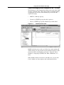
Figure 5.3
Scanlist Page in the Scanner Module Dialog Box
8. Under Scanlist, select the encoder, and then click Edit I/O
Parameters. The Edit I/O Parameters dialog box appears.
5-6
Configuring a Scanner to Communicate with the Encoder
Figure 5.4
Edit I/O Parameters Dialog Box - COS
9. Select the type(s) of data exchange (Polled, Change of State,
and/or Cyclic). In our example, we selected Change of State.
10. Type the number of bytes that will be required for your I/O in the
Rx Size and Tx Size. See Assembly Data Format, page B-4, for
data sizes.
11. Set the scan rate:
Data
Exchange
Rate to set
Polled
Polled Rate
Change of
State
Heartbeat
Rate
Cyclic
Send Rate
Click Help for more information.
12. When using COS in high speed and/or high resolution
applications, it may be necessary to limit how often the device
will report to the master in order to lessen network traffic. To do
so requires either setting the hysteresis to over 10% of the
‘RESOLUTION PER REVOLUTION’ value or increasing the
‘Inhibit Time’. To increase the inhibit time to 10ms, click on the
Advanced... button under ‘Change of State/Cyclic.’ Adjust the
Inhibit Time and click OK.
Configuring a Scanner to Communicate with the Encoder
Figure 5.5
5-7
Inhibit time
13. In the Edit I/O Parameters box, click OK. If you changed any
settings, a Scanner Applet appears and asks if it is OK to unmap
the I/O. Click Yes to continue. The Edit I/O Parameters dialog
box closes and then the Scanner Module dialog box (Figure 5.3)
reappears. You will map the I/O in the next section in this chapter.
Mapping the Product’s Data in
the Scanner
Data from I/O messages must be mapped in the scanner. This
mapping determines where a ladder logic program can find data
transmitted on the network.
Mapping the Input I/O
In the Scanner Module dialog box, click the Input tab. (If you need to
display this dialog box, right-click the scanner in the configuration
view. See Figure 5.1.). Below, the input pages for Change of State,
Polled and Strobed are shown.
Figure 5.6
Scanner Module Dialog Box, Input Page - COS
5-8
Configuring a Scanner to Communicate with the Encoder
Figure 5.7
Scanner Module Dialog Box, Input Page - Polled
Figure 5.8
Scanner Module Dialog Box, Input Page - Strobed
If you selected the Automap on Add box (Figure 5.2) in the
Scanlist page (Figure 5.3) and did not change any settings,
RSNetWorx has already mapped the I/O. If I/O is not mapped,
click AutoMap to map it. If you need to change the mapping,
click Advanced and change the settings. Click Help for
assistance.
Saving the Configuration
After configuring a scanner, you must download it to the scanner. You
should also save it to a file on your computer.
1. In the Scanner Module dialog box, click Apply to save the
configuration to the scanner. A Scanner Configuration Applet
appears and asks if it is OK to download the changes.
2. Click Yes to download the changes. The changes are downloaded
and then the Scanner Module dialog box reappears.
3. Click OK to close the Scanner Module dialog box.
4. Select File > Save. If this is the first time that you saved the
project, the Save As dialog box appears. Navigate to a folder, type
a file name, and click Save to save the configuration to a file.
Chapter
6
Using DeviceNet Explicit
Messaging
Chapter Objectives
Chapter 6 provides information you need to monitor and configure
the encoder using explicit messaging on DeviceNet. In this chapter,
you will read about the following:
•
Required equipment.
•
Messaging guidelines for the 1747-SDN scanner.
•
An Explicit Messaging example.
Refer to Appendix B, DeviceNet Objects, for information on object
data support.
Required Equipment
Before using messaging, your PC must be:
•
Running RSLogix500 and RSLinx if you are using an SLC. Refer
to http://www.software.rockwell.com for more information on
these products.
•
Running RSLogix5000 and RSLinx for Logix platforms. Refer to
http://www.software.rockwell.com for more information on these
products.
•
Connected to and communicating with the controller.
!
Explicit Messaging
Examples
ATTENTION: The PRESET function results in a
change of position reading. This can cause unexpected
motion which could result in personal injury and damage
to the product or equipment. During PRESET, steps
should be taken to ensure the shaft is stationary and will
remain so.
Explicit Messaging Preset Example for the 1747-SDN
Scanner
The SLC copies an Explicit Message into the scanner’s M0-file.
When the copy is completed the scanner moves the message into a
queue for processing. Up to 10 Explicit Messages can be in this
queue.
When the scanner receives a response message it is placed into a
queue. The first response in the queue is available from the M1-file.
When the message delete command is copied into the scanner the
message is complete and the next available response will appear in
the M1-file.
6-2
Using DeviceNet Explicit Messaging
In this example a value is sent to the preset attribute in the encoder.
The encoder stores the preset value sent in non-volatile memory.
Storing the preset value applies the preset value to the encoder
position value.
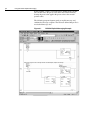
The following program fragment sends an explicit message and
confirms the message reception. The N20 user defined integer file is
used to hold message data:
Figure 6.1
1747SDN Explicit Messaging Example
Using DeviceNet Explicit Messaging
6-3
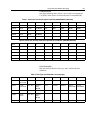
Example Values
One of the following tables of data is sent to and received from the
1747-SDN. Values shown are in hexadecimal (even the MAC ID).
Table 1: Preset (set service) Example to position 00 00 00 00h (0 decimal)
Offset
0
1
2
3
4
5
6
7
N20:0
00 04
-
-
-
-
-
-
-
N20:10
02 01
00 0A
10 MacID
002F
0001
000A
00 00
00 00
...
-
-
-
-
-
-
-
-
N20:50
02 01
00 00
90 MacID
-
-
-
-
-
-
-
-
-
-
-
Table 2: Preset (set service) Example to position 01 35 D0 B2h (20304050 decimal)
Offset
0
1
2
3
4
5
6
7
N20:0
00 04
-
-
-
-
-
-
-
N20:10
02 01
00 0A
10 MacID
002F
0001
000A
D0 B2
01 35
...
-
-
-
-
-
-
-
-
N20:50
02 01
00 00
90 MacID
-
-
-
-
-
-
-
-
-
-
-
Data Description
The table below defines the data types and is followed by their
definitions.
Table 3: Data Type (see definitions on next page)
Offset
0
1
2
3
4
5
6
7
N20:0
Delete
Block Cmd
-
-
-
-
-
-
-
N20:10
TX ID,
Command
Port, Size
Service
Req,
MacID
Class
Instance
Attribute
Preset
ValueLSW
Preset
ValueMSW
...
-
-
-
-
-
-
-
-
N20:50
RX ID,
Status
Port, Size
Service
Rsp,
MacID
-
-
-
-
-
-
-
-
-
-
-
6-4
Using DeviceNet Explicit Messaging
TXID:
This is a one-byte integer the range of 1 to 255. The scanner
uses this value to track the transaction to completion, and
returns the value with the response that matches the
request.
SERVICE REQ/RSP:
The DeviceNet service request and response:
10 = Set Service Request
0 = Set Service Response
STATUS:
For each upload, the status code provides the processor
with status on the device and its response:
0 = Ignore transaction block (block empty)
1 = Transaction completed successfully
2 = Transaction in progress (not ready)
3 = Error — Slave not in scan list
4 = Error — Slave off-line
5 = Error — DeviceNet port disabled or off-line
6 = Error — Transaction TXID unknown
8 = Error — Invalid command code
9 = Error — Scanner out of buffers
10 = Error — Other client/server transaction in progress
11 = Error — Could not connect to slave device
12 = Error — Response data too large for block
13 = Error — Invalid port
14 = Error — Invalid size specified
15 = Error — Connection busy
MAC ID:
The DeviceNet network address of device where the
transaction is sent. This value can range from 0 to 63. The
slave device must be listed in the scanner module's scan list
and be on-line for the Explicit Message transaction to be
completed.
See appendix B of the encoder manual for class/attribute
values, access rules, and data types.
COMMAND:
A code that instructs the scanner how to administer the
request:
1 = Execute this transaction block
4 = Delete this transaction block
PRESET VALUEMSW / VALUELSW:
This quadword value (limited to 03 FF FF FF) is stored in
non-volatile memory when the set service is used. Storing
the preset value applies the preset value to the encoder
position value.
PORT:
The port must be zero (Channel A) on a 1747-SDN scanner.
SIZE:
The size of the transaction body in bytes. The transaction
body can be up to 29 words (58 bytes) in length. If the size
exceeds 29 words, an error code will be returned.
CLASS:
002Fh is the encoder class
INSTANCE:
There is only one instance of the encoder - 0001h
ATTRIBUTE:
The value 000Ah is the Preset Value attribute.
Using DeviceNet Explicit Messaging
6-5
Explicit Messaging Preset Example for the 1756-DNB
The following is a code segment that will preset the value of the 842D
encoder’s ‘Position Value’. This can be useful for automatic homing
or automated error recovery. The following tags are used for the
explicit messaging:
•
MSGY is a Message type tag
•
Lsource is a UDINT type tag the value is preset to
•
Ldest is a UDINT type tag that should always return with 0.
Figure 6.2
Position Value Preset
MSGY needs the service code (set) 10, the class code (encoder) 2F,
and the instance 01 (only instance) for the attribute 0A (Preset). The
preset data will be sent from the tag ‘Lsource.’ Since the ‘Preset’
attribute is a long integer (UDINT), the ‘Num. Of Elements’ is 4
bytes.
Other attributes maybe read (service code 0E) or set ( service code
10) in a similar way. Any response data would return in Ldest.
6-6
Using DeviceNet Explicit Messaging
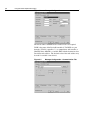
Figure 6.3
Message Configuration
The details where communication is addressed are also required.
'DNB' is the name of the DeviceNet module (1756-DNB) at a port
from the (1756-L1) controller, '2', to communicate with encoder at
'MACID' where MACID is a variable SINT with the destination slave
DeviceNet node address. The decimal value of the node address may
be used if a variable is not desired.
Figure 6.4
Message Configuration - Communication Tab:
Appendix
Specifications and Dimensions
842D Specifications
Electrical
Code Format
Natural Binary
Code Direction
CW or CCW (programmable)
Electrical Interface
DeviceNet Specification release 2.0
Operating Voltage
11-25V DC
Power Consumption
1.8W (75mA @ 24V DC)
Max # of Steps/Revolution
8192
Max # of Revolutions
8192
Position Forming Time
0.3msec
Delay on Power Up
1050msec
Reset
Via covered rear button
EEPROM Write Life
Greater than 100,000 cycles
Mechanical
Angular Acceleration
5 x 10⁵ radians/sec2
Moment of Inertia
35gcm2 (5.0 x 10⁻⁴oz-in-sec2)
Operating Speed
6000 RPM at max shaft loading
Maximum Working Speed
12,000 RPM
Starting Torque
2.5Ncm (3.5oz-in)
Shaft Loading
Axial 11lb (50N), Radial 67lb (300N)
Environmental
Housing
Aluminum
Operating Temperature
-20°C to 85°C (-4°F to +185°F)
Max Working Temperature
-40°C to 100°C (-40°F to +212°F)
Storage Temperature
-40°C to 125°C (-40°F to +257°F)
Humidity
98% Noncondensing
Protection
NEMA Type 4, 13, IP66 (IEC 529)
Shock
100g/6msec
Vibration
20g (58 to 2000Hz),
1.5mm displacement (10 to 58Hz)
Approximate Weight
0.91kg (2lbs)
A
A-2
Specifications and Dimensions
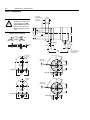
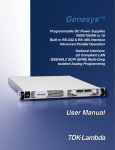
842D Dimensions
9.98/9.99
(0.392/0.393)
!
ATTENTION: Rigidly
coupling the encoder shaft
to the machine shaft will
cause a failure in either the
bearings of the encoder or
the bearings of the machine
shaft.
18/20
(0.71/0.79)
8.8/9.2
(0.34/0.37)
18
(0.71)
∅59.5 35.94/35.98
(2.34) (1.415/1.416)
76
(2.99)
Flexible Shaft Couplings
∅53.8
(2.12)
Angle
10
(0.39)
3
(0.12)
Parallel
Off-Set
13
(0.51)
6
(0.24)
X
15.5
(0.61)
27.8
(1.09)
Screw Cover for
DIP Switches and
Reset Button
105.8
(4.16)
Diagnostic
LEDs
120˚
35˚
M4 3 Plcs
7 (0.28) deep)
∅48 ±0.1
(1.89)
Single QD
Single QD
65
(2.56)
Diagnostic
LEDs
120˚
35˚
M4 3 Plcs
7 (0.28) deep)
∅48 ±0.1
(1.89)
Double QD
Double QD
65
(2.56)
Appendix
B
DeviceNet Objects
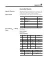
Appendix Objectives
Appendix B defines the DeviceNet object classes, class services, and
attributes that are supported by the DeviceNet encoder. This appendix
assumes that you have experience in object programming.
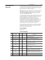
Object Classes
The 842D DeviceNet encoder supports the following object classes:
Class
Class Code 01hex — Identity
Object
Object
Page
01hex
Identity
B-1
02hex
Message Router
B-2
03hex
DeviceNet
B-2
04hex
Assembly
B-3
05hex
Connection
B-5
2Fhex
Encoder
B-7
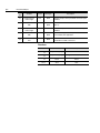
The identity object provides identification and general information
about the device.
Class Attributes
Not supported.
Instance Attributes
Attr.
ID
Attribute
Access
Data type
Description
1
Vendor ID
Get
UINT
Allen Bradley = 1
2
Device Type
Get
UINT
Rockwell Misc., 115
3
Product Code
Get
UINT
10626
4
Revision
Get
UINT
4.001
5
Status
Get
WORD
6
Serial Number
Get
UDINT
7
Product Name
Get
Short String
842D MULTITURN
ENCODER
Services
Service Code
Service Name
Description
0Ehex
Get_Attribute_Single
Returns the attribute value
05hex
Reset
Value = 0
B-2
DeviceNet Objects
Class Code 02hex —
Message Router
The Message Router Object provides a messaging connection point
through which a client may address to any object class or instance
residing in the physical devices.
Class and Instance Attributes
Not supported.
Services
Not supported.
Class Code 03hex —
DeviceNet
The DeviceNet Object is used to provide the configuration and status
of a physical attachment to DeviceNet. A product must suppot one
(and only one) DeviceNet Object per physical network attachment.
Class Attributes
Attr.
ID
Attribute
Access
Data Type
Description
1
Revision
Get
UINT
Revision = 002
Instance Attributes
Attr.
ID
Attribute
Access
Data Type
Description
1
Node address
Get
USINT
Range 0-63
2
Baud Rate
Get
USINT
Range 0-2
3
BOI
Get
BOOL
Value=1
4
Bus-OFF-Ctr.
Get/Set
USINT
5
Allocation
Information
Get
Struct. of:
BYTE
USINT
Allocation choice byte
master’s Node Address
Services
Service
Code
Service Name
Description
0Ehex
Get_Attribute_Single
Returns the attribute value
10hex
Set_Attribute_Single
Changes the attribute value
4Bhex
Allocte_Master/
Slave_Connection_Set
Predefined master/slave
connection set is requested
DeviceNet Objects
Class Code 04hex —
Assembly
B-3
The Assembly Object combines attributes from different objects into
a single object. For a detailed view of the assembly data format, see
page B-4.
Class Attributes
Attr.
ID
Attribute
Access
Data Type
Description
1
Revision
Get
UINT
Revision = 002
Instance Attributes
Instance
ID
Attr
ID
Attribute
Access
Data
Type
Description
1
3
Data
Get
ARRAY
Position value
2
3
Data
Get
ARRAY
Position+Warning
Flag+Alarm Flag
3
3
Data
Get
ARRAY
Position + Velocity
4
3
Data
Get
ARRAY
Position + CAM
Services
Service code
Service name
Description
0Ehex
Get_Attribute_Single
Returns the value of an attribute
B-4
DeviceNet Objects
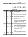
Assembly Data Format
Instance
Byte
Bit 7
Bit 6
Bit 5
Bit 4
Bit 3
Bit 2
Bit 1
0
Bit 0
LSB
1
Position value (Att. 12)
1
2
3
0
0
0
0
0
0
MSB
0
LSB
1
2
Position value (Att. 12)
2
3
0
0
0
0
0
4
0
MSB
Warning
flag (Att. 88)
reserved
0
Alarm flag
(Att. 85)
LSB
1
Position value (Att. 12)
2
3
3
0
0
0
0
0
0
MSB
4
LSB
5
Velocity value
(Not available in COS)
6
7
MSB
0
LSB
1
Position value (Att. 12)
2
4
3
0
0
0
0
0
0
MSB
Cam 3
Cam 2
Cam state
4
Cam 8
Cam 7
Cam 6
Cam 5
Cam 4
Position only
4 Bytes
Position + Flags
5 Bytes
Position + Velocity
8 Bytes
Position + Cams
5 Bytes
Cam 1
DeviceNet Objects
Class Code 05hex —
Connection
B-5
The Connection Class allocates and manages the internal resources
associated with both I/O and Explicit Messaging Connections. The
specific instance generated by the Connection Class is referred to as a
Connection Instance or a Connection Object.
Important: An externally visible interface to the Connection Class
across Explicit Messaging Connections exists. Unless otherwise
noted, all services/attributes noted in the following sections are
accessible using Explicit Messaging.
A Connection Object within a particular module actually represents
one of the end-points of a Connection. It is possible for one of the
Connection end-points to be configured and “active” (e.g.,
transmitting) without the other end-point(s) being present.
Connection Objects are used to model the communication specific
characteristics of a particular Application-to-Application(s)
relationship. A specific Connection Object Instance manages the
communication-specific aspects related to an end-point.
A Connection Object on DeviceNet uses the services provided by a
Link Producer and/or Link Consumer to perform low-level data
transmission and reception functions.
Class Attributes
Not supported
Instance Attributes
Attr.
ID
1
Attribute
State
Access
Data type
Get
USINT
State of the connection as defined in the
DeviceNet specification
Indicates I/O or Messaging connection
2
Instance_Type
Get
USINT
3
transportclass_tri
gger
Get
BYTE
4
Produced Cnxn
ID
Get
UINT
5
Consumed Cnxn
ID
Get
UINT
Get
BYTE
6
Initial Comm Char
7
Produced Cnxn
Size
Get
UINT
8
Consumed Cnxn
Size
Get
UINT
9
EPR
Get/Set
UINT
12
Watchdog Action
Get
USINT
Description
The Transport Class Trigger for this instance
CAN Identifier to transmit on
CAN Identifier to receive on
Defines the DeviceNet message groups that the tx/
rx Cnxn’s apply
Max bytes to transmit across this connection
Max bytes to receive across this connection
Expected Packet Rate
How to handle inactivity/watchdog timeouts
B-6
DeviceNet Objects
Attr.
ID
Attribute
Access
Data type
Description
13
Produced Cnxn
Path Length
Get
UINT
Number of bytes in the produced connection path
attribute
14
Produced Cnxn
Path
Get
ARRAY of
UINT
Path information of the desired assembly instance
(Def. 1)
15
Consumed Cnxn
Path Length
Get
UINT
Number of bytes in the consumed connection path
attribute
16
Consumed Cnxn
Path
Get
ARRAY of
UINT
Specifies the application object to receive the data
consumed by this application
Production inhibit
time
Get/Set
17
UINT
Defines minimum time between new data
production for COS connections
Services
Service Code
Service Name
Description
0Ehex
Get_Attribute_Single
Returns the value of an attribute
10hex
Set_Attribute_Single
Changes the value of an attribute
05hex
Reset
Reset
16hex
Save
Save
DeviceNet Objects
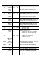
Class Code 2Fhex — Encoder
B-7
The Encoder Object contains all encoder data. All input data,
parameter data and status data are included here.
Class Attributes
Attr.
ID
Attribute
Access
Data Type
Description
1
Revision
Get
USINT
Revision = 01
2
Max. Instance
Get
USINT
1
Instance Attributes
Attr. ID
Attribute
Access
Data type
Description
1
Number of
attributes
Get
USINT
2
Attributes
Get
ARRAY
of USINT
3
Code
Sequence
Get/Set
BOOL
Direction control for counting. Defines the increasing 'POSITION
VALUE' as clockwise shaft rotation or counter clockwise as seen
facing the shaft (CW, CCW).
5
Scaling
function control
Get/Set
BOOL
Scaling Enable --Enabling scaling changes the 'POSITION
VALUE' I/O data resolution to 'MEASURING UNITS PER
REVOLUTION' and 'TOTAL MEASURING RANGE'
7
measuring
units per
revolution
Get/Set
UDINT
Number of distinguishable steps per revolution. Less than
physical resolution.
8
Total
measuring
range in
measuring
units
Get/Set
UDINT
The steps over total measuring range. The number is
automatically adjusted to a 2^0 - 2^13 multiple of 'RESOLUTION
PER REVOLUTION'.Example: if 'RESOLUTION PER
REVOLUTION' is set to 3600 then the possible 'TOTAL
MEASURING RANGE' values will be 3600, 7200, 14400, 28800,
... 29491200.
10
Preset value
Get/Set
UDINT
This value will be applied to the 'POSITION VALUE'.
Number of supported attributes
List of supported attributes
11
COS/delta
Get/Set
UDINT
A COS I/O message will be generated when the 'POSITION
VALUE' changes by this value. This value will be set to 5 if set to a
value larger than the 'TOTAL MEASURING RANGE'. Setting this
value to 0 disables COS messaging for 'POSITION VALUE'
changes. To lessen network traffic for high speed (4000 RPM+)
and/or high resolution (1024+ ppr) applications either: increase
the hysteresis to over 10% of the 'RESOLUTION PER
REVOLUTION' value, increase the 'Inhibit Time' ('Scanlist', 'Edit I/
O Parameters...', 'Advanced...') to 10 msec.
12
Position value
Get
UDINT
The current position value. This value is affected by 'PRESET
VALUE', 'RESOLUTION PER REVOLUTION', and 'SCALING
CONTROL'.
20
Velocity format
Get/Set
BYTE
This sets the format for velocity and acceleration values. The max
and min limits for velocity and acceleration are affected as well.
– 0 = Steps per second
–
1 = RPM
–
2 = RPS
B-8
DeviceNet Objects
Attr. ID
Attribute
Access
Data type
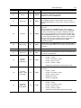
22
Velocity value
Get
DINT
This is the value of the current velocity according to unit type in
'VELOCITY FORMAT'
23
Minimum
velocity
Get/Set
DINT
Value of minimum velocity limit according to unit type of
'VELOCITY FORMAT'. A 'VELOCITY VALUE' under this limit will
cause a 'Min. Velocity Underrun' warning and set the warning flag.
24
Maximum
velocity
Get/Set
DINT
Value of maximum velocity limit according to unit type of
'VELOCITY FORMAT'. A 'VELOCITY VALUE' over this limit will
cause a 'Max. Velocity Exceeded' warning and set the warning
flag.
31
Acceleration
value
Get
DINT
Value of the current acceleration according to unit type of
'VELOCITY FORMAT'.
32
Minimum
acceleration
DINT
Value of minimum acceleration limit according to unit type of
'VELOCITY FORMAT'. An 'ACCELERATION VALUE' under this
limit will cause a 'Min. Accel. Underrun' warning and set the
warning flag.
33
Maximum
acceleration
Get/Set
DINT
Value of maximum acceleration limit according to unit type of
'VELOCITY FORMAT'. An 'ACCELERATION VALUE' over this
limit will cause a 'Max. Accel. Exceeded' warning and set the
warning flag.
40
CAM state
register
Get
BYTE
Get/Set
Description
State of all 8 cams. See “Designation of Cam Bits‘, page B-10:
– Bit 0=Cam_NO_1 State...
–
41
CAM polarity
register
Get/Set
BYTE
Polarity for the state of 8 independent CAMs (1-8), See
“Designation of Cam Bits‘, page B-10:
– 1 cam state will be active outside of the cam limits
–
42
CAM enable
register
Get/Set
BYTE
Bit 7=Cam_NO_8 State
0 cam state will be active inside of the cam limits
Enable / Disable 8 independent CAMs (1-8). See “Designation of
Cam Bits‘, page B-10:
– 1 cam state will be affected by position
–
0 cam state will always be 0
43, 46, 49,
52, 55, 58,
61, 64
CAM X low limit
(0 ≤ X < 8)
Get/Set
UDINT
This is the Switch point for this cam's lower limit. The value must
be less than the 'CAM HYSTERESIS' for this cam and less than
the 'TOTAL MEASURING RANGE'
44,47,50,
53, 56, 59,
62, 65
CAM X high
limit (0 ≤ X < 8)
Get/Set
UDINT
This is the Switch point for this cam's upper limit. The value must
be less than the 'TOTAL MEASURING RANGE'.
45,48,51,
54, 57, 60,
63, 66
CAM X
hysteresis
(0 ≤ X < 8)
Get/Set
UINT
This value will be added to the 'CAM (1) HIGH LIMIT' and
subtracted from the 'CAM (1) LOW LIMIT' when calculating the
cam state. This value must be less than 'CAM (1) LOW LIMIT'.
80
Operating
status
Get
USINT
The 'Direction: CCW' and 'Scaling: On' indicators show enabled
modes for 'CODE SEQUENCE' and 'SCALING CONTROL'.
81
Single-turn
resolution
Get
UDINT
This is the physical number of steps per revolution. This is the
maximum number for 'RESOLUTION PER REVOLUTION'.
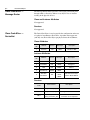
82
Number of
distinguishable
revolutions
Get
UINT
This is the number of revolutions the encoder will rotate before the
'POSITION VALUE' rolls over to 0. Must be a multiple of 2
between 20 and 213.
DeviceNet Objects
B-9
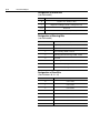
Attr. ID
Attribute
Access
Data type
83
Alarms
Get
WORD
Malfunction could lead to incorrect position value. See
“Designation of Alarm Bits‘, page B-10.
Any alarm will set the 'ALARM FLAG'.
BOOL
This flag indicates a device failure that requires user intervention.
The 'ALARMS' indicate the specific failure. This value will be
reported if 'INPUT ASSY.' is set to 'Position + Flags' as bit 0 of the
5th byte.
85
Alarm flag
Get
Description
86
Warnings
Get
WORD
Internal parameters exceeded. See “Designation of Warning Bits‘,
page B-10.
Any warning will set the 'WARNING FLAG'. The 'Frequency
Exceeded' warning is caused by rotating faster then 6000 RPM.
The Velocity min/max flag is caused by a 'VELOCITY VALUE'
under or over the velocity limits. The Acceleration min/max flag is
a 'ACCELERATION VALUE' under or over the acceleration limits.
The 'Cam Limits Out of Order' flag is caused by a set of cam limits
where the hysteresis value is larger then the cam lower limit, or
the higher or lower limit that is greater than the 'TOTAL
MEASURING RANGE'.
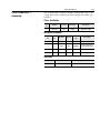
88
Warning flag
Get
BOOL
Indicates if any of the 'WARNINGS' are active. This value will be
reported if the 'INPUT ASSY’ is set to 'Position + Flags' as bit 1 of
the 5th byte."
90
Operating time
Get
UDINT
Stores operating time for the encoder in operating hours.
91
Offset value
Get
DINT
The offset value is calculated by the preset function. Shift position
value by the calculated value.
The type of input data that is sent for the Polling I/O connections.
– Position = 4 bytes
111
112
Assembly
Number Polling Mode
Assembly
Number - COS/
Cyclic Mode
Get
USINT
–
Position + Cam State = 5 bytes
–
Position + Flags = 5 bytes
–
Position + Velocity = 8 bytes
–
Update time: Velocity 50 mS, other modes 0.3 mS
The type of input data that is sent for the Change of State I/O
connections.
– Position = 4 bytes
Get
USINT
–
Position + Cam State = 5 bytes
–
Position + Flags = 5 bytes
–
Update time: 0.3 mS
–
Velocity not supported.
The type of input data that is sent for the Strobed I/O connections.
– Position = 4 bytes
113
Assembly
Number - Bit
Strobed Mode
Get
USINT
–
Position + Cam State = 5 bytes
–
Position + Flags = 5 bytes
–
Position + Velocity = 8 bytes
–
Update time: Velocity 50 mS, other modes 0.3 mS.
B-10
DeviceNet Objects
Designation of Alarm Bits
(see Attribute 83)
Bit
Description
0
Position error: 0=NO, 1=YES
1
Diagnostic: 0=Diagnostic OK, 1=Diagnostic error
2...11
Reserved
12...15
Manufacturer specific (not used)
Designation of Warning Bits
(see Attribute 86)
Bit
Description
0
Frequency exceeded: 0=NO, 1=YES
1
Light control reserve: 0=Not reached, 1=Error
2
CPU watchdog: 0=OK, 1=Reset
3
Operating time limit warning: 0=NO, 1=YES
4
Reserved
5
Reference point: 0=Reached, 1=Not reached
6
Minimum Velocity Flag: 0=OK, 1=Under
7
Maximum Velocity Flag: 0=OK, 1=Over
Designation of Cam Bits
(See Attributes 40, 41, 42)
Bit
Description
0
Cam 1 state
1
Cam 2 state
2
Cam 3 state
3
Cam 4 state
4
Cam 5 state
5
Cam 6 state
6
Cam 7 state
7
Cam 8 state
Index
Numerics
842D
configuring to communicate with a
scanner 5-1
default settings 3-1
function 1-1
installation 2-1
setting up 1-2
specifications A-1
1747-SDN Scanner 6-1
1756-DNB/A 5-4
A
Accessing and Editing Parameters 4-5
Alarm Bits B-10
Assembly B-3
Audience for this manual P-1
Automap on Add 5-5
B
Baud rate 3-2
Bit Strobe 5-3
Bus termination 3-2
Bus Termination Switches 3-3
C
Cables
selecting 2-1
Cam Bits B-10
Change of State 5-2
Characteristics 5-1
Class Instance Editor 4-5, 4-7
Communicate with the Encoder 5-1
Configuration 5-8
Configuration modes 4-5
Configure Drivers 4-2
Configuring a Scanner 5-1
Configuring the DIP Switches 3-1
Connection B-5
Conventions Used in this Manual P-5
COS 5-2
Cyclic 5-2
D
Daisy chain connections 2-1
Data exchange 5-6
Default Values 4-7
Designation of Alarm Bits B-10
Designation of Cam Bits B-10
DeviceNet B-2
definition P-3
overview 1-1
DeviceNet Drivers 4-2
DeviceNet objects B-1
connection B-5
DeviceNet B-5
identify B-1
message router B-3
register B-7
Diagnostic LED 3-3
DIP Switches 3-1
Driver 4-2
Drop cable 2-1
E
Edit I/O Parameters 5-5
EDS file 4-4
EDS Wizard 4-4
EEPROM 3-3
EEPROM Values 4-7
Electronic Data Sheet 4-4
Encoder B-7
Encoder object 4-7
Enhanced Device Configuration 4-5, 4-6, 4-7
Examples 6-1
Explicit Messaging 6-1
I–2
Index
F
Features 1-1
N
Node Address 3-2
G
Going Online 4-2
Graph View 4-4
Groups 4-6
O
Objects, refer to DeviceNet objects
Offline Integration 4-4
Operating Modes 5-1
Operating modes 5-2
Overview 1-1
H
Heartbeat Rate 5-6
I
I/O messaging 5-1
Identity Object B-1
In Offline Mode 4-6
In Online Mode 4-7
Inhibit Time 5-6
Input data 5-2
Installation 2-1
L
Limitations of the trunk and drop cables 2-2
M
M0-file 6-1
M1-file 6-1
MAC ID 6-3
Manual
audience P-1
contents P-2
conventions P-5
purpose P-1
Mapping the Input I/O 5-7
Message buffer 6-2
Message connections 5-2
Message Router B-2
Messaging
examples 6-4–6-5
explicit
1747-SDN scanner 6-1
Micro Connections 2-1
Modify encoder parameters 4-5
P
Parameter values 4-5
Parameters
Pin configurations 2-1
Polled Rate 5-6
Polling 5-2, 5-3
PORT 6-3
POSITION VALUE 3-3
Preset function 3-3
Protocols 5-1
R
Read-only 4-6
Read parameters 4-5
Recommended cables. 2-1
Related Publications P-2
Remote setting of the DIP switches 3-3
Request and Response messages 6-1
Reset service 4-5
Restore service 4-5
Rockwell Automation Support P-5
RSNetworx 4-4
RSNetWorx for DeviceNet 4-1
creating an EDS file 4-4
editing parameters with 4-5
going online 4-2
setting up a scan list with 5-4
using to map I/O 5-7
web site 5-1
Rx Size 5-6
Index
S
Safety Precautions P-3
Save 4-7
Saving Parameter Values to EEPROM 4-7
Scan List 5-4
Scan rate 5-6
SCANport
cables 2-1
Selecting Cables 2-1
Send Rate 5-6
SERVICE 6-3
Setting Parameters to Default Values 4-7
Setting Parameters to EEPROM Values 4-7
Setting the baud rate 3-2
Setting the Node Address 3-2
Setting Up the Encoder 1-2
SLC
explicit messaging example 6-4
Specifications A-1
STATUS 6-3
T
Technical support P-5
Termination resistor 3-2
Terms and Abbreviations P-3
Terms and abbreviations P-3
Time delay 5-3
Transaction body 6-2
Transaction header 6-2
Transaction ID 6-3
Transmission baud rate 3-2
Trunk cable 2-1
Tx Size 5-6
TXID 6-3
U
Update cycle time 5-2
Upload 5-4
W
Warning Bits B-10
I–3
I–4
Notes:
Index
RSLinx, RSNetWorx, RSLogix5, RSLogix500 and RSLogix 5000 are trademarks of Rockwell Automation.
PLC and PLC-5 are registered trademarks of Rockwell Automation.
SLC and SLC-5/03 are registered trademarks of Rockwell Automation.
DeviceNet is a trademark of the Open DeviceNet Vendor Association.
Windows and Microsoft are either registered trademarks or trademarks of Microsoft Corporation.
Back Cover
ZZZURFNZHOODXWRPDWLRQFRP
BBBBBBBBBBBBBBBBBBBBBBBBBBBBBBBBBBBBBBBBBBBBBBBBBBBBBBBBBBBBBBBBBBBBBBBBBBBBBBBBBBBBBBBBBBBBBBBBBBBBBBBBBBBBBBBB
3RZHU&RQWURODQG,QIRUPDWLRQ6ROXWLRQV+HDGTXDUWHUV
$PHULFDV5RFNZHOO$XWRPDWLRQ6RXWK6HFRQG6WUHHW0LOZDXNHH:,86$7HO )D[ (XURSH0LGGOH(DVW$IULFD5RFNZHOO$XWRPDWLRQ9RUVGDDQ%RXOHYDUGGX6RXYHUDLQ%UXVVHOV%HOJLXP7HO )D[ $VLD3DFLILF5RFNZHOO$XWRPDWLRQ/HYHO&RUH)&\EHUSRUW&\EHUSRUW5RDG+RQJ.RQJ7HO )D[ 3XEOLFDWLRQ'80%(13²-DQXDU\
&RS\ULJKW5RFNZHOO$XWRPDWLRQ$OOULJKWVUHVHUYHG3ULQWHGLQ86$