1
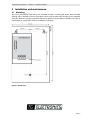
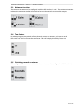
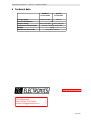
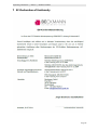
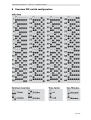
Coin machine
EMS-5x
(from 01/2015)
Operating instructions
www.tgelectronics.no
Vidhaugen 114
7550 Hommelvik
Tele:73979017-91795392
e-post: [email protected]
Beckmann GmbH © 2015
13.01.2015
Operating instructions | EMS-5x | Beckmann GmbH
Page 2
Operating instructions | EMS-5x | Beckmann GmbH
All rights reserved. No part of this manual may be reproduced or copied in any way without
authorization of the Beckmann GmbH.
The Beckmann GmbH is not liable to the buyer or other persons for damages, losses, costs or
expenses, that are caused by the buyer or other persons by accident, misuse, unauthorized
changes, repair or innovations of the product. Furthermore the Beckmann GmbH is not liable for
losses, costs, faults or consequential losses , that may emerge by using this product. The technical
data correspond to the current conditions. Misprints, errors or changes reserved.
Vidhaugen
114
Beckmann GmbH
Brandtstraße
1
7550
Hommelvik
33161 Hövelhof
Tele:73979017-91795392
Fon +49 (0) 52 57 - 98 23 – 0
Fax +49 (0)
52 57 - 98 23 – 11
e-post:
[email protected]
[email protected]
www.beckmann-gmbh.de
Page 3
Operating instructions | EMS-5x | Beckmann GmbH
Page 4
Operating instructions | EMS-5x | Beckmann GmbH
Table of contents
1 Features.......................................................................................................7
1.1 Common features of the EMS-56 and EMS-57.........................................................................7
1.2 Special features of the EMS-56...................................................................................................... 7
1.3 Special features of the EMS-57...................................................................................................... 7
2 Safety precautions......................................................................................7
3 Installation and maintenance....................................................................8
3.1 Mounting............................................................................................................................................... 8
3.2 Electrical installation.......................................................................................................................... 9
4 Operation..................................................................................................11
4.1 Selling time with the EMS-56....................................................................................................... 11
4.2 Selling time with the EMS-57....................................................................................................... 11
4.3 Door opener (optional feature ) EMS-56-TE/EMS-57-TE.....................................................11
5 Programming............................................................................................12
5.1 General notes.................................................................................................................................... 12
5.2 Basic time (DIP-switches 1-6)....................................................................................................... 12
5.3 Minimum insertion.......................................................................................................................... 14
5.4 Time-factor......................................................................................................................................... 14
5.5 Switching seconds or minutes.................................................................................................... 14
6 Technical data...........................................................................................15
7 EC-Declaration of Conformity..................................................................16
8 Overview DIP-switch configuration........................................................17
List of figures and tables
Figure 1 : Dimensions........................................................................................................................................ 8
Figure 2 : Connection diagram standard version 230V (left), special version 24V (right).........9
Figure 3 : Handling instructions for wire connection..........................................................................10
Page 5
Operating instructions | EMS-5x | Beckmann GmbH
1 Features
1.1 Common features of the EMS-56 and EMS-57
•
•
•
•
•
•
mechanical coin selector, available for different types of coins
programmable minimum insertion (1 up to 4 coins)
programming via DIP-switches
from 1 seconds up to 640 minutes per coin selectable
maximum time up to 99 days
door opener for washing machines (optional)
1.2 Special features of the EMS-56
•
•
one-digit LED-display
number of inserted coins is displayed (time is not displayed)
1.3 Special features of the EMS-57
•
•
•
three-digit LED-display
remaining time is displayed
24 V version available (optional)
2 Safety precautions
The coin operated timers of the EMS-56/57 series are built by the state of technology and the
generally accepted safety-related rules. Nevertheless there may occur risks for the user or other
persons as well as impairments of the device or other values. Use the device only under faultless
conditions, as well as due, safety- and risk-conscious regarding the user manual!
Especially eliminate faults, that may impair safety, immediately! Keep the user manual always on
site of the device! Pay attention - additional to the user manual- to the general valid legal and
other obligatory rules such as accident prevention and environmental protection! Do not make
any changes and/or modifications without the authorization of the manufacturer. Spare parts have
to correspond to the manufacturer-defined standards. This is only guaranteed, if original spare
parts are used. Maintain the required or within this manual stated deadlines for repeating
maintenance intervals! Provide a safe and non-polluting disposal of plastic or electrical
replacement parts!
This coin operated timers are exclusive designed for managing different electric devices in rooms.
Any other or further use is not provided. The manufacturer is not liable for losses, that result from
misuse. A due use contains to heed the user guide and to observe the terms of service and
maintenance as well.
Page 6
Operating instructions | EMS-5x | Beckmann GmbH
3 Installation and maintenance
3.1 Mounting
The unit is provided for fixed wiring and assembly in rooms. For fixing the device there are three
drillings with a diameter of 6 mm at the back side. It must be taken care, that the case is mounted
vertically, otherwise a proper operation of the coin selector may be reduced. The EMS-56/57 has to
be mounted at a solid wall in order to avoid heavy vibrations.
Figure 1 : Dimensions
Page 7
Operating instructions | EMS-5x | Beckmann GmbH
3.2 Electrical installation
The installation of the EMS-56/57 is limited to the connection of the main power supply and the
switched outputs according to the connection survey:
CAUTION :
Arrange that the mounting is accomplished by an authorized electric company. The
electrical connection must be performed by an electrically skilled person !
Electrically skilled and qualified personnel must be able to read and understand
electric circuit diagrams, to commission and maintain electrical systems, to wire
switch and control cabinets, to install controlling software, to ensure proper
functioning of electrical components and to identify possible hazards in the work
with electric and electronic systems.
Since this is a stationary device with a fixed main power supply, an RCBO must be
installed on the installation side!
Figure 2 : Connection diagram standard version 230V (left), special version 24V (right)
Requirements:
•
main power supply is power-less
•
RCBO is switched off
The following wire cross sections must be used for connection:
•
Conductor cross section (1 wire):
2,5 mm²
•
Conductor cross section stranded:
2,5 mm²
•
Conductor cross section stranded
(in ferrule without plastic collar):
1,5 mm²
Stripping length:
8-9 mm
Page 8
Operating instructions | EMS-5x | Beckmann GmbH
The clamps are equipped with CAGE CLAMP ® connection technology for slotted screwdriver
operation only.
The following sequence must be followed during the electrical installation (see Figure 3):
1. Insert a flat-head screwdriver (3x100) in the square clamp opening and possibly
exert a slight pressure on the spring. Do not turn the screwdriver!
2. Insert the stripped wire through the round clamp opening into the opened spring
cage.
3. Remove the screwdriver.
4. Check the fixed position of the conductor by gently pulling the cable!
CAUTION:
Do not push the wire into the square clamp opening!
Do not push the wire into the clamp before clamp is fully opened ! (refer to
sequence above)
Otherwise, the contact is not sufficient and it may create sparks or fires!
Defects by a non-professional installation are not covered by the guarantee or
warranty - Liability for consequential damages are excluded!
Figure 3 : Handling instructions for wire connection
Page 9
Operating instructions | EMS-5x | Beckmann GmbH
4 Operation
4.1 Selling time with the EMS-56
The EMS-56 only displays the number of inserted coins via one-digit. The customer will not receive
any direct information about the bought time. If a coin is inserted into the EMS-56, the display
shows “1”.The output however will only be released, if the minimum insertion has been reached. A
blinking display signals, that the minimum insertion has not been reached yet. The display will
increase by one until an amount of 9 coins is reached. Furthermore it is possible to insert more
coins until the maximum time of 99 days is reached. An insertion of more than 9 coins is indicated
by the red dot mark.
CAUTION:
Coins, that are inserted after the maximum time of 99 days
has already been reached, will not get rated.
During operation, the displayed number of paid coins will continously be decreased by one
according to the consumption (remaining number of coins less than nine). If the complete time
has run out, the display changes to “0” and the output will be disabled.
4.2 Selling time with the EMS-57
The EMS-57 displays the remaining time until the output will be blocked. If a coin is inserted, the
released time will be displayed. The output however will only be released, if the minimum
insertion is reached. A blinking display signals, that the minimum insertion has not been reached
yet. An insertion of further coins increases the displayed time by the programmed amount. This
may be repeated until the maximum time of 99 days is reached.
CAUTION:
Coins, that are inserted after the maximum time of 99 days
has already been reached, will not get rated.
During operation, the remaining time is shown in the display of the coin machine. During
operation, the available time is counted down – a flashing red dot indicates this countown status .
If the complete time has run out, the display changes to “0” and the output will be disabled.
4.3 Door opener (optional feature ) EMS-56-TE/EMS-57-TE
The door opener is available as an optional feature. Some washing machines or dryers need power
in order to open the door. In order to support this devices, the EMS-56-TE/EMS-57-TE is customized
with a push button at the front side. By pressing this button, the output will be released for 10
seconds.
Page 10
Operating instructions | EMS-5x | Beckmann GmbH
5 Programming
5.1 General notes
CAUTION:
In order to program the EMS-56/57, the ISO housing within the EMS-56/57 has
to be opened . Since there is high voltage behind the cover, the main power
supply of EMS-56/57 must be power-less and RCBO must be switched off!
10x DIP-switches for programming the EMS-5x are available on the electronic-PCB:
•
•
•
•
A, DIP switches 1-6:
B, DIP switches 7-8:
C, DIP switch 9:
D, DIP switch 10:
Time base
Minimum insertion
Selecting time factor 1 or 10
Selecting seconds or minutes
5.2 Basic time (DIP-switches 1-6)
The basic time indicates the time, that will be released per every single coin. The basic time can be
configured with DIP-switches 1-6. The resulting time base is the sum of all activated values + 1:
Page 11
Operating instructions | EMS-5x | Beckmann GmbH
The following table shows all possible combinations:
Page 12
Operating instructions | EMS-5x | Beckmann GmbH
5.3 Minimum insertion
The minimum insertion can be configured with the DIP-switches 7 and 8. The minimum insertion
indicates the minimum number of coins, that have to be inserted to activate the output.
5.4 Time-factor
In order to program time-periods of more than 64 seconds or minutes, you have to set the
DIP-switch 9 to “ON” to activate the time-factor. This will multiply the time by factor 10.
5.5 Switching seconds or minutes
If the configured amount is counted as seconds or minutes can be configured with DIP-switch 10:
Page 13
Operating instructions | EMS-5x | Beckmann GmbH
6 Technical data
Energy supply
Power consumption
Output rating
Temperature of operation
Weight
Dimensions (W x H x D)
Standard
version 230V
Special
version 24V
230V AC/50Hz
24V AC
3W
max. 16A/230V
max. 16A/24V
0 to 40 °C with 30 to 70 % RH
2,5kg
162 x 260 x 110 mm
www.tgelectronics.no
Vidhaugen 114
7550 Hommelvik
Tele:73979017-91795392
e-post: [email protected]
Page 14
Operating instructions | EMS-5x | Beckmann GmbH
7 EC-Declaration of Conformity
Page 15
Operating instructions | EMS-5x | Beckmann GmbH
8 Overview DIP-switch configuration
Page 16