1
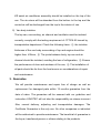
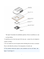
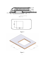
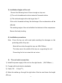
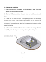
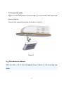
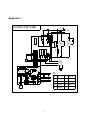
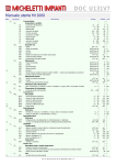
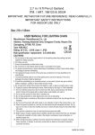
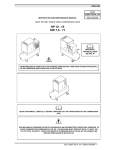
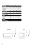
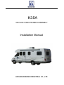
K35A VAN AIR CONDITIONER ASSEMBLY Installation Manual HEYUAN REXKING INDUSTRIAL CO., LTD Forward The correct installation is most important to ensure optimum utilities, to improve the reliability and economic and to reduce the downtime. The principle of the manual is to provide technical instruction on top – installed air conditioner assembly for the technicians before and after sales services. Read and follow the instruction mentioned in the user manual carefully. Moreover, it also provides the installation guideline on matching air conditioner manufacturers. 1 Content 1. Safety Precaution ············································································ 3 2. Technical Preparation Before Installation ······································· 4 3. Air Conditioner Guarantee ······························································ 5 4. Assembly Selection ········································································ 5 5. Installation Assembly ······································································ 6 6. Font panel commands ···································································· 12 7. Maintenance ··················································································· 12 8. Troubleshooting ·············································································· 13 Table1 ·································································································· 14 Table 2 ································································································· 15 Appendix1···························································································· 16 2 1.Safety Precaution 1). Wear working suit, working shoes when making operation. Do not wear slippers, short pants or waistcoat when installing the equipment. 2). Wear goggle or safety glasses preventing the dust or chips falling into the eyes when looking up. 3). Do not damage van body and the appearance of the air conditioner. Clean the carriage after installation. 4). Pay more attention to the position of oil tank when welding. Do not working near oil tank. 3 5). Check the isolation of the cable connection when connecting to 220V power supply. 6). The refrigerant will produce poisonous gases when there is bright fire. The personnel will suffocate or die when taking breathe the poisonous gases. The spray of the refrigerant will hurt the body. The protection is the most important before installation. Take the following methods if the refrigerant splashing into the eyes or on the skin: ① Wash eyes or damaged skin with lots of water (do not rub the eyes or skin); ② Apply the Vaseline on the skin; ③ Go to the hospital immediately for special treatment; 7). Do not refrigerate when closing the exhaust valve of the compressor, preventing the damages on personnel and machine due to high pressure. 8). Shut off the power supply when making repair, preventing the fireworks due to short circuit. 9). Be careful when drilling holes on the van. These holes might reduce the construction strength and result electric shock and fireworks. 10). Keep your hands far away from rotating parts, such as fan when the equipment is running. 2. Technical preparation before installation 1). Positioning the air conditioner 4 KR serial air conditioner assembly should be installed on the top of the van. The air return will be absorbed from the bottom to the top and the vented air will be discharged form the top to the interior of van. 2). Van body isolation The top van, surrounding, air channel and ventilator must be isolated correctly, comply with the testing requirement of JT/T216-95 issued by transportation department. Check the following items: ① the isolation thickness of the van body surrounding of top and engine should be higher than ≥30mm; ② The joints between body, top van and air channel should be isolated, avoiding the loss of refrigeration; ③ Ensure the performance of door and windows of the van; ④ The installation of all parts should be far from the heat source on considerations of repair and maintenance. 3. Guarantee We will provide maintenance and repair free of charge as well as replacement for damaged parts within 12 months guarantee from the date of sales. The guarantee will be ensured with our guideline and instruction. KINGTEC will not take the responsibility on misuse incorrect filter, normal delivery, adjusting and transportation damages. The Certificate Guarantee is the only one. No other companies or individual will be authorized to provide maintenance. The beneficial of guarantee is the buyer, transferred person or others relating to the products. 5 1). The maintenance will be made by the manufacturer within the guarantee. 2). The manufacture will not take the expense on the delivery charge due to the maintenance. . The Certificate Guarantee must be filled completely and send back to manufacturer for registration. See the Appendix 1 attached. 4. Assembly Selection 1). Selection: K35A is suitable installed on trailing car or van. The written approval must be provided by technical department if mounting the assembly on the MUT or industrial vehicles to ensure the guarantee. 2). Heating (Refrigerating): The capability of heating and refrigerating of the van depends on: The dimension of the van The thickness of the wall and isolation The size of the van windows and types The recommend length of K35A is 7 meters, with enough wall thickness and isolation layer no less than 25mm (foam or wool). The windows must have anti-explosion film or curtain. Use the best isolation material and double layer windows since the van is 6 working under high temperature(40ºC), ensure the best refrigeration. The total length will not be longer than 6 meters. 5. Installation Assembly 1). Roof strength There must be enough strength since the K35A air conditioner assembly is about 50kg. The top strength of normal car is not enough except the special vehicles with air conditioning required. Contact the car manufacturer on the top strength or provide enough supporting with H-type bracket. 2). Unit positioning 7 Figure 1 The figure1 describes the installation position of the air conditioner on van roof and ceiling. 1. Install the unit on the front part of the top van,ensure the unit exhaust in outdoor un-effect. 2. Do not install the unit at the place where affecting the air return or exhaust. Since it will affect the uniform of the temperature of inside van. 3. The location should be open to the centerline as the unit base, see figure 2 and figure 3. 8 AI R FLOW AI R FLOW Di r ect i on of car dr i vi ng Figure 2 Figure 3 9 3). Installation Angles of the unit Ensure the following items if there is angle on top van: (i) The unit is backboards incline instead of forwards incline. (ii) The inclined angle will no be larger than 7º. If the unit is forwards inclining, the discharge of the condensation will be affected. The working angle of the unit will affect the lubricant of the compressor. Ensure the body leveling. 4). Installation procedures Note:Cross the top van with crawl plate avoiding the damages on the protecting walls of top van. Must drill one hole through the top van:352×352mm. The holes are in the middle of the top van, supporting the unit. Preventing the hot air mixed into air return 5). The unit cable connection 1). Install the power supply of the unit on the right hands (352*352mm) ; 2). Comply with local electric standards. 3). Cable: RV :2.5mm2*3; 4). Make the cables go through the right side of the box and leave the length 400 mm. 10 6). Outdoor unit installation 1). Clean the holes and surrounding with the distance at least 75mm with grease after drilling the installed hole. 2). Stick the EVR stripe attached along the sides and seal the surface with glue; 3). Make the four fixing bolt tight, ensuring the gap 22mm for discharging between lower surface of the unit and top surface of the van. Observe the deforming of the assembly seat. Adjust the thickness of shock absorber rubber gasket for leveling. 4). Observe the installation of the air return outlet from the carriage. Seal the seat, EVR, joints of the top van, ensuring no leakage from the top van. ROOF STRUCTURE Figure 4 11 7). Connection cable Figure 5 is the connection of power supply. It is connected with insert and interior channel. Connect the adaptors properly as shown in Figure 5. Figure 5 8). Fix interior air channel With four M4 × 35 of the self-tapping screw fixation in the mounting bra ckets, 12 6.Font panel commands By pushing and releasing this button ,The unit power “on” or “off” 1) 2) M 3) By pushing and releasing this button,Select the Function mode By pushing and releasing this button,Set indoor 4) temp. By pushing and releasing this button, Set the fan speed NOTE:The fault code is displayed for failed programming,In this case,you need check the unit ALARM SIGNALLING Mess. Cause E1 Room probe failure E2 Evaporator probe failure E3 High press.compr. alarm 7 .Maintenance 1). Interior air return filter Clean the air return filter periodically. Generally speaking, the air return filter will be cleaned once a month. It will be cleaner once a week if it works in a dirty condition. The air return filter is visible. For example, the dark appearance shows the filter is clean, while the gray 13 appearance indicates the air return filter needed to be washed. Open the filter plate with screwdriver and take out the screen. Clean it with suds and dry. Put the filter into the right place. 8. Troubleshooting 1). Compressor not refrigerating Troubles Possible reasons No air after 1. Fuse broken turning on FAN 2. FAN switch damaged 1.Refrigerant filling not leaking Not refrigerating enough 2.Temperature too high Solution Check and replace Check and replace or Check the leakage and fill in the refrigerant Readjust the temperature control button 3.Interior temperature sensor broken or Check and replace defog temperature is unable to reset 4.Compressor damaged Check and replace 2). Air conditioner refrigerating not enough Troubles Possible reasons Solution 1.Incorrect selection Refrigerating intermittently Evaporator air not enough 2.HI switch protection: refrigerant filling too much, condensation blower damaged, condensation filter dirty and blocked Resetting air speed and temperature Discharge the redundant refrigerant slowly. Check and replace the condensation Clean the blower and condensation core Clean the filter dust screen or evaporator blade Clean the channel 1.Evaporator filter dust screen blocked or evaporator blade dirty 2. Air conditioner channel blocked 3.Evaporator blower fuse broken or Check and replace relay damaged 4.Evaportator blower damaged Check and replace Check air conditioner circuit and 5.Evaporator blower input too low grounding 14 Table 1 Customer Info Name ……………………………………………………………………………… Address……………………………………………………………………………… ……………………… P.C.…………………… Phone…………………………… Purchase Date…………………………………………………………………… Model ……………………………………………………………………………… S/N: ………… …………… …………… …… ………………… ……………… Install: ……………………………………………………………………………… Purchase Place…………………………………………………………………… Address……………………………………………………………………………… ……………………P.C. ……………………… Phone ……………………… 15 Table 2 Specification Model K35A Refrigeration 3500W Heating 2000W Power 115v 60HZ Consume Power 1510W Current Refrigerant R407c/700g Evaporation 650m3/h Dimension (L*W*H) 1050*595*245mm Assembly Weight 50kg Refrigerating conditions: Indoors dry ball 27.C, wet ball 19.5.C; Outdoors dry ball 35.C, wet ball 27.C. KINGTEC keeps the right on products changing without notification in advance. 16 Appendix 1 K35A ELECTRI C CLRCUI T DI AGRAM FUSE ~Power 6 2 3 KA FAN CM C C 5 EH T N H L EM C NOTE: HP Ai r r et ur n Tem i n- door heat exchange coi l Tem Cont r ol or 17 FU Fuse C Capaci t ance T Tr ansf or mer KA Power r el ay EM Evaporat or bl ower FAN Condenser f an EH El c Heat er CM Compr essor HP H. P Pr ot ect