1
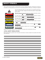
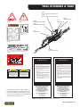
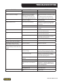
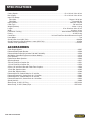
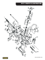
DS11
HYDRAULIC
DIAMOND SAW
Safety, Operation and Maintenance
USER MANUAL
© 2010 Stanley Black & Decker, Inc.
New Britain, CT 06053
U.S.A.
62211 12/2010 Ver. 4
DECLARATION OF CONFORMITY
DECLARATION OF CONFORMITY
ÜBEREINSTIMMUNGS-ERkLARUNG
DECLARATION DE CONFORMITE CEE
DECLARACION DE CONFORMIDAD
DICHIARAZIONE DI CONFORMITA
Hydraulic Tools
______________________________________________________________________
I, the undersigned:
Ich, der Unterzeichnende:
Je soussigné:
El abajo firmante:
lo sottoscritto:
Weisbeck, Andy
Surname and First names/Familiennname und Vornamen/Nom et prénom/Nombre y apellido/Cognome e nome
hereby declare that the equipment specified hereunder:
bestätige hiermit, daß erklaren Produkt genannten Werk oder Gerät:
déclare que l’équipement visé ci-dessous:
Por la presente declaro que el equipo se especifica a continuación:
Dichiaro che le apparecchiature specificate di seguito:
Concrete Cutting Chainsaw, Hydraulic
1.
Category:
Kategorie:
Catégorie:
Categoria:
Categoria:
2.
Make/Marke/Marque/Marca/Marca
3.
Type/Typ/Type/Tipo/Tipo:
4.
Serial number of equipment:
Seriennummer des Geräts:
Numéro de série de l’équipement:
Numero de serie del equipo:
Matricola dell´attrezzatura:
Stanley
DS113000, DS115000
All
Has been manufactured in conformity with
Wurde hergestellt in Übereinstimmung mit
Est fabriqué conformément
Ha sido fabricado de acuerdo con
E’ stata costruita in conformitá con
Directive/Standards
Richtlinie/Standards
Directives/Normes
Directriz/Los Normas
Direttiva/Norme
No.
Nr
Numéro
No
n.
Approved body
Prüfung durch
Organisme agréé
Aprobado
Collaudato
EN ISO
EN ISO
EN ISO
ISO
ISO
Machinery Directive
12100-1:2009
12100-2:2009
3744:2009
20643:2005
10726:1992
2006/42/EC:2006
Self
Self
Self
Self
Self
Self
5.
Special Provisions:
None
Spezielle Bestimmungen:
Dispositions particulières:
Provisiones especiales:
Disposizioni speciali:
6.
Representative in the Union: Patrick Vervier, Stanley Dubuis 17-19, rue Jules Berthonneau-BP 3406 41034 Blois Cedex, France.
Vertreter in der Union/Représentant dans l’union/Representante en la Union/Rappresentante presso l’Unione
Done at/Ort/Fait à/Dado en/Fatto a Stanley Hydraulic Tools, Milwaukie, Oregon USA
Signature/Unterschrift/Signature/Firma/Firma
Position/Position/Fonction/Cargo/Posizione
1/4/2011
2 ► DS11 User Manual
Engineering Manager
Date/Datum/le/Fecha/Data
1-4-11
TABLE OF CONTENTS
DECLARATION OF CONFORMITY........................................................................................................................................................................ 2
SAFETY SYMBOLS................................................................................................................................................................................................ 4
SAFETY PRECAUTIONS........................................................................................................................................................................................ 5
TOOL STICKERS & TAGS...................................................................................................................................................................................... 7
HOSE TYPES.......................................................................................................................................................................................................... 8
HOSE RECOMMENDATIONS................................................................................................................................................................................ 9
Figure 1. Typical Hose Connections.................................................................................................................................................... 9
HTMA REQUIREMENTS....................................................................................................................................................................................... 10
Figure 2. Maximum Chain Clearance....................................................................................................................................................11
Figure 3. Chain Segment Wear...............................................................................................................................................................11
OPERATION...........................................................................................................................................................................................................11
Figure 4. Chain Direction........................................................................................................................................................................ 12
Figure 5. Making Cuts............................................................................................................................................................................... 12
Figure 6. Types of Cuts (Chain guard removed for clarity)................................................................................................... 12
MAINTENANCE & ADJUSTMENTS...................................................................................................................................................................... 14
Figure 7. Rail Wear.................................................................................................................................................................................... 14
Figure 8. Pulling the Chain.................................................................................................................................................................... 14
Figure 9. Exposed Drive Link Tang....................................................................................................................................................... 14
Figure 10. Chain Breaker Mounting.................................................................................................................................................... 15
Figure 11. Removable Rivet Heads....................................................................................................................................................... 15
Figure 12. Inserting the Chain.............................................................................................................................................................. 15
Figure 13. Removing a Rivet.................................................................................................................................................................... 15
Figure 14. Removing the Punch............................................................................................................................................................ 16
Figure 15. Replacing the Punch........................................................................................................................................................... 16
Figure 16. Rivet Spinner Mounting...................................................................................................................................................... 16
Figure 17. Positioning the Chain.......................................................................................................................................................... 16
Figure 18. Securing the Chain............................................................................................................................................................... 16
Figure 19. Centering the Rivet Hub.................................................................................................................................................... 17
Figure 20. Applying the Oil...................................................................................................................................................................... 17
Figure 21. Forming a Rivet Head........................................................................................................................................................... 17
Figure 22. Spinner Oiling Chambers................................................................................................................................................... 17
TOOL PROTECTION & CARE.............................................................................................................................................................................. 18
TROUBLESHOOTING.......................................................................................................................................................................................... 19
SPECIFICATIONS................................................................................................................................................................................................. 20
ACCESSORIES.................................................................................................................................................................................................... 20
DS11 PARTS ILLUSTRATION............................................................................................................................................................................... 21
DS11 PARTS LIST................................................................................................................................................................................................. 22
DIAMOND CHAIN APPLICATIONS....................................................................................................................................................................... 23
IMPORTANT
To fill out a Product Warranty Recording form, and for information on your warranty,
visit Stanleyhydraulic.com and select the Warranty tab.
(Note: the warranty recording form must be submitted to validate the warranty).
SERVICING THE STANLEY DIAMOND CHAIN SAW. This manual contains safety, operation, and routine maintenance instructions. Stanley Hydraulic Tools recommends that servicing of hydraulic tools, other than routine maintenance, must be performed by an authorized and certified dealer. Please read the following warning.
WARNING
SERIOUS INJURY OR DEATH COULD RESULT FROM THE IMPROPER REPAIR OR
SERVICE OF THIS TOOL.
REPAIRS AND / OR SERVICE TO THIS TOOL MUST ONLY BE DONE BY AN
AUTHORIZED AND CERTIFIED DEALER.
For the nearest authorized and certified dealer, call Stanley Hydraulic Tools at the number listed on the back of this
manual and ask for a Customer Service Representative.
DS11 User Manual ◄ 3
SAFETY SYMBOLS
Safety symbols and signal words, as shown below, are used to emphasize all operator, maintenance and repair actions which, if not strictly followed, could result in a life-threatening situation, bodily injury or damage to equipment.
This is the safety alert symbol. It is used to alert you to potential personal injury
hazards. Obey all safety messages that follow this symbol to avoid possible
injury or death.
DANGER
This safety alert and signal word indicate an imminently hazardous situation
which, if not avoided, will result in death or serious injury.
WARNING
This safety alert and signal word indicate a potentially hazardous situation
which, if not avoided, could result in death or serious injury.
CAUTION
This safety alert and signal word indicate a potentially hazardous situation
which, if not avoided, could result in death or serious injury.
CAUTION
This signal word indicates a potentially hazardous situation which, if not avoided, may result in property damage.
NOTICE
This signal word indicates a situation which, if not avoided, will result in damage
to the equipment.
IMPORTANT
This signal word indicates a situation which, if not avoided, may result in damage to the equipment.
Always observe safety symbols. They are included for your safety and for the protection of the tool.
LOCAL SAFETY REGULATIONS
Enter any local safety regulations here. Keep these instructions in an area accessible to the operator and maintenance personnel.
4 ► DS11 User Manual
SAFETY PRECAUTIONS
Tool operators and maintenance personnel must always
comply with the safety precautions given in this manual
and on the stickers and tags attached to the tool and
hose.
These safety precautions are given for your safety. Review them carefully before operating the tool and before
performing general maintenance or repairs.
Supervising personnel should develop additional precautions relating to the specific work area and local
safety regulations. If so, place the added precautions in
the space provided in this manual.
•
Always connect hoses to the chain saw hose couplers before energizing the hydraulic power source.
Make sure all hose connections are tight.
•
Do not operate the chain saw at fluid temperatures
above 140 °F/60 °C. Operation at higher temperatures can cause higher than normal temperatures
at the chain saw which can result in operator discomfort.
•
Do not rely exclusively upon the safety devices built
into the chain saw. As a chain saw user, several
steps must be taken to keep your cutting jobs free
from accident or injury:
The DS11 Concrete Chain Saw will provide safe and
dependable service if operated in accordance with the
instructions given in this manual. Read and understand
this manual and any stickers and tags attached to the
tool and hoses before operation. Failure to do so could
result in personal injury or equipment damage.
•
Establish a training program for all operators to ensure safe operation.
•
The operator must be familiar with all prohibited
work areas such as excessive slopes and dangerous terrain conditions.
•
Do not operate the chain saw unless thoroughly
trained or under the supervision of an instructor.
•
Always wear safety equipment such as goggles, ear,
breathing, head protection, leg protection, gloves,
snug fitting clothing and safety shoes at all times
when operating the chain saw.
•
Do not overreach. Maintain proper footing and balance at all times.
•
Do not inspect or clean the chain saw while the hydraulic power source is connected. Accidental engagement of the chain saw can cause serious injury.
a. With a basic understanding of kickbacks, you
can reduce or eliminate the element of surprise.
Sudden surprise contributes to accidents.
b. Keep a good firm grip on the chain saw with
both hands, the right hand on the rear handle
and the left hand on the front handle when operating the chain saw. Use a firm grip with thumbs
and fingers encircling the chain saw handles. A
firm grip helps reduce kickbacks and maintains
control of the chain saw. Do not let go.
c. Make sure the area in which you are cutting is
free of obstructions.
d. Cut at rated operating speeds (gpm).
e. Do not overreach or cut above shoulder height.
f. Only use replacement bars and chains specified
by Stanley or the equivalent.
•
Make sure the chain guard is in place before operating the chain saw.
•
Remove or control the water slurry to prevent yourself or others from slipping while cutting.
•
Provide adequate ventilation in closed areas when
operating a gas or diesel hydraulic power source.
•
Do not operate a hydraulic power source or a hydraulic diamond saw in an explosive atmosphere.
DS11 User Manual ◄ 5
SAFETY PRECAUTIONS
•
Always be well rested and mentally alert before operating the chain saw.
•
Check all chain breaker and rivet spinner components regularly for wear and general condition.
•
Do not allow bystanders near the chain saw when
starting or cutting.
•
Avoid contact with the saw bar rails as they can become very sharp during use.
•
Do not start cutting until you have a clear work area
and secure footing.
•
Provide adequate lighting when operating the saw in
a darkened area or at night.
•
Keep all parts of the body away from the chain saw
during operation, including loose clothing and long
hair.
•
Always keep critical tool markings, such as labels
and warning stickers legible. Always replace stickers and decals that have become worn or damaged.
•
Carry the chain saw with the tool de-energized and
the bar and chain to the rear of your body.
•
•
Do not operate a chain saw that is damaged, improperly adjusted, or not completely and securely
assembled. Make sure the chain stops moving
when the control trigger is released.
Be observant of hydraulic and water hoses that lay
about the work area, especially in trenches where
they can be hidden from view due to liquids that
have accumulated within the space.
•
Keep all parts of the body away from the cleats that
are attached to the saw, as these are sharp and can
be a puncture hazard.
•
Improper handling, use, or maintenance can result
in an oil leak or burst. Do not contact an oil leak as
high pressure oil can cause injection into the body.
•
Never stand in the path of the discharge, as ejection
of material from the work piece can cause personal
injury.
•
Never use the saw in a potentially explosive atmosphere.
•
WARNING: Hydraulic fluid under pressure could
cause skin injection injury. If you are injured by
hydraulic fluid, get medical attention immediately.
•
Keep the handle dry, clean and free of hydraulic
fluid.
•
Do not use the chain saw near energized transmission lines.
•
Turn off the power source or move the hydraulic
control valve to neutral before setting the chain saw
down.
•
Use a guide bar scabbard when transporting the
chain saw.
•
Know the location of buried or covered utilities before starting work.
•
To avoid personal injury or equipment damage, all
chain saw repair, maintenance and service must
only be performed by authorized and properly
trained personnel.
•
Make sure the chain breaker and rivet spinner are
securely mounted on flat, clean work surfaces.
Check the mounting screws/bolts often.
WARNING
Exposure to crystalline Silica (sometimes called “silica dust”) as a result of breaking,
drilling, or hammering of rock, concrete, asphalt or other materials may cause
Silicosis (a serious lung disease), silicosis-related illnesses, cancer, or death.
Respiratory protection is highly recommended when working with materials
containing Silica Dust.
Always wear a respirator approved for protection against crystalline silica.
6 ► DS11 User Manual
TOOL STICKERS & TAGS
E
12535
Circuit “E” Decal – DS115000 Only
11207
Circuit “D” Decal – DS113000 Only
D
40 LPM @ 138 BAR
EHTMA CATEGORY
28409
Composite Decal
30 LPM @ 138 B AR
EHTMA CATEGORY
12535
12412
Warning Decal
03786
GPM Sticker (DS113000)
03790
GPM Sticker (DS115000)
11207
To avoid serious injury or death
L
WA
108
71073
CE Tool Plate
29530
28409
29530
Sound Level Decal
71073
DANGER
Failure to use hydraulic hose labeled and certified
as non-conductive when using hydraulic tools on
or near electric lines may result in death or
serious injury.
D A N G E R
For proper and safe operation read owners manual
and mwke sure that you have been properly
ELECTROCUTION
HAZARD
D A N G E R
trained in correct procedures required for work
on or around electric lines.
1.
12412
BEFORE USING HOSE LABELED AND CERTIFIED AS NONCONDUCTIVE ON OR NEAR ELECTRIC LINES BE SURE THE
HOSE IS MAINTAINED AS NON-CONDUCTIVE. THE HOSE
SHOULD BE REGULARLY TESTED FOR ELECTRIC CURRENT LEAKAGE IN ACCORDANCE WITH YOUR SAFETY
DEPARTMENT INSTRUCTIONS.
7-9 GPM / 26-34 LPM
DO NOT EXCEED 2000 PSI / 140 BAR
10-14 GPM / 38-53 LPM
DO NOT EXCEED 2000 PSI / 140 BAR
•DO NOT EXCEED SPECIFIED FLOW OR PRESSURE •USE
CLOSED-CENTER TOOL ON CLOSED-CENTER SYSTEM.
•USE OPEN-CENTER TOOL ON OPEN-CENTER SYSTEM.
•CORRECTLY CONNECT HOSES TO TOOL ‘IN’ AND ‘OUT’
PORTS. •IMPROPER HANDLING, USE OR MAINTENANCE
OF TOOL COULD RESULT IN A LEAk, BURST OR OTHER
TOOL FAILURE. •CONTACT AT A LEAk OR BURST CAN
CAUSE OIL INJECTION INTO THE BODY. •FAILURE TO
OBSERVE THESE PRECAUTIONS CAN RESULT IN SERIOUS
PERSONAL INJURY.
03786 DS113000
FAILURE TO USE HYDRAULIC HOSE LABELED AND CERTIFIED AS NON-CONDUCTIVE WHEN USING HYDRAULIC
TOOLS ON OR NEAR ELECTRICAL LINES MAY RESULT IN
DEATH OR SERIOUS INJURY.
03790 DS115000
The safety tag (p/n 15875) at right is attached to
the tool when shipped from the factory. Read and
understand the safety instructions listed on this tag
before removal. We suggest you retain this tag and
attach it to the tool when not in use.
2.
A HYDRAULIC LEAK OR BURST MAY CAUSE OIL INJECTION INTO THE BODY OR CAUSE OTHER SEVERE
PERSONAL INJURY.
A.
DO NOT EXCEED SPECIFIED FLOW AND PRESSURE
FOR THIS TOOL. EXCESS FLOW OR PRESSURE MAY
CAUSE A LEAK OR BURST.
B.
DO NOT EXCEED RATED WORKING PRESSURE OF
HYDRAULIC HOSE USED WITH THIS TOOL. EXCESS
PRESSURE MAY CAUSE A LEAK OR BURST.
C. CHECK TOOL HOSE COUPLERS AND CONNECTORS
DAILY FOR LEAKS. DO NOT FEEL FOR LEAKS WITH
YOUR HANDS. CONTACT WITH A LEAK MAY RESULT
IN SEVERE PERSONAL INJURY.
D. DO NOT LIFT OR CARRY TOOL BY THE HOSES. DO
NOT ABUSE HOSE. DO NOT USE KINKED, TORN OR
DAMAGED HOSE.
3.
MAKE SURE HYDRAULIC HOSES ARE PROPERLY CONNECTED TO THE TOOL BEFORE PRESSURING SYSTEM.
SYSTEM PRESSURE HOSE MUST ALWAYS BE CONNECTED TO TOOL “IN” PORT. SYSTEM RETURN HOSE
MUST ALWAYS BE CONNECTED TO TOOL “OUT” PORT.
REVERSING CONNECTIONS MAY CAUSE REVERSE
TOOL OPERATION WHICH CAN RESULT IN SEVERE
PERSONAL INJURY.
4.
DO NOT CONNECT OPEN-CENTER TOOLS TO CLOSEDCENTER HYDRAULIC SYSTEMS. THIS MAY RESULT IN
LOSS OF OTHER HYDRAULIC FUNCTIONS POWERED BY
THE SAME SYSTEM AND/OR SEVERE PERSONAL INJURY.
5.
BYSTANDERS MAY BE INJURED IN YOUR WORK AREA.
KEEP BYSTANDERS CLEAR OF YOUR WORK AREA.
6.
WEAR HEARING, EYE, FOOT, HAND AND HEAD PROTECTION.
7.
TO AVOID PERSONAL INJURY OR EQUIPMENT DAMAGE,
ALL TOOL REPAIR MAINTENANCE AND SERVICE MUST
ONLY BE PERFORMED BY AUTHORIZED AND PROPERLY
TRAINED PERSONNEL.
I M P O R T A N T
I M P O R T A N T
READ OPERATION MANUAL AND
SAFETY INSTRUCTIONS FOR THIS
TOOL BEFORE USING IT.
READ OPERATION MANUAL AND
SAFETY INSTRUCTIONS FOR THIS
TOOL BEFORE USING IT.
USE ONLY PARTS AND REPAIR
PROCEDURES APPROVED BY
STANLEY AND DESCRIBED IN THE
OPERATION MANUAL.
USE ONLY PARTS AND REPAIR
PROCEDURES APPROVED BY
STANLEY AND DESCRIBED IN THE
OPERATION MANUAL.
TAG TO BE REMOVED ONLY BY
TOOL OPERATOR.
TAG TO BE REMOVED ONLY BY
TOOL OPERATOR.
SEE OTHER SIDE
SEE OTHER SIDE
SAFETY TAG P/N 15875 (Shown smaller then actual size)
DS11 User Manual ◄ 7
HOSE TYPES
The rated working pressure of the hydraulic hose must be equal to or higher than the relief valve setting on the hydraulic system. There are three types of hydraulic hose that meet this requirement and are authorized for use with
Stanley Hydraulic Tools. They are:
Certified non-conductive — constructed of thermoplastic or synthetic rubber inner tube, synthetic fiber braid
reinforcement, and weather resistant thermoplastic or synthetic rubber cover. Hose labeled certified nonconductive is the only hose authorized for use near electrical conductors.
Wire-braided (conductive) — constructed of synthetic rubber inner tube, single or double wire braid reinforcement, and weather resistant synthetic rubber cover. This hose is conductive and must never be used near
electrical conductors.
Fabric-braided (not certified or labeled non-conductive) — constructed of thermoplastic or synthetic rubber inner tube, synthetic fiber braid reinforcement, and weather resistant thermoplastic or synthetic rubber cover. This
hose is not certified non-conductive and must never be used near electrical conductors.
hOSE SAFETY TAGS
To help ensure your safety, the following DANGER tags are attached to all hose purchased from Stanley Hydraulic
Tools. DO NOT REMOVE THESE TAGS.
If the information on a tag is illegible because of wear or damage, replace the tag immediately. A new tag may be
obtained from your Stanley Distributor.
D A N G E R
D A N G E R
1.
FAILURE TO USE HYDRAULIC HOSE LABELED AND CERTIFIED AS NON-CONDUCTIVE
WHEN USING HYDRAULIC TOOLS ON OR NEAR ELECTRIC LINES MAY RESULT IN
DEATH OR SERIOUS INJURY.
FOR PROPER AND SAFE OPERATION MAKE SURE THAT YOU HAVE BEEN PROPERLY TRAINED IN CORRECT PROCEDURES REQUIRED FOR WORK ON OR AROUND
ELECTRIC LINES.
2.
BEFORE USING HYDRAULIC HOSE LABELED AND CERTIFIED AS NON-CONDUCTIVE
ON OR NEAR ELECTRIC LINES. WIPE THE ENTIRE LENGTH OF THE HOSE AND FITTING WITH A CLEAN DRY ABSORBENT CLOTH TO REMOVE DIRT AND MOISTURE AND
TEST HOSE FOR MAXIMUM ALLOWABLE CURRENT LEAKAGE IN ACCORDANCE WITH
SAFETY DEPARTMENT INSTRUCTIONS.
3.
DO NOT EXCEED HOSE WORKING PRESSURE OR ABUSE HOSE. IMPROPER USE
OR HANDLING OF HOSE COULD RESULT IN BURST OR OTHER HOSE FAILURE.
KEEP HOSE AS FAR AWAY AS POSSIBLE FROM BODY AND DO NOT PERMIT DIRECT
CONTACT DURING USE. CONTACT AT THE BURST CAN CAUSE BODILY INJECTION
AND SEVERE PERSONAL INJURY.
4.
HANDLE AND ROUTE HOSE CAREFULLY TO AVOID KINKING, ABRASION, CUTTING, OR
CONTACT WITH HIGH TEMPERATURE SURFACES. DO NOT USE IF KINKED. DO NOT
USE HOSE TO PULL OR LIFT TOOLS, POWER UNITS, ETC.
5.
CHECK ENTIRE HOSE FOR CUTS CRACKS LEAKS ABRASIONS, BULGES, OR DAMAGE TO COUPLINGS IF ANY OF THESE CONDITIONS EXIST, REPLACE THE HOSE
IMMEDIATELY. NEVER USE TAPE OR ANY DEVICE TO ATTEMPT TO MEND THE HOSE.
6.
AFTER EACH USE STORE IN A CLEAN DRY AREA.
SEE OTHER SIDE
SIDE 1
SEE OTHER SIDE
(Shown smaller than actual size)
DO NOT REMOVE THIS TAG
DO NOT REMOVE THIS TAG
The tag shown below is attached to “certified non-conductive” hose
SIDE 2
D A N G E R
D A N G E R
1.
DO NOT USE THIS HYDRAULIC HOSE ON OR NEAR ELECTRIC LINES. THIS HOSE IS
NOT LABELED OR CERTIFIED AS NON-CONDUCTIVE. USING THIS HOSE ON OR NEAR
ELECTRICAL LINES MAY RESULT IN DEATH OR SERIOUS INJURY.
5.
CHECK ENTIRE HOSE FOR CUTS CRACKS LEAKS ABRASIONS, BULGES, OR DAMAGE TO
COUPLINGS IF ANY OF THESE CONDITIONS EXIST, REPLACE THE HOSE IMMEDIATELY.
NEVER USE TAPE OR ANY DEVICE TO ATTEMPT TO MEND THE HOSE.
2.
FOR PROPER AND SAFE OPERATION MAKE SURE THAT YOU HAVE BEEN PROPERLY
TRAINED IN CORRECT PROCEDURES REQUIRED FOR WORK ON OR AROUND ELECTRIC LINES.
6.
AFTER EACH USE STORE IN A CLEAN DRY AREA.
3.
DO NOT EXCEED HOSE WORKING PRESSURE OR ABUSE HOSE. IMPROPER USE OR
HANDLING OF HOSE COULD RESULT IN BURST OR OTHER HOSE FAILURE. KEEP HOSE
AS FAR AWAY AS POSSIBLE FROM BODY AND DO NOT PERMIT DIRECT CONTACT
DURING USE. CONTACT AT THE BURST CAN CAUSE BODILY INJECTION AND SEVERE
PERSONAL INJURY.
4.
HANDLE AND ROUTE HOSE CAREFULLY TO AVOID KINKING, CUTTING, OR CONTACT
WITH HIGH TEMPERATURE SURFACES. DO NOT USE IF KINKED. DO NOT USE HOSE TO
PULL OR LIFT TOOLS, POWER UNITS, ETC.
SEE OTHER SIDE
SEE OTHER SIDE
SIDE 1
SIDE 2
(Shown smaller than actual size)
8 ► DS11 User Manual
DO NOT REMOVE THIS TAG
DO NOT REMOVE THIS TAG
The tag shown below is attached to “conductive” hose.
All hydraulic hose must meet or exceed
specifications as set forth by SAE J517.
All hydraulic hose must have at least a rated
minimum working pressure equal to the maximum hydraulic system relief valve setting.
This chart is intended to be used for hydraulic
tool applications only based on Stanley Hydraulic Tools tool operating requirements and
should not be used for any other applications.
The chart to the right shows recommended
minimum hose diameters for various hose
lengths based on gallons per minute (gpm)/
liters per minute (lpm). These recommendations are intended to keep return line pressure
(back pressure) to a minimum acceptable level to ensure maximum tool performance.
Tool to Hydraulic Circuit Hose
Recommendations
15-34
MM
Inside Diameter
INCH
USE
(Press/Return)
PSI
up to 10
up to 3
3/8
10
Both
2250
49-60
13-16
FLOW >>>
RETURN
<<< FLOW
PRESSURE
26-100
up to 25
100-200
51-100
up to 50
100-300
51-100
up to 50
26-100
up to 25
8-30
up to 8
30-60
15-30
up to 15
30-90
15-30
up to 15
7.5-30
up to 7.5
Figure 1. Typical Hose Connections
49-60
13-16
38-49
10-13
38-49
19-40
5-10.5
10-13
19-40
5-10.5
38-49
19-40
5-10.5
10-13
15-23
15-23
4-6
3/8
10
19
19
25.4
3/4
1
16
5/8
3/4
19
25.4
1
19
3/4
3/4
16
16
19
5/8
16
5/8
3/4
5/8
16
13
13
5/8
1/2
1/2
Both
Return
Pressure
Return
Pressure
Return
Pressure
Return
Pressure
Both
Return
Pressure
Both
Both
Both
2500
2500
2500
2500
2500
2500
2500
2500
2500
2500
2500
2500
2500
2500
2500
175
175
175
175
175
175
175
175
175
175
175
175
175
175
175
155
BAR
Min. Working Pressure
Certified Non-Conductive Hose - Fiber Braid - for Utility Bucket Trucks
METERS
Hose Lengths
FEET
Conductive Hose - Wire Braid or Fiber Braid -DO NOT USE NEAR ELECTRICAL CONDUCTORS
4-6
4-9
LPM
Oil Flow
GPM
HOSE RECOMMENDATIONS
DS11 User Manual ◄ 9
HTMA REQUIREMENTS
TOOL CATEGORY
HYDRAULIC SYSTEM
REQUIREMENTS
TYPE I
TYPE II
TYPE III
TYPE RR
Flow Rate
4–6 gpm
(15–23 lpm)
7–9 gpm
(26–34 lpm)
11–13 gpm
(42–49 lpm)
9–10.5 gpm
(34–40 lpm)
Tool Operating Pressure
(At the power supply outlet)
2000 psi
(145–155 bar)
2000 psi
(138 bar)
2000 psi
(138 bar)
2000 psi
(138 bar)
System relief valve setting
(At the power supply outlet)
2100–2250 psi
(145–155 bar)
2100–2250 psi
(145–155 bar)
2100–2250 psi
(145–155 bar)
2200–2300 psi
(145–155 bar)
Maximum back pressure
(At tool end of the return hose)
250 psi
(17 bar)
250 psi
(17 bar)
250 psi
(17 bar)
250 psi
(17 bar)
Measured at a max. fluid viscosity of:
(At min. operating temperature)
400 ssu*
(82 centistokes)
400 ssu*
400 ssu*
400 ssu*
(82 centistokes) (82 centistokes) (82 centistokes)
Temperature
Sufficient heat rejection capacity
to limit max. fluid temperature to:
(At max. expected ambient temperature)
140 °F
(60 °C)
140 °F
(60 °C)
140 °F
(60 °C)
140 °F
(60 °C)
Min. cooling capacity
at a temperature difference of
between ambient and fluid temps
3 hp
(2.24 kW)
40 °F
(22 °C)
5 hp
(3.73 kW)
40 °F
(22 °C)
7 hp
(4.47 kW)
40 °F
(22 °C)
6 hp
(5.22 kW)
40 °F
(22 °C)
NOTE:
Do not operate the tool at oil temperatures above 140 °F (60 °C). Operation at higher temperatures can cause operator
discomfort at the tool.
Filter
Min. full-flow filtration
Sized for flow of at least:
(For cold temp. start-up and max. dirt-holding
capacity)
25 microns
30 gpm
(114 lpm)
25 microns
30 gpm
(114 lpm)
25 microns
30 gpm
(114 lpm)
25 microns
30 gpm
(114 lpm)
Hydraulic fluid
100–400 ssu*
100–400 ssu*
100–400 ssu*
100–400 ssu*
Petroleum based
(Premium grade, anti-wear, non-conductive)
Viscosity
(At min. and max. operating temps)
(20–82 centistokes)
NOTE:
When choosing hydraulic fluid, the expected oil temperature extremes that will be experienced in service determine
the most suitable temperature viscosity characteristics. Hydraulic fluids with a viscosity index over 140 will meet the
requirements over a wide range of operating temperatures.
*SSU = Saybolt Seconds Universal
10 ► DS11 User Manual
OPERATION
PREOPERATION PROCEDURES
Check the power source
1. Using a calibrated flow meter and pressure gauge,
make sure the hydraulic power source develops a
flow of 7-9 gpm/26-34 lpm at 2000 psi/140 bar.
2. Make certain that the power source is equipped with
a relief valve set to open at 2100-2250 psi/145-155
bar.
3. Make certain that the power source return pressure
does not exceed 250 psi/17 bar.
Check chain and bar adjustment
1. Check the chain tension often during operation, especially during the first 1/2 hour when using a new
chain. Adjust the chain accordingly when it becomes
loose. Follow the procedures contained in the Maintenance and Adjustments section of this manual.
2. Make sure the chain does not exceed a clearance of
1/4 in./6 mm from the bar (see Figure 2). Exceeding
the maximum clearance increases the chance of the
chain being dislodged from the bar groove.
Connect hydraulic hoses
1. Wipe all hose couplers with a clean lint-free cloth
before making connections. If necessary, use a
light-weight penetrating oil in a spray can to clean
the hose couplers before each connection.
2. Connect the hoses from the hydraulic power source
to the chain saw fittings or quick disconnects. It is a
good practice to connect return hoses first and disconnect them last to minimize or avoid trapped pressure within the chain saw.
3. Observe the arrow on the couplers to ensure that
the flow is in the proper direction. The female coupler on the chain saw is the inlet (pressure) coupler.
4. Move the hydraulic circuit control valve to the “ON”
position to operate the chain saw.
Min
1/16”
Figure 2. Maximum Chain Clearance
3. Make sure the bar attaching nuts are fully tightened
and the chain guard is in place.
Check chain segment wear
1. Using adjustable calipers, measure several chain
segments as illustrated in Figure 3.
NOTE:
If uncoupled hoses are left in the sun, pressure increase inside the hoses might make them difficult to
connect. Whenever possible, connect the free ends
of the hoses together.
Connecting to a water supply
1. Using a standard garden hose, connect the DS11 to
a city or auxiliary water supply.
2. Holding the saw away from your body, turn the saw
on and read the water pressure at the water gauge.
Water pressure must be at least 35 psi/2.4 bar to
avoid damage to the saw bar and chain.
3. If you plan on operating the chain saw in freezing
weather, make sure you purge all the water from the
system after each use.
4. If the water pressure is below 35 psi/2.4 bar, make
the required adjustments to the water supply. If the
required pressure cannot be achieved, you must
use the Stanley Electric Water Pump Kit (Part
Number 26020 or the Power Unit Water Pump Kit
P/N 29361).
Figure 3. Chain Segment Wear
2. If the average measurement is less than 1/16inch/1.6 mm, then the chain must be replaced. Refer
to your Service Manual for chain replacement procedures.
Check the water supply
IMPORTANT
Chain and bar damage will occur if the chain saw
operates without the proper water supply.
1. Always have water running before starting the chain
saw.
2. Water flow must be 4 gpm/15 lpm at 50 psi/3.5 bar
minimum.
DS11 User Manual ◄ 11
OPERATION
OPERATING PROCEDURES
New saw chain break-in
2. Make your cuts in the order shown in Figure 5, starting with cut 1 (base horizontal cut) and proceeding
with the remaining three cuts.
1. Always make sure the bar and sprocket are in good
condition.
2. Turn on the water supply.
3. Operate the chain saw for two minutes (away from
the intended cut) and then check the chain tension.
4. Adjust accordingly using the procedures contained
in the Maintenance and Adjustments section of this
manual.
NOTE:
The chain is designed to only operate in one direction. Make sure the chain is installed so the bumper
guard proceeds each diamond segment. (See Figure
4).
Figure 5. Making Cuts
3. Outline the concrete area with a permanent marker
for a visual guide.
4. Know what kind of material and how much reinforcing you are going to cut.
Types of Cuts
The DS11 can be operated using the types of cuts shown
in Figure 6. When making cuts:
Correct
DOWN CUT
Incorrect
Figure 4. Chain Direction
Cutting tips
PLUNGE CUT
NOTICE
The following are general cutting procedures and
techniques. Differences in the terrain and the type of
material being cut will make this information more or
less valid for particular areas. For advice on specific
cutting problems or techniques, consult your local
Lynx Representative. He/she can often provide
information that will make your work safer and more
productive.
Plan the Cut
1. Plan your cuts to prevent injury to yourself and to
keep from pinching the saw bar and chain as a result of falling pieces of concrete, brick, etc.
12 ► DS11 User Manual
UP CUT
Figure 6. Types of Cuts
(Chain guard removed for clarity)
1. Do not use a cutting force in excess of 45 lbs/20
kg. Excessive force causes the chain to slow down
or stall and causes premature wear of the saw bar
and chain.
OPERATION
2. Always maintain a high chain speed. High chain
speeds produce the best results.
3. Avoid aggressive/heavy plunge forces. Aggressive
plunge force creates spalling of the concrete when
the saw bar and chain exits and causes premature
bar and chain wear.
Cold weather operation
If the saw is to be used during cold weather, preheat the
hydraulic fluid at low power source speed. When using
the normally recommended fluids, fluid should be at or
above 50 °F/10 °C (400 ssu/82 centistokes) before use.
Damage to the hydraulic system or chain saw can result
from use with fluid that is too viscous or thick.
DS11 User Manual ◄ 13
MAINTENANCE & ADJUSTMENTS
GENERAL MAINTENANCE TIPS
CHAIN TENSION ADJUSTMENT
Several simple maintenance tasks which, if performed,
can keep a chain saw operating at a high level of efficiency. Routine maintenance also keeps replacement
costs down on the parts of the chain saw, which occasionally wear out.
Correct chain tension is very important throughout the
life of the chain. Check the chain tension often during
use (when the chain saw is stopped and the saw bar and
chain have cooled off). The chain should move easily
around the saw bar when pulled by hand. To adjust the
chain tension:
If any chain saw disassembly is required, refer to the
Service Manual.
Saw Bar Rail
A quick check can be made to determine if saw bar rail
or chain segment wear exists. Figure 6 shows a worn
saw bar rail.
1. Turn off the water and power supplies.
2. Loosen the two saw bar attachment nuts (Item 62,
Parts Illustration).
3. Using the saw bar adjustment screw (Item 65, Parts
Illustration), tighten the chain until you are still able
to rotate it one full revolution by hand (Figure 8).
Figure 8. Pulling the Chain
4. Using hand and finger protection pull the chain
around the saw bar to make sure it properly fits the
sprocket and saw bar. The chain should be easily
pulled.
5. Fully tighten the two saw bar attachment nuts.
NOTE:
Figure 7. Rail Wear
If the saw bar rails are worn, use a flat file and dress
each one until it is flat and square with the side of the
saw bar (Figure 7).
Also make sure the saw bar is perfectly straight. If bows
or bends are present in the saw bar, it must be replaced
before dressing any rail.
Adjust the chain tension each time the drive link
tang hangs fully exposed from the groove at the bottom of the saw bar (Figure 9).
Min
1/16”
Rotating the saw bar
Maximum saw bar life can be achieved by occasionally
turning the bar over so the top and bottom bar surfaces
wear evenly. Refer to the saw bar disassembly procedures in the Service Manual for further details.
14 ► DS11 User Manual
Figure 9. Exposed Drive Link Tang
MAINTENANCE & ADJUSTMENTS
SERVICING THE CHAIN
The following procedures explain how to break a
chain using Stanley’s bench mounted chain breaker
(P/N 20858) to remove a worn or damaged segment.
1. Mount the chain breaker flush with the side or front
of a flat, clean work surface (Figure 10).
Figure 10. Chain Breaker Mounting
NOTE:
Figure 12. Inserting the Chain
The Stanley chain breaker is only designed to remove rivet heads from the connecting links, not
from a chain segment. The rivet heads shown in the
shaded areas of Figure 11 are the only ones that can
be removed.
3. Position the rivet head you want removed directly
under the chain breaker punch and then pull the
handle down far enough to remove the rivet (Figure
13). Do not use excessive force.
Figure 11. Removable Rivet Heads
2. Place the chain (the portion that you want broken)
into the slot of the anvil pushing it forward until the
bottom connecting link is flush with the far side of
the slot (Figure 12).
Figure 13. Removing a Rivet
DS11 User Manual ◄ 15
MAINTENANCE & ADJUSTMENTS
REPLACING THE CHAIN BREAKER
PUNCH
If the chain breaker punch (P/N 22801) becomes worn
or damaged, use the following procedures for replacement.
1. Remove the punch by loosening the set screw (Figure 14).
Figure 16. Rivet Spinner Mounting
2. Lay the chain across the plastic chain supports and
then rotate the supports so the rivet head is centered between the take-up handle pocket and the
spinner anvil (Figure 17).
Figure 14. Removing the Punch
2. Insert a new punch into the holder and push it up
until it is fully seated (Figure 15). Secure the punch
to the chain breaker holder by fully tightening the
set screw.
Figure 17. Positioning the Chain
3. Turn the take-up handle until the chain is tight
against the spinner anvil (Figure 18).
Take-up
Handle
Rivet Spinner
Crank
Figure 15. Replacing the Punch
SPINNING RIVETS
The following procedures explain how to spin rivets using Stanley’s bench-mounted rivet spinner (P/N 20857)
to assembly the chain.
1. Mount the rivet spinner flush with the side or front of
a flat, clean work surface (Figure 16).
16 ► DS11 User Manual
Figure 18. Securing the Chain
4. Turn the rivet spinner crank a few times to center the
rivet hub in the spinner anvil (Figure 19).
MAINTENANCE & ADJUSTMENTS
NOTE:
Rivet Spinner
Crank
Take-up Handle
The rivet spinner is equipped with oiling chambers and
should be maintained periodically with a light-weight oil
(Figure 22).
Figure 19. Centering the Rivet Hub
5. Apply a few drops of oil to the rivet hub (Figure 20).
Figure 22. Spinner Oiling Chambers
Figure 20. Applying the Oil
6. Turn the spinner crank while slowly running the takeup handle inward (approximately one full revolution)
until the rivet head is formed (Figure 21).
NOTE:
The take-up handle provides pressure while the
spinner anvil forms the rivet head.
Figure 21. Forming a Rivet Head
DS11 User Manual ◄ 17
TOOL PROTECTION & CARE
NOTICE
In addition to the Safety Precautions found in
this manual, observe the following for equipment
protection and care.
•
Make sure all couplers are wiped clean before connection.
•
The hydraulic circuit control valve must be in the
“OFF” position when coupling or uncoupling hydraulic tools. Failure to do so may result in damage to
the quick couplers and cause overheating of the hydraulic system.
•
Always store the tool in a clean dry space, safe from
damage or pilferage.
•
Make sure the circuit PRESSURE hose (with male
quick disconnect) is connected to the “IN” port. The
circuit RETURN hose (with female quick disconnect)
is connected to the opposite port. Do not reverse circuit flow. This can cause damage to internal seals.
•
Always replace hoses, couplings and other parts
with replacement parts recommended by Stanley
Hydraulic Tools. Supply hoses must have a minimum working pressure rating of 2500 psi/172 bar.
18 ► DS11 User Manual
•
Do not exceed the rated flow and pressure. See
Specifications page in this manual for correct flow
rate and rated pressure. Rapid failure of the internal
seals may result.
•
Always keep critical tool markings, such as warning
stickers and tags legible.
•
Tool repair should be performed by experienced
personnel only.
•
Make certain that the recommended relief valves
are installed in the pressure side of the system.
•
Do not use the tool for applications for which it was
not intended.
TROUBLESHOOTING
PROBLEM
Excessive vibration and cuts rough.
CAUSE
REMEDY
Loose chain tension.
Retension the chain.
Excessive feed force.
Reduce feed force.
Chain saw will not cut straight.
Operator feed force not applied
directly over centerline of saw.
Accumulated saw bar wear and
uneven chain segment profile wear.
Move left hand closer to centerline of saw
bar.
Turn the saw bar over and dress rails
square. Replace the saw bar and chain.
Loss of power.
Drive sprocket slipping on
Trantorque® adapter.
Adjust and tighten Trantorque® adapter,
(35 ft lbs/47 Nm).
Chain saw does not run.
Power source not functioning.
Check power source for proper flow and
pressure (7–9 gpm/26–34 lpm @ 2000
psi/140 bar).
Coupler or hoses are blocked.
Remove obstruction.
Mechanical failure.
Disassemble the chain saw and inspect for
damage.
Chain saw runs backwards.
Pressure and return hoses reversed.
Connect for proper flow direction. Motor
shaft must rotate clockwise.
Trigger is hard to press.
Pressure and return hoses reversed.
Connect to proper flow direction. Motor
shaft must rotate clockwise.
Back pressure too high.
Should not exceed 250 psi/17 bar @ 9
gpm/34 lpm measured at the end of the
chain saw’s operating hoses.
Fluid leakage around drive sprocket.
Motor shaft seal failure.
Replace as required.
Fluid leakage between the rear gear
housing and the chain saw adaptor.
Motor face seal failure.
Replace as required.
Fluid leakage between the valve
handle and the extension housing.
Oil tube seal failure.
Replace as required.
Fluid leakage between the extension
housing assembly and the chain saw
adaptor.
Oil tube seal failure.
Replace as required.
Chain saw cuts slow.
Insufficient hydraulic fluid flow or low
relief valve setting.
Adjust proper hydraulic fluid flow to proper
gpm. For optimum performance, adjust
relief valve to 2100–2250 psi/145–155 bar.
Back pressure too high.
Should not exceed 250 psi/17 bar @ 9
gpm/34 lpm measured at the end of the
chain saw’s operating hoses.
Loss of diamond segment side
clearance.
Replace the chain.
Hydraulic fluid mixed in water supply.
Check motor for leaks.
Chain segment dulled because of
continuous use in hard material or
rebar.
Redress segment by cutting in abrasive
material (i.e., concrete, build-block, etc.).
NOTE: This indicates that the wrong
chain is being used.
Wrong chain for application.
Scale down to a lower numbered chain.
Wire edged bar rails.
Dress rails square.
Segment(s) broken or missing from
chain.
Remove and repair broken segment or
replace chain.
Excessive vibration and cuts rough.
DS11 User Manual ◄ 19
SPECIFICATIONS
Cutting Depths................................................................................................................... 15 or 18 inch / 38 or 46 cm
Bar Lengths....................................................................................................................... 15 or 18 inch / 38 or 46 cm
Input Flow Range
DS113000..................................................................................................................................7-9 gpm / 26-34 lpm
DS115000.......................................................................................................................................... 12 gpm/45 lpm
Input Pressure................................................................................................................................. 2000 psi / 140 bar
Chain Type............................................................................................................................................. 3/8 inch Pitch
Weight (with bar)..................................................................................................................................26 lbs / 11.8 kg
Length........................................................................................................................... 35 or 38 inches / 89 or 97 cm
Width..................................................................................................................................................9 inches / 23 cm
Lubrication / Cooling....................................................................................................Internal water channels in bar
Porting....................................................................................................................................................-8 SAE O-ring
Connection.........................................................................................3/8 inch Flush-Face Quick Disconnect Coupler
Hose Whips............................................................................................................................................................ Yes
Sound Power Level (ISO 3744).......................................................................................................................108 dBa
Sound Pressure Levels @ Operator 1 meter (ISO 3744)..................................................................................95 dBa
Vibration Level (ISO 8662-1)........................................................................................................................ 3.7m/sec2
ACCESSORIES
Chain Repair Spinner.........................................................................................................................................20857
Diamond Chain Repair Breaker.........................................................................................................................20858
Diamond Chain Repair Kit (includes p/n 20857 & 20858).................................................................................20856
Wall Walker (Standard Equipment on Newer Models).......................................................................................23176
Drive Sprocket....................................................................................................................................................20470
Replacement Nose Sprocket..............................................................................................................................22800
Sprocket Wrench................................................................................................................................................23517
3/8 inch Flush-Face Coupler Set........................................................................................................................03971
1/2 inch Flush-Face Coupler Set........................................................................................................................03974
25 feet, 1/2 inch Dual Hose with Flush-Face Couplers......................................................................................31972
50 feet, 1/2 inch Dual Hose with Flush-Face Couplers......................................................................................31848
15 inch Bar, Sprocket Nose................................................................................................................................30305
18 inch Bar, Sprocket Nose................................................................................................................................30306
Diamond Ultra-32, Sealed Chain for 15 inch Bar...............................................................................................56801
Diamond Pinnacle-32, Sealed Chain for 15 inch Bar.........................................................................................56803
Diamond Ultra-37, Sealed Chain for 18 inch Bar...............................................................................................56802
Diamond Pinnacle-32, Sealed Chain for 18 inch Bar.........................................................................................58632
Speed Hook Kit..................................................................................................................................................39496
Water Pump, 12 VDC, DC Plug.................................................................................................................. DCP30100
Water Pump, 12 VDC, Battery Clips........................................................................................................... DCP30101
20 ► DS11 User Manual
62
61
80
81
60
82
64
69
57
73
65
84
86
63
59
71
58
51
34
35
36
32
46 49
72
44
75
76
23
45
74
47 44
27
50 48
78 72
7
7
44
79
33
66
22
47
66
67
70
30
37
25
26
40
41
35
15
14
13
12
43
83
38
31
MOD
EL/S
N IN
FO
2
4
67
17
16
53
54
55
68
28
52
39
19 18
56
21 20
85
29
10
9
11
7
O
IL
IN
8
3
5
4
6
3
24
2
1
DS11 PARTS ILLUSTRATION
DS11 User Manual ◄ 21
DS11 PARTS LIST
PART
NO.
QTY
DESCRIPTION
25688
1
Motor Assy – Land Model DS113000
23756
1
Motor Assy – U/W Model DS115000
1
00208
00612
8
8
Capscrew, 1/4-20 × 1-3/4
CAPSCREW (U/W DS115000)
39
2
06861
31899
1
1
Rear Gear Housing
Rear Gear Housing (U/W DS1150000)
3
06316
4
Bushing
4
06838
06853
1
1
Drive Gear
Drive Gear (U/W DS115000)
5
06840
06854
1
1
Idler Shaft
Idler Shaft (U/W DS115000)
6
06839
06855
1
1
Idler Gear
Idler Gear (U/W DS115000)
7
00713
2
Dowel Pin
8
00178
1
O-Ring *
9
21417
1
Front Bearing Housing
10
350771
1
O-Ring (DS113000) *
00171
1
O-Ring (DS115000) *
11
00669
1
Quad Ring*
12
19884
1
Seal Gland
13
00170
1
Retaining Ring
14
03227
1
Needle Roller (DS113000)
06881
1
Needle Roller (DS115000)
20466
1
Motor Shaft (DS113000)
23752
1
Motor Shaft (DS115000)
16
00148
1
Bearing
17
02905
1
O-Ring *
18
03104
1
Keeper Seal & Bearing
19
03110
1
Teflon Seal *
20
00633
1
Retaining Ring
21
01211
1
O-Ring, 2-016 R16 *
22
03280
1
Spacer, Seal Race
23
20472
1
Retaining Ring
24
02004
1
Drive Pin
25
03278
1
Roll Pin
26
22701
1
Torsion Spring
27
31804
1
Roll Pin, 1/4 × 2 Stainless
28
22707
1
Trigger
29
02920
1
On/Off Valve Spacer
30
22704
1
Safety Catch
31
01605
2
O-Ring
32
01219
1
Pipe Plug (Before 2003)
340045
1
SAE Plug (2003 and Later)
33
00112
1
Quad Ring *
34
02931
1
Valve Cap
35
01604
2
O-ring 3-910 R17 *
36
02925
1
Valve Spool
ITEM
15
22 ► DS11 User Manual
PART
NO.
QTY
DESCRIPTION
37
28552
1
Valve Handle Assy (incl 32 & 41)
38
20459
1
Hose Clip
00787
1
Capscrew, 1/4-20 × 1-1/4 (DS113000)
35963
1
Capscrew, 1/4-20 × 1-1/4 (DS115000)
07226
2
Hose Assy, 18 inch (DS113000)
06830
2
Hose Assy, 18 inch (DS115000)
09437
1
Plug (DS113000)
03010
1
Plug (DS115000)
42
02916
1
Comp. Coil Spring
43
20497
1
Water Hose Assy (DS113000)
23755
1
Water Hose Assy (DS15000)
44
00175
8
O-ring 2-014 R17 *
45
00174
2
Oil Tube
46
20453
1
Extension Housing
47
00961
2
Pipe Plug
48
00018
1
O-Ring, 2-013 R17 *
49
22717
3
Pipe Plug, 1/16-27
50
02912
2
Oil Tube
51
22713
1
Chain Saw Adaptor
52
25260
1
Quad Ring *
53
01211
1
O-Ring, 2-016 R16 *
54
20463
1
Water Valve
55
20458
1
Spring
56
350237
1
Hollow Hex Plug
57
22752
1
Hex Nut, 5/16-18 ESNA
58
20470
1
Drive Sprocket
59
20471
1
Trantorque® Adaptor
60
22711
1
Chain Guard
61
02766
2
Plain Washer
62
03276
2
Nut
63
22702
1
Bar Adjustment Nut
64
20465
2
Stud
65
22714
1
Screw, 5/16-18 × 2-3/4
66
02649
3
Handle Bar Retainer
67
02764
3
Screw, 5/16 × 3/4
68
02643
3
Neoprene Washer
69
20461
1
Handle Strut Assy
70
02936
1
Handle Bar (DS113000)
23754
1
Handle Bar (DS115000)
71
07473
1
Hand Guard
72
03006
4
Capscrew, 5/16-18 x 3/4
73
23176
1
Wall Walker™
74
01758
4
Screw
75
22716
1
Street Elbow
76
21550
1
Gauge (DS113000 Only)
ITEM
40
41
DS11 PARTS LIST
ITEM
PART
NO.
QTY
DESCRIPTION
77
12175
2
Washer, 5/16
78
22715
3
Capscrew, 5/16-18 × .625
79
03786
1
GPM Sticker (DS113000)
03790
1
GPM Sticker (DS115000)
Seal Kit Part Number 22798
00178
O-Ring
1
350771
O-Ring
1
00669
Quad Ring
1
02905
O-Ring
1
03110
Teflon Seal
1
01211
O-Ring
2
80
—
Bar (See Accessories)
81
—
Chain (See Chain Applications)
82
20721
1
Cord Stock
00112
Quad Ring
2
83
03971
03974
1
1
Coupler Set 3/8"
Coupler Set 1/2”
01604
O-Ring
2
03847
Hose Washer
1
84
22945
1
Chain Cover
00175
O-Ring
8
85
25635
1
Flow Regulator
00018
O-Ring
1
86
23196
2
Capscrew, 5/16-18 UNC × 3
25260
Quad Ring
1
23517
1
Sprocket Wrench (Not Shown)
12535
1
Circuit “E” Sticker (DS115000 Only)
01605
O-Ring
3
87
11207
1
Circuit “D” Sticker (DS113000 Only)
88
28409
1
Composite Sticker
89
71073
1
CE Tool Plate
90
29530
1
Sound Level Sticker
91
12412
1
Danger Sticker
* Part of Seal Kit
DIAMOND CHAIN APPLICATIONS
Model
Bar Length P/N
Correct Applications
Pinnacle-32
Pinnacle-37
15 inch
18 inch
56803
58632
Very hard aggregate concretes (flint, chert, granite, etc). Heavy
steel reinforcing, 5/8 inch/16 mm diameter and larger. Medium/hard
aggregate concretes (granite, quartz, river rock, etc). Moderate
steel reinforcing (wire mesh 3/8-1/2 inch/10-12 mm diameter). Soft
aggregate concrete, concrete block, masonry, “green” concrete,
highly abrasive conditions.
Ultra-32
Ultra-37
15 inch
18 inch
56801
56802
Medium/hard aggregate concretes (granite, quartz, river rock,
etc). Moderate steel reinforcing (wire mesh 3/8-1/2 inch/10-12 mm
diameter). Soft aggregate concrete, concrete block, masonry,
“green” concrete, highly abrasive conditions.
DS11 User Manual ◄ 23
Stanley Hydraulic Tools
3810 SE Naef Road
Milwaukie, Oregon
503-659-5660 / Fax 503-652-1780
www.stanleyhydraulic.com
IMPORTANT
To fill out a Product Warranty Recording form, and for information on your warranty,
visit Stanleyhydraulic.com and select the Warranty tab.
(Note: the warranty recording form must be submitted to validate the warranty).