1
Titel_Rueck_Klapp.fm Seite 0 Dienstag, 13. Dezember 2005 8:51 08
Centrifuge 5804 / 5804 R / 5810 / 5810 R
Instruction Manual · Mode d'emploi succinct
Instrucciones breves
Titel_Rueck_Klapp.fm Seite 3 Dienstag, 13. Dezember 2005 8:51 08
Centrifuge 5804 / 5804 R / 5810 / 5810 R
Shortcuts
Task / Function
Lid
Press
1. Select
Parameter set
time
or
speed
etc.
2. Select
or
1. Press repeatedly
Soft start / stop
time
2. Select ramp
or
Alarm ON / OFF
time
+
Display
Centrifuge
5804 /R / 5810 /R
Chapter in
instruction
manual
1. Selected
parameter
flashes.
3.5
3.8
2. New nominal
value appears.
Acceleration
ramp 9 (fast)...
0 (slow)
Deceleration
ramp 9...0
"alarm on"
3.11
3.19
speed
"alarm off"
Programming
(only during standstill)
1. Set parameter
2. Press 2 x
prog
3. Storing:
1. Parameter shown
2. "P..." symbolizes
first free
program no.
3.14
3. "ok"
prog
> 2 sec
At set rpm
start
stop
open
2
> 4 sec
on
off
3.12
Titel_Rueck_Klapp.fm Seite 2 Dienstag, 13. Dezember 2005 8:51 08
Centrifuge 5804 / 5804 R / 5810 / 5810 R
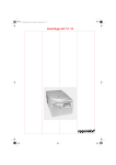
Figure 1 + 2
rpm
rcf
rad
short
prog
prog
accel
brake
rpm/rcf
min/sec
speed
time
open
start
stop
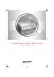
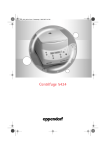
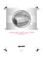
Fig. 1: Display field and control panel of the 5804 / 5810 (non-refrigerated)
rpm
rcf
rad
short
fast
temp
°C
temp
prog
prog
accel
brake
rpm/rcf
min/sec
speed
time
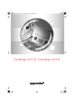
Fig. 2: Display field and control panel of the 5804 R / 5810 R (refrigerated)
3
open
start
stop
Titel_Rueck_Klapp.fm Seite 1 Dienstag, 13. Dezember 2005 8:51 08
Contents
Centrifuge 5804 / 5804 R / 5810 / 5810 R
Centrifuge 5804 / 5804 R / 5810 / 5810 R
Operating Instructions . . . . . . . . . . . . . . . . . . . . . . . . . . . . . . . . . . . . . . . . . . . . . . . . . . . . . . . . . . . . . . . . . . . . 5
Mode d’emploi succinct . . . . . . . . . . . . . . . . . . . . . . . . . . . . . . . . . . . . . . . . . . . . . . . . . . . . . . . . . . . . . . . . . . 26
Instrucciones breves. . . . . . . . . . . . . . . . . . . . . . . . . . . . . . . . . . . . . . . . . . . . . . . . . . . . . . . . . . . . . . . . . . . . . 32
No part of this publication may be reproduced without the prior permission of the copyright owner.
Copyright© 2005 Eppendorf AG, Hamburg
4
1B_5804_5810_US_en.fm Seite 5 Dienstag, 13. Dezember 2005 8:52 08
Centrifuge 5804 / 5804 R / 5810 / 5810 R
1
Contents
Introduction . . . . . . . . . . . . . . . . . . . . . . . . . . . . . . . . . . . . . . . . . . . . . . . . . . . . . . . . . . . . . . . . . . . . . . . . .
Delivery package. . . . . . . . . . . . . . . . . . . . . . . . . . . . . . . . . . . . . . . . . . . . . . . . . . . . . . . . . . . . . . . . . . . . . . .
Unpack . . . . . . . . . . . . . . . . . . . . . . . . . . . . . . . . . . . . . . . . . . . . . . . . . . . . . . . . . . . . . . . . . . . . . . . . . . . . . .
Installing the device . . . . . . . . . . . . . . . . . . . . . . . . . . . . . . . . . . . . . . . . . . . . . . . . . . . . . . . . . . . . . . . . . . . .
6
6
6
6
2
Safety regulations and applicational limitations . . . . . . . . . . . . . . . . . . . . . . . . . . . . . . . . . . . . . . . . . . . . 8
3
3.1
3.2
3.3
3.4
3.5
3.6
3.7
3.8
3.9
3.10
3.11
3.12
3.13
3.14
3.15
3.16
3.17
3.18
3.19
3.20
3.21
3.22
3.23
Operating . . . . . . . . . . . . . . . . . . . . . . . . . . . . . . . . . . . . . . . . . . . . . . . . . . . . . . . . . . . . . . . . . . . . . . . . . . 10
Operating controls . . . . . . . . . . . . . . . . . . . . . . . . . . . . . . . . . . . . . . . . . . . . . . . . . . . . . . . . . . . . . . . . . . . . . 10
Mounting / dismounting the rotors . . . . . . . . . . . . . . . . . . . . . . . . . . . . . . . . . . . . . . . . . . . . . . . . . . . . . . . . 10
Rotor lid F-45-30-11 . . . . . . . . . . . . . . . . . . . . . . . . . . . . . . . . . . . . . . . . . . . . . . . . . . . . . . . . . . . . . . . . . . . . 10
Loading the rotors. . . . . . . . . . . . . . . . . . . . . . . . . . . . . . . . . . . . . . . . . . . . . . . . . . . . . . . . . . . . . . . . . . . . . 10
Routine centrifugation with preset time / rcf display . . . . . . . . . . . . . . . . . . . . . . . . . . . . . . . . . . . . . . . . . . 12
Continuous operation . . . . . . . . . . . . . . . . . . . . . . . . . . . . . . . . . . . . . . . . . . . . . . . . . . . . . . . . . . . . . . . . . . 13
Short spin centrifugation (Short spin) . . . . . . . . . . . . . . . . . . . . . . . . . . . . . . . . . . . . . . . . . . . . . . . . . . . . . . 13
Time change during the run . . . . . . . . . . . . . . . . . . . . . . . . . . . . . . . . . . . . . . . . . . . . . . . . . . . . . . . . . . . . . 14
Refrigeration (for 5804 R/ 5810 R only). . . . . . . . . . . . . . . . . . . . . . . . . . . . . . . . . . . . . . . . . . . . . . . . . . . . . 14
Preset radius . . . . . . . . . . . . . . . . . . . . . . . . . . . . . . . . . . . . . . . . . . . . . . . . . . . . . . . . . . . . . . . . . . . . . . . . . 15
Centrifugation with Soft start / stop . . . . . . . . . . . . . . . . . . . . . . . . . . . . . . . . . . . . . . . . . . . . . . . . . . . . . . . 15
At set rpm . . . . . . . . . . . . . . . . . . . . . . . . . . . . . . . . . . . . . . . . . . . . . . . . . . . . . . . . . . . . . . . . . . . . . . . . . . . . 15
Preset program . . . . . . . . . . . . . . . . . . . . . . . . . . . . . . . . . . . . . . . . . . . . . . . . . . . . . . . . . . . . . . . . . . . . . . . 15
Programming . . . . . . . . . . . . . . . . . . . . . . . . . . . . . . . . . . . . . . . . . . . . . . . . . . . . . . . . . . . . . . . . . . . . . . . . 16
Write protection . . . . . . . . . . . . . . . . . . . . . . . . . . . . . . . . . . . . . . . . . . . . . . . . . . . . . . . . . . . . . . . . . . . . . . 16
Nominal value display . . . . . . . . . . . . . . . . . . . . . . . . . . . . . . . . . . . . . . . . . . . . . . . . . . . . . . . . . . . . . . . . . . 16
Automatic rotor recognition . . . . . . . . . . . . . . . . . . . . . . . . . . . . . . . . . . . . . . . . . . . . . . . . . . . . . . . . . . . . . 16
Display of elapsed spin time . . . . . . . . . . . . . . . . . . . . . . . . . . . . . . . . . . . . . . . . . . . . . . . . . . . . . . . . . . . . . 17
Switching on/off the warning signal . . . . . . . . . . . . . . . . . . . . . . . . . . . . . . . . . . . . . . . . . . . . . . . . . . . . . . . 17
Exiting the Service program . . . . . . . . . . . . . . . . . . . . . . . . . . . . . . . . . . . . . . . . . . . . . . . . . . . . . . . . . . . . . 17
Control via serial interface (optional). . . . . . . . . . . . . . . . . . . . . . . . . . . . . . . . . . . . . . . . . . . . . . . . . . . . . . . 17
Opening the centrifuge in the case of a power failure . . . . . . . . . . . . . . . . . . . . . . . . . . . . . . . . . . . . . . . . . . 17
Overload cutout switch / Fuses . . . . . . . . . . . . . . . . . . . . . . . . . . . . . . . . . . . . . . . . . . . . . . . . . . . . . . . . . . 17
4
4.1
4.2
4.3
4.4
4.5
4.6
4.7
Maintenance and cleaning . . . . . . . . . . . . . . . . . . . . . . . . . . . . . . . . . . . . . . . . . . . . . . . . . . . . . . . . . . . . 18
Device . . . . . . . . . . . . . . . . . . . . . . . . . . . . . . . . . . . . . . . . . . . . . . . . . . . . . . . . . . . . . . . . . . . . . . . . . . . . . . 18
The rotors . . . . . . . . . . . . . . . . . . . . . . . . . . . . . . . . . . . . . . . . . . . . . . . . . . . . . . . . . . . . . . . . . . . . . . . . . . . . 18
The aerosol-tight rotor . . . . . . . . . . . . . . . . . . . . . . . . . . . . . . . . . . . . . . . . . . . . . . . . . . . . . . . . . . . . . . . . . . 18
Rotor sterilization . . . . . . . . . . . . . . . . . . . . . . . . . . . . . . . . . . . . . . . . . . . . . . . . . . . . . . . . . . . . . . . . . . . . . . 18
Glass breakage . . . . . . . . . . . . . . . . . . . . . . . . . . . . . . . . . . . . . . . . . . . . . . . . . . . . . . . . . . . . . . . . . . . . . . . . 19
Refrigerated centrifuges . . . . . . . . . . . . . . . . . . . . . . . . . . . . . . . . . . . . . . . . . . . . . . . . . . . . . . . . . . . . . . . . . 19
Return of devices . . . . . . . . . . . . . . . . . . . . . . . . . . . . . . . . . . . . . . . . . . . . . . . . . . . . . . . . . . . . . . . . . . . . . . 19
5
Troubleshooting. . . . . . . . . . . . . . . . . . . . . . . . . . . . . . . . . . . . . . . . . . . . . . . . . . . . . . . . . . . . . . . . . . . . . . 20
6
Technical data . . . . . . . . . . . . . . . . . . . . . . . . . . . . . . . . . . . . . . . . . . . . . . . . . . . . . . . . . . . . . . . . . . . . . . 21
7
Ordering information . . . . . . . . . . . . . . . . . . . . . . . . . . . . . . . . . . . . . . . . . . . . . . . . . . . . . . . . . . . . . . . . . 22
Contents
1
1.1
1.2
1.3
5
1B_5804_5810_US_en.fm Seite 6 Dienstag, 13. Dezember 2005 8:52 08
1 Introduction
1
Introduction
The Centrifuges 5804 / 5810 are non-refrigerated bench-top centrifuges and the Centrifuges 5804 R / 5810 R are
refrigerated bench-top centrifuges. The 5804 / 5804 R models have a maximum capacity of 400 ml and the
5810 / 5810 R models have a maximum capacity of 1600 ml. All centrifuges are intended for use in research and
routine laboratories in the biosciences and in the fields of medicine and research.
This sign is found on your centrifuge and on several pages in the operating manual.
Texts labeled with this sign contain safety notes. Read these safety precautions before using the
centrifuge for the first time.
Before starting up the Centrifuges 5804 / 5810 and 5804 R / 5810 R for the first time, please read the instruction
manual.
1.1 Delivery package
1 Centrifuge 5804 / 5810 with fan cooling or 1 refrigerated Centrifuge 5804 R / 5810 R (rotor not included with
centrifuges)
1 Main power cable (European standard plug)
1 Instruction manual
1 Rotor key
1.2 Unpack
When the machines are removed from the packaging, they must be supported by two persons near the rubber feet at the
bottom on the left- and right-hand side and then carried the short distance to the lab bench. Please observe the weightbearing capacity of the bench. If the machines are to be transported over long distances in the lab, a trolley must be
used.
1.3 Installing the device
For 5804 R and 5810 R only: To avoid damage to the compressor caused by incorrect transportation,
wait four hours after installation before switching on the device.
To disconnect the centrifuge from the power supply in the event of an error, an emergency switch must be installed away
from the centrifuge, preferably outside the centrifugation room or next to the exit of this room.
6
–
Place the centrifuge onto a horizontal, stable and resonance-free work surface.
–
Ensure that the working environment is well-ventilated and not exposed to direct sunlight.
–
There should be 15 cm clearance at the sides of the centrifuge and 10 cm to the rear.
–
According to the regulations of the EN 61010-2-020 standard, a safety distance of 30 cm must be observed around
the centrifuge during operation. No objects which cause damage when destroyed must be positioned in this space.
–
Before plugging in the centrifuge, compare your power supply with the electrical requirements listed on the identification plate.
The mains cable of the centrifuge may be connected only to a socket with a protective conductor.
–
On refrigerated centrifuges 5804 R and 5810 R with a mains voltage of 120 V, a distinction is made between two
versions depending on requirements: the 15 A variant is equipped with a conventional IEC power cable (see Fig. 3) so
that these devices can be operated directly at the lab work-station using a conventional socket (120 V, 15 A).
However, this causes a drop in the cooling performance of this kind of device. This technical specification leads to a
rise in the lowest temperature which can be reached at maximum speed and to slower cooling down to the specified
value.
1B_5804_5810_US_en.fm Seite 7 Dienstag, 13. Dezember 2005 8:52 08
1 Introduction
1
Introduction
Fig. 3: 15 A IEC power cable
Fig. 4: 20 A standard variant
On the 20 A standard variant, by contrast, the power cable is permanently attached to the device (see Fig. 4). These
devices have a special 20 A plug and require the appropriate socket to guarantee the supply of current and voltage
required for the centrifuges (120 V, 20 A). The advantage is greater, more rapid cooling.
–
To switch on the centrifuge, press the mains switch (on the right-hand side of the device). The nominal values of the
test run appear in the display and the control lamp in the Open key lights up.
–
The centrifuge lid can be opened by pressing the Open key.
Please insert the rotor before starting and tighten it with the supplied rotor key.
The rotors A-4-81 and A-4-81-MTP are tightened with the special rotor key included in the rotor delivery package.
7
1B_5804_5810_US_en.fm Seite 8 Dienstag, 13. Dezember 2005 8:52 08
2 Safety regulations and applicational limitations
2
In the interests of your own personal safety, always observe the following regulations:
The rotor and the rotor cover must always be securely fastened.
Safety regulations and applicational limitations
Do not begin centrifugation before the rotor has been securely fastened.
The rotor must be loaded symmetrically. Opposing tubes should be of the same type and should be filled equally.
For reasons of mechanical stabilization, all positions of rotor A-4-44 and A-4-62 / A-4-62-MTP must be loaded with
buckets of the same type.
Prior to centrifugation, the tubes should in any case be visually inspected for material damage. Damaged tubes may not
be centrifuged. This is because broken tubes can, in addition to sample loss, result in further damage to the centrifuge
and accessories.
Do not use buckets and rotors which show clear signs of corrosion or mechanical defects. Please check accessories at
regular intervals.
Do not operate centrifuges which have not been correctly installed or repaired.
Do not move or knock against the centrifuge during operation.
Repairs must only be performed by an Eppendorf authorized service technician.
Only use original rotors and spare parts recommended by Eppendorf.
The Centrifuges 5804 / 5810 and 5804 R / 5810 R may only be used for special applications. They must not be operated
in a hazardous or flammable environment and must not be used to centrifuge explosive or highly reactive substances.
If such liquids are spilled in the rotor or rotor chamber, the centrifuge must be cleaned with a moist cloth and a mild soap
solution.
A liquid density of 1.2 g/ccm must not be exceeded at the maximum rotational speed.
During longer spin times in the 5804 / 5810 models, the sample tubes may heat up. Observe the limiting data specified
by the tube manufacturer.
The use of organic solvents (e.g. chloroform) may have an adverse effect on the stability of plastic test tubes.
Following operation in a cooling room, run the centrifuge for 30 minutes in the cooling room until it is warm. Alternatively,
allow it to warm up in a lab for at least three hours, but do not plug in the centrifuge in order to prevent damage caused
by condensation.
Rotors are high-grade components which are subject to extreme mechanical strain. Aluminium rotors are protected
against corrosion caused by commonly-used laboratory chemicals by means of an electrolytic coating, although this
protection cannot be fully guaranteed.
Please ensure that the rotor is protected from mechanical damage. Even slight scratches and cracks can cause severe
inner damage to the rotor materials, which are difficult or impossible to detect with the eye.
Please avoid using aggressive chemicals with the rotors. Such chemicals include concentrated and mild alkalis,
concentrated acids, solutions containing mercury ions, copper ions and other heavy-metal ions, chlorinated
hydrocarbons and concentrated saline solutions.
When handling toxic or radioactive liquids or pathogenic bacteria out of Risk Group II (see World Health Organization:
"Laboratory Biosafety Manual"), observe national regulations.
In the event of contamination caused by impurities or aggressive agents, the rotor must be cleaned immediately using a
neutral cleaning liquid. This is particularly important for the bores of the fixed-angle rotor and for the buckets.
Please clean your rotor regularly using a neutral cleaning liquid (e.g. Extran® neutral or RBS neutral). This will protect the
rotor and prolong its service life.
According to EN 55011, the centrifuges 5804/5804 R and 5810/5810 R are Class A products. Interference with
signal reception can occur in residential areas. The operator should take appropriate protective measures.
8
1B_5804_5810_US_en.fm Seite 9 Dienstag, 13. Dezember 2005 8:52 08
2 Safety regulations and applicational limitations
2
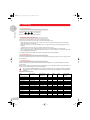
The following rotors and accompanying buckets have a maximum operating life of seven years. The date of production is
engraved on the rotor in four-digit form (e.g. 10/98 = October 1998):
5804 730.003
A-4-62-MTP
5810 711.002
A-2-DWP
5804 740.009
T-60-11
5804 730.003
F-34-6-38
5804 727.002
A-4-81
5810 718.007
A-4-62
5810 709.008
A-4-81-MTP
5810 725.003
Safety regulations and applicational limitations
A-4-44
12 1
98
11
5
6
2 3 4
8 9 10
Transparent rotor lids made of PC and PP as well as the PC caps of the rectangular buckets have an operating life of
three years. The date of production is engraved in the form of a clock
.
7
Contact with organic solvents (e.g. phenol, chloroform) may have an adverse effect on the transparent (polycarbonate)
caps of the aerosol-tight rotors. Please check lids of this type regularly for chemical damage or for cracks. Cracked caps
or caps with a milky discoloration must be replaced immediately.
Do not use rotors, caps or buckets which have been subjected to chemical or mechanical damage
or which have exceeded their maximum operating life!
* PC = Polycarbonate; PP = Polypropylene
9
1B_5804_5810_US_en.fm Seite 10 Dienstag, 13. Dezember 2005 8:52 08
3 Operating
3
3.1 Operating controls
Operating
See the fold-back cover at the front of this manual.
In the text,
prog
,
time
,
speed
, etc. signify keys
"Buckets" include buckets and titer plate buckets.
3.2 Mounting / dismounting the rotors
A summary of the various different rotors can be found in the brochure.
Clean the motor axle and the rotor bores with a cloth before attaching the rotor.
– When fastening / loosening the rotor onto / from the motor axle, ensure that the temperature of the rotor and the
motor axle is between 10 °C and 30 °C.
– Mount the rotor onto the motor axle and tighten the rotor nut by turning clockwise using the appropriate rotor key
supplied.
– To dismount the rotor, turn the rotor nut counterclockwise using the rotor key.
– When the rotors are not in the centrifuge, please place them in the rotor stand (Order no. 5804 720.008).
– Do not centrifuge using rotors and buckets with visible corrosion or mechanical defects (see Chapter 2: Safety regulations and applicational limitations ).
The Centrifuges 5804 / 5810 and 5804 R / 5810 R have automatic rotational speed limitation.
3.3 Rotor lid F-45-30-11
The non-aerosol-tight rotor lid of the rotor F-45-30-11 is attached by pressing the lid onto the rotor. The rotor lid need not
be screwed tight.
3.4 Loading the rotors
The rotors and buckets must always be loaded symmetrically. The adapters may only be loaded with the test tubes
recommended.
Differences in the weight of the filled sample tubes should be kept as low as possible in order to prolong the life-time of
the drive and to minimize running noises caused by imbalance.
On each rotor you will find information concerning the maximum weight of a completely loaded bucket (bucket
including adapter, tubes and liquid or titer plate buckets including titer plate and liquid) (see also applicational
limitations).
Performance data of the rotors
Type
Designation
max. capacity
(ml)
max. rotational
speed rpm /
max. rcf (x g)
max.
Radius
(cm)
5804 /
5804 R
5810 /
5810 R
Aerosol-tight
centrifugation
possible
A-4-81 1)
4 x 400 ml
4,000 / 3,250
18.0
–
●
●
A-4-81 1) 3)
96 x 2 ml
4,000 / 2,600
14.6
–
●
–
A-4-81-MTP 1)
16 x MTP-Platte
4,000 / 2,900
15.3
–
●
–
A-4-62 2)
4 x 250 ml
4,000 / 3,200
18.0
–
●
●
Swing-bucket rotors
A-4-62-MTP 2)
16 x MTP-Platte
4,000 / 2,750
15.4
–
●
–
A-4-44
4 x 100 ml
5,000 / 4,500
16.1
●
●
●
A-2-DWP
4 x Deepwell-Platte
3,700 / 2,250
14.7
●
●
–
Fixed-angle rotors
F-34-6-38
6 x 85 ml
11,000 / 15,550
11.5
●
●
–
F-34-6-38
6 x 85 ml
12,000 / 18,500
11.5
–
only 5810 R
–
F-45-30-11
30 x 2 ml
14,000 / 20,800
9.5
●
●
–
FA-45-30-11
30 x 2 ml
14,000 / 20,800
9.5
●
●
●
F-45-48-PCR
6 x 8er PCR-Streifen
12,000 / 15,350
9.5
●
●
–
60 x 2 ml
14,000 / 16,400
7.5
●
●
–
Drum rotor
T-60-11
10
1B_5804_5810_US_en.fm Seite 11 Dienstag, 13. Dezember 2005 8:52 08
3 Operating
3
Operating
1) The swing-bucket rotor can be delivered without buckets, equipped with rectangular buckets as an A-4-81 or with MTP buckets as an
A-4-81-MTP, whereby the flex buckets (especially MTP-buckets) can be purchased extra in sets of 2 or 4, user-friendly change of rectangular
buckets or MTP and flex buckets is guaranteed by the use of a common rotor cross.
2) The swing-bucket rotor can be delivered as A-4-62 (loaded with buckets) or as A-4-62-MTP (loaded with microtest plates). User-friendly
exchange of rectangular buckets or microtest plate buckets is guaranteed by the use of all-in-one rotor cross.
3) A-4-81 is equipped with flex buckets and IsoRack adapters.
Swing-bucket rotor
Only the combinations of rotor/buckets/adapter which are recommended by the manufacturer
may be used.
Please check whether all buckets have been inserted correctly and can swing freely.
For purposes of mechanical stabilization, all positions of the rotors A-4-44 and A4-62 / A-4-62-MTP must be loaded with
the same buckets. In contrast, the rotor A-4-81 / A-4-81-MTP can be equipped with a mix of rectangular buckets and
titer plate buckets. It is in principle not permitted to use swing-bucket rotors with only two rectangular buckets or titer
plate buckets inserted.
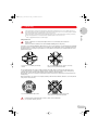
Fig. 5: Rotor A-4-81-MTP symmetrically
loaded
Fig. 6: Not allowed, because the pegs are not evenly
loades, rotor is asymmetrically loades
The rectangular buckets are sorted according to weight. The weight category is printed on the side in the groove:
e.g. 86 (the last two places in grammes). Opposing buckets should be of the same weight category. When placing
follow-up orders, please state the weight category. This also applies to titer plate buckets.
Ensure that the grooves are clean before inserting the buckets. Unclean grooves and pivots prevent the buckets from
swinging freely.
When working with a rotor which is not completely loaded, position the tubes within the buckets in such a way that the
rotor pivots are stressed evenly.
Fig. 7: Rotor is symmetrically loaded
Fig. 8: Not permitted: pivots are not stressed
evenly, rotor is not symmetrically loaded
A manual swing test with empty tubes must be carried out if oversized tubes
(i.e. longer than 100 mm) are used.
11
1B_5804_5810_US_en.fm Seite 12 Dienstag, 13. Dezember 2005 8:52 08
3 Operating
3
Operating
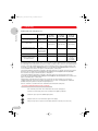
Permitted loads for the swing-bucket rotor
Rotor
A-4-44
(4 x 100 ml)
Maximum load per
100 ml rectangular bucket
310 g
(adapter + tubes)
Maximum load per
plate carrier
–––
Maximum load per 50 ml
Falcon® bucket
144 g
(for two conical
tubes incl. liquid
and form insert)
Specifications on the rotor
(weight for loaded buckets /
rectangular buckets)
4 x 0.6 kg
A-2-DWP
(Deepwellplate rotor)
A-4-62
(4 x 250 ml)
A-4-62-MTP
A-4-81
(4 x 400 ml)
A-4-81-MTP
–––
630 g
(adapter + tubes)
780 g
(adapter + tubes)
380 g
380 g
380 g
(with full plates)
(with full plates)
(with full plates)
–––
–––
–––
2 x 1.010 kg
4 x 1.1 kg
4 x 1.4 kg
(A-4-81)
4 x 1.22 kg
(A-4-81-MTP)
The weight specifications printed on the rotor (e.g. 4 x 0.6 kg for the 4 x 100 ml swing-bucket rotor A-4-44) correspond to
the overall weight of the rectangular bucket, inclusive of adapter, test tubes and the contents of each individual position.
In general, commercially-available deepwell plates with a 96-well plate format may only be used in the buckets of the
A-4-62-MTP on condition that the maximum load does not exceed 380 g and the maximum height of the plate does
not exceed 53 mm. This restriction also applies to stacked titer plates or culture plates.
Commercially available deepwell plates or filter plates / filter plate stacks in the 96-well plate format may be inserted in
the buckets of the A-2-DWP only if their load does not exceed 380 g and their height does not exceed 89 mm.
These restrictions also apply to stacked titer plates or culture plates.
Commercially available deepwell plates or filter plates / filter plate stacks may be inserted in the buckets of the
A-4-81-MTP only if their load does not exceed 380 g and their height does not exceed 60 mm. These restrictions also
apply to stacked titer plates or culture plates.
If deepwell plates used with dimensions which do not correspond to the values stated above (e.g. prototypes,
combination plates with a heavy lid or specially designed plates), the user must consult Eppendorf to establish the
suitability of using these plates in a titer plate or Deepwell plate rotor.
Under no circumstances use MTP-, MTP / Flex- and DWP-buckets with deformed side plates.
3.5 Routine centrifugation with preset time / rcf display
Turn on the main power switch. The nominal values of the last run are displayed.
Load the rotor symmetrically and close the centrifuge lid. The Open key lights blue.
speed
activates the preset speed. The SPEED display flashes.
modify the values. The new nominal value appears in the display.
If the preset speed is in rcf, please check the radius that has been entered. (see Section 3.10).
12
1B_5804_5810_US_en.fm Seite 13 Dienstag, 13. Dezember 2005 8:52 08
3 Operating
3
speed
to select rcf, press this key repeatedly until the rcf symbol ( ) appears to the left of the SPEED display.
The rcf value flashes and can be modified using the arrow keys.
activates the preset time. The TIME display flashes. The time can be modified using the arrow keys.
temp
activates the preset temperature. The nominal temperature in °C can be modified using the arrow keys.
start
stop
starts the run.
Operating
time
flashes and displays the rotation of the rotor.
Rotor recognition (see also Chapter 3.16) occurs at 200 to 700 1/min and the device then accelerates to the nominal
speed.
During the run, the rotational speed of the rotor or the appropriate rcf value, the sample temperature and the remaining
spin time in minutes are displayed. The last minute is counted down in seconds. During the run, all parameters can be
modified.
After the end of a run, or after a run has been interrupted by pressing the Stop key, the rotor is braked and brought to a
standstill. During the braking process, the time display flashes and the elapsed spin time is displayed.
When the lamp in the Open key lights up, the lid can be unlocked by pressing the key.
3.6 Continuous operation
time
The continuous operation function is set above 99 min or below 1 min using the arrow keys. In the time
display, "oo" indicates continuous operation.
During the run, the actual rotational speed/ RCF and temperature values and the elapsed time in minutes
are displayed. If the centrifuge runs for more than 99 min, "99." appears in the display. The run is ended
with the STOP key.
3.7 Short spin centrifugation (Short spin)
short
Press for as long as the run should last. The text "SH" will appear in the display. The elapsed time is
displayed in seconds. An already interrupted run can be continued up to two times by repeatedly pressing
the key, as long as the centrifuge has not yet come to a stillstand.
If the Short key is pressed while the lid is open, one of the following two status signs will appear, depending upon the
rotor recognized (see Chapter 3.16 Automatic rotor recognition): "rpm max" or "200 – rpm"
The status displays mean:
"rpm max":
The inserted rotor accelerates to its nominal rotational speed.
"200 – rpm":
The maximum rotational speed for the short-spin run can be set over the arrow keys.
If the Short key is pressed for longer than three seconds while the centrifuge lid is open, the device will switch over to the
other status and display it for two seconds. The status set last will be maintained.
13
1B_5804_5810_US_en.fm Seite 14 Dienstag, 13. Dezember 2005 8:52 08
3 Operating
3
3.8 Time change during the run
Operating
time
Press this key during the run (not during the braking phase).
change the duration of the run. The time elapsed is taken into
account in the new actual value.
3.9 Refrigeration (for 5804 R / 5810 R only)
temp
The nominal temperature value can be set from – 9 °C to + 40 °C.
It can be modified during centrifugation.
Once the nominal temperature value has been reached, a deviation greater than ± 3 °C is indicated by a
flashing temperature display.
If the temperature deviates by more than 5 °C, a periodic warning signal can be heard and the centrifuge
switches itself off.
fast
temp
starts a temperature run at a rotor-specific speed for the best possible refrigeration. The new preselected
temperature is quickly attained in the rotor by cooling. FT appears in the PROG field. The run is then
ended automatically at the arrived at nominal temperature or by pressing the Stop key. A signal can be
heard at regular intervals.
The centrifuge does not terminate the run until the rotor, carrier or rectangular bucket have reached the
pre-selected temperature. The target temperature is initially measured on the chamber and then shown in
the display. However, the temperature run is automatically terminated when the rotor, carrier or rectangular
bucket have reached the target temperature.
When the lid is closed, the rotor chamber is refrigerated to the preselected nominal temperature before or
Standbyrefrigeration after a run, as long as this value is below ambient temperature. The rotor does not turn during this
procedure and the temperature changes more slowly.
If the centrifuge is not used for longer than 8 hours, or if the lid is not opened for this time, the refrigeration
function switches off for safety reasons. Standby off appears in the display, together with the nominal
temperature in the rotor chamber. The desired temperature can be reached rapidly via the Fast Temp
function.
The standby cooling of the centrifuge can also be switched on permanently. To do this the Temp and Prog
keys must be pressed simultaneously. Standby 8h appears in the display. Following this, the Fast temp
must be pressed immediately in order to switch the standby cooling over into permanent operation.
Standby endless appears in the display.
The standby cooling is automatically switched off after 8 hours in order to protect the device.
The switching of standby cooling to permanent operation is carried out at own risk and can lead
to overheating of the compressor.
Please empty and clean the tray for condensation water (on the right at the bottom of the device) on a
regular basis.
Remove any condensation water and ice regularly from the rotor chamber using a soft, moist
cloth. Defrosting is recommended for ice removal.
14
1B_5804_5810_US_en.fm Seite 15 Dienstag, 13. Dezember 2005 8:52 08
3 Operating
3
3.10 Preset radius
speed
Operating
The internal conversion of rotational speed to RCF occurs as a standard with the largest radius
A smaller radius can be entered for another adapter.
Press this key repeatedly until the radius symbol ( ) appears to the left of the SPEED display.
The radius value flashes.
change the values entered. The new rcf value appears three seconds (or 10 s during the stillstand) after the
rotor radius has been entered.
3.11 Centrifugation with Soft start / stop
If the maximum acceleration / deceleration speed (level 9) is not desired, it is possible to set the speeds in nine different
levels.
time
Press this key repeatedly until
to the TIME display
(the symbol for the acceleration levels) appears next
Presetting the acceleration level 9 – 0.
Deceleration is set in the same way
.
Braking level 0 corresponds to free deceleration.
For levels 0 – 8, the symbols
appear in the display.
3.12 At set rpm
The "at set rpm" function triggers a counting down of the centrifugation time upon achieving the preselected rotational
speed ("at set rpm").
Pressing the START / STOP key for longer than 4 seconds while the centrifuge lid is open triggers a switching over to the
"at set rpm" function. While the key is pressed, both triangles of the pictogram are illuminated in blue in an alternating
sequence.
The activated "at set rpm" function is symbolized by the continuously illuminated, upper blue triangle
in the pictogram
.
In order to leave the "at set rpm" function again, and thus to activate the countdown of the centrifugation time directly
after switching on the centrifuge, press the START / STOP key while the centrifuge lid is open. The standard setting is
selected again after 4 seconds, symbolized by the illumination of the lower triangle in the pictogram
.
3.13 Preset program
Programs can only be preselected when the device is at a standstill.
prog
Press this key once ➔ the program no. that has been set flashes.
0
Data from last run.
1...9, A...Z Fixed programs.
select further program numbers.
start
stop
Returns to program 0 or leaves the programming mode when the lid is open.
In order to start the selected program immediately, the centrifuge lid must be closed prior to
pressing the START / STOP key.
15
1B_5804_5810_US_en.fm Seite 16 Dienstag, 13. Dezember 2005 8:52 08
3 Operating
3
3.14 Programming
Operating
Storing a fixed program (only possible when the device is at a standstill):
It is possible to save a maximum of 35 fixed programs (1...9, A...Z).
Enter the program data to be used first by pressing the parameter keys and the arrow keys or use the data from the last
run. The "at set rpm" functions and the set deceleration ramp can also be saved in a program if necessary.
prog
Press this key twice ➔ the first free program no., indicated by "P...", appears in the display and
flashes.
The desired free program number (1...9, A...Z) can be selected.
prog
Hold down this key for two seconds until ok appears in the display. The previously set parameters
of Temp., Speed, Time, etc. are now saved as a data set.
If parameters are modified during the run with a fixed program, "0" appears in the PROG field and the user exits the
program without it being modified.
To exit the fixed program, call up program "0" or modify the parameters.
3.15 Write protection
In order to avoid accidental deletion of an existing fixed program, the old data set must be deleted while the lid is open
prior to renewed assignment of a program number:
prog
Press this key once ➔ the program no. display flashes.
select the program no. which is to be deleted.
start
stop
Press this key within ten seconds until cleared appears.
3.16 Nominal value display
All nominal values are displayed when the centrifuge is at a standstill. During a run, all nominal values can be displayed
for 2.5 seconds by pressing one of the parameter keys (Temp, Speed, Time).
3.17 Automatic rotor recognition
Automatic rotor recognition occurs at the beginning of each run.
When a new rotor is recognized, the maximum rotational speed appears in the display for two seconds.
If the nominal speed set is greater than the maximum speed for the rotor used, it is aligned to the maximum speed and
the run is interrupted. SPEED appears in the display and the run must be restarted.
The rotational speed and the radius for the rcf value will be reset to the maximum permitted value.
If a run with a program has been started, the program number is set to "0".
16
1B_5804_5810_US_en.fm Seite 17 Dienstag, 13. Dezember 2005 8:52 08
3 Operating
3
3.18 Display of elapsed spin time
prog
If the Time key and the Prog key are pressed simultaneously, the total running time (in hours) of the
centrifuge appears in the display. This function can only be selected when the rotor is at a standstill.
Operating
time
3.19 Switching on/off the warning signal
speed
time
Press the Speed and Time keys simultaneously. "Alarm on" and "Alarm off" appear after 2 seconds
alternately in the display.
3.20 Exiting the Service program
If the Service program has been selected accidentally, press both arrow keys simultaneously.
3.21 Control via serial interface (optional)
All centrifuge functions can be operated via the serial interface (RS 232). The appropriate conversion must be carried out
by the service department.
Only devices which have been tested in accordance with IEC 950 may be connected via the serial interface.
3.22 Opening the centrifuge in the case of a power failure
If the magnetic lid latch cannot be activated because of a power failure, the emergency lid release can be activated
manually:
Turn off the main power switch. Wait until the rotor has come to a standstill (The rotor may continue spinning for
up to eight minutes). Insert the standard rotor key into the opening in the middle of the front part in the nut
underneath and turn counter-clockwise. This disengages the lid, allowing it to be opened.
Be absolutely sure to remove the rotor key afterwards.
3.23 Overload cutout switch / Fuses
The 230 V and 120 V devices have built-in thermal overload switches which function as all-pole fuses. When the
overload protection is actuated, these switches over the power switch to OFF, but do not switch it on again
automatically.
To turn on the overcurrent protector switch again, please turn off the centrifuge for 10 seconds with the mains power
switch. When the centrifuge is subsequently turned on again, the overcurrent protector switch will be automatically
reactivated.
17
1B_5804_5810_US_en.fm Seite 18 Dienstag, 13. Dezember 2005 8:52 08
4 Maintenance and cleaning
4
4.1 Device
Maintenance and cleaning
The outside of the centrifuge and the rotor chamber should be cleaned regularly with neutral
detergent. This is for hygiene purposes as well as to prevent contamination caused by residual
contamination.
The user is responsible for cleaning or decontaminating the centrifuge in the event of contamination caused
by high-risk substances.
Open the lid of the centrifuge and disconnect the main power plug. Unscrew the rotor with the rotor key provided and
clean separately. Only neutral agents may be used for cleaning and disinfection (e.g. diluted Extran® neutral, RBS
neutral or 70 % isopropanol/water mixture or an alcohol-based disinfectant). The rotor chamber should only be cleaned
with a moist cloth.
After cleaning with detergent, the rubber seals in the rotor chamber should be rinsed well with water and lubricated with
glycerine in order to prevent the seals from becoming brittle.
If condensation water forms in the rotor chamber after freezing occurs, dry with a soft absorbent cloth.
The user must consult the manufacturer before cleaning or decontaminating the centrifuge using methods not
recommended by the manufacturer in order to ensure that the centrifuge and accessories are not damaged. To ensure
that the centrifuge functions correctly and safely in the long-term, please note that aggressive chemicals can damage the
rotor, buckets and boiler. Please check the centrifuge regularly for damage caused by corrosion.
4.2 The rotors
The rotor and buckets must be cleaned regularly to prevent contamination caused by residue. Check at least the rotor
and housing monthly for residue and corrosion. This applies in particular to the rotor bores. Please clean your rotor using
a neutral cleaning liquid. This will protect the rotor and prolong its service life. As a reminder, the message "clean rotor"
appears in the display of the centrifuge three times after every 200 runs.
When using the swing-bucket rotor, ensure that the grooves in which the buckets are fitted are free of contamination. The
buckets can be lubricated with the lubricant (grease for pivots) supplied, although care must be taken to ensure that the
buckets can still swing freely.
4.3 The aerosol-tight rotor
The sealing rings of the aerosol-tight rotor FA-45-30-11 are subject to natural wear and tear and should be replaced
regularly if damaged. To protect the rotor, please ensure that the sealing rings are maintained regularly.
When handling the rotor lid, please observe the specifications regarding the chemical resistance of the materials of
construction.
The cover of the aerosol-tight rotor must not be fastened tightly during storage!
4.4 Rotor sterilization
All rotors are autoclavable (121 °C, 20 min).
After the rotor has been autoclaved ten times, the lids of the aerosol-tight buckets or rotors must be exchanged.
The aerosol-tight Rotor FA-45-30-11 and the lid can be autoclaved at 142 °C for 2 hours to destroy prions, but the
aerosol-tight lid must be exchanged after each autoclaving.
18
1B_5804_5810_US_en.fm Seite 19 Dienstag, 13. Dezember 2005 8:52 08
4 Maintenance and cleaning
4
4.5 Glass breakage
Maintenance and cleaning
When centrifuging glass tubes, please observe that high speeds/rcf’s increase the risk of glass breakage. Please follow
the manufacturer’s instructions concerning the maximum speed/rcf of centrifuge tubes. In the event of glass breakage,
carefully remove all splinters and all ground glass from the rotor, the buckets, the adapters and the rotor chamber. You
may need to replace the rubber mats and adapters to prevent further damage.
Fine splinters of glass may otherwise scratch the surface of the rotors and buckets, reducing their resistance to
chemicals. The air turbulences within the rotor chamber produce a very fine black powder of abraded metal. In addition
to causing damage to the rotor chamber, rotor, buckets and adapters, the powder also contaminates the samples.
Check the rotor bores regularly for residues and damage.
4.6 Refrigerated centrifuges
Clean the refrigeration mesh of the heat exchanger (on the rear side of the device) with a brush at least twice a year.
Be sure to first switch off the centrifuge and pull the plug.
Switch off the centrifuge after use, leave the lid open and empty the tray for condensation water, situated below the
device on the front right-hand side.
4.7 Return of devices
When returning centrifuges, please ensure that the devices have been decontaminated and thereby do not present a
health risk to our Service staff.
You will find additional information and a blank of the decontamination confirmation at www.eppendorf.com.
Do also consult your laboratory safety officer about a suitable decontamination method.
Please fill out the decontamination confirmation and place it together with the device when it is to be sent back to
Eppendorf.
19
1B_5804_5810_US_en.fm Seite 20 Dienstag, 13. Dezember 2005 8:52 08
5 Troubleshooting
5
Troubleshooting
Centrifuges 5804 / 5810 and 5804 R / 5810 R
Error
Display
Cause
Solution
No display.
None
No main power connection.
Check power supply cable.
Power failure.
Check main power fuse on the device and
in the laboratory.
clean rotor
Standby off
200 runs.
Centrifuge not used for 8 hours.
Clean rotor and drum.
Open lid and then close it again.
Centrifuge does not
start up.
no rotor
No rotor.
Error in the drive or rotor
recognition.
Mount rotor.
Switch off the device and switch it on
again.
Lid cannot be
opened.
None
Power failure.
Bring rotor to a standstill, activate
emergency lid release.
Lid not closed
completely.
Press Open
Close Lid
Lid latch not engaged.
Lid not closed correctly.
Press Open and close lid again.
Press down lid.
Lid does not open.
Lift Lid
Lid does not open automatically.
Open lid manually.
Centrifuge shakes
during acceleration
and switches off.
IMBAL
Rotor not loaded symmetrically.
Check rotor equipment and rotor load.
ROTOR
Rotor not fastened.
Fasten rotor correctly.
Device has been moved or work
surface unstable.
Place device on stable work surface.
SPEED
Nominal speed for rotor too high.
Enter new nominal speed.
Error 1
Rotor is not recognized.
Repeat run. If error recurs, test with
another rotor.
Centrifuge switches
off.
Problem with the rotational speed
measuring system.
Centrifuge switches
off. Warning signal.
Flashing
temperature display.
Error 2
Imbalance sensor damaged.
Error 3
Problem with the rotational speed Leave device switched on for 8 min, press
measuring system.
Open, then open the device. Repeat run.
Error 4
Lid latch sensor damaged.
Switch device off and then switch it on
again. Repeat run.
Error 5
Unauthorized opening of lid or lid
switch damaged.
Repeat run.
overload
or
Error 6
Converter overloaded.
Brake defective.
Voltage supply too low.
Rotor becomes loose.
Allow to cool. Restart device after 5 min.
Error 7
Overspeed.
Repeat run.
Error 8
Rotor loose.
Drive error.
Motor defective.
Tighten rotor.
overtemp
Temperature deviation from
nominal value > 5°C.
Repeat run.
Error 9–25
Electronics error.
Clear Memory
Program memory full.
Delete several programs or press Start or
Prog to begin new run.
Interrupt
Power failure during the run.
Restart.
Temperature deviation from
nominal value > 3 °C.
If the above solutions are unsuccessful, please contact SERVICE.
20
Repeat run.
Check voltage supply.
Tighten rotor.
1B_5804_5810_US_en.fm Seite 21 Dienstag, 13. Dezember 2005 8:52 08
6 Technical data
5804 / 5804 R
5810 / 5810 R
Power supply:
230 V / 50 or 60 Hz
230 V / 50 or 60 Hz
Maximum power requirement:
5804 / 5810
5804 R / 5810 R
900W
1650 W
900 W
1650 W
Fuse protection:
5804 / 5810
5804 R / 5810 R
Excess current switch 12 A
Excess current switch 12 A
Excess current switch 12 A
Excess current switch 12 A
Max. rotational speed:
14 000 rpm
14 000 rpm
Max. centrifugal force:
20 800 rcf
20 800 rcf
Max. kinetic energy:
5804 / 5810
5804 R / 5810 R
19 000 Nm (11 000 rpm)
19 000 Nm (11 000 rpm)
19 000 Nm (11 000 rpm)
23 000 Nm (12 000 rpm)
Max. load:
4 x 100 ml
4 x 400 ml
Max. density of material
to be centrifuged:
1.2 g/ml
1.2 g/ml
Permitted ambient temperature
during operation:
5804 / 5810
5804 R / 5810 R
2 °C to 40 °C
15 °C to 35 °C
2 °C to 40 °C
15 °C to 35 °C
Permitted maximum relative air humidity:
75 %
75 %
Degree of contamination
2
2
Overvoltage category
II
II
Standardized interface (optional)
RS 232 C
RS 232 C
Noise level
< 65 dB (A)
< 65 dB (A)
466 x 496 x 337 mm
(D = 550 with operating
section)
535 x 536 x 345 mm
(D = 608 with operating
section)
634 x 496 x 342 mm
(D = 550 with operating
section)
700 x 536 x 345 mm
(D = 608 with operating
section)
55 kg
80 kg
68 kg
99 kg
Power supply:
120 V / 60 Hz
120 V / 60 Hz
Maximum power requirement:
5804 / 5810
5804 R / 5810 R, 20 A version
5804 R / 5810 R, 15 A version
950 W
1650 W
1300 W
950 W
1650 W
1300 W
Fuse projection in the device:
5804 / 5810
5804 R / 5810 R, 20 A version
5804 R / 5810 R, 15 A version
Excess current switch 12 A
Excess current switch 18 A
Excess current switch 15 A
Excess current switch 12 A
Excess current switch 18 A
Excess current switch 15 A
Dimensions (W x D x H):
5804 / 5810
5804 R / 5810 R
Weight:
5804 / 5810
5804 R / 5810 R
6
Technical data
Centrifuges
Electrical data for 120 V model
Technical specifications subject to change!
21
1B_5804_5810_US_en.fm Seite 22 Dienstag, 13. Dezember 2005 8:52 08
7 Ordering information
7
Ordering information
Centrifuge 5804
Bench-top centrifuge, max. capacity 4 x 100 mL
with rotational speed regulation up to 14,000 rpm
120 V / 60 Hz, not including rotor
230 V / 50 – 60 Hz, not including rotor
Centrifuge 5804 R
Refrigerated bench-top centrifuge, max. capacity 4 x 100 mL
with rotational speed regulation up to 14,000 rpm
Temperature range: – 9 to 40 °C
120 V / 60 Hz, not including rotor
230 V / 50 – 60 Hz, not including rotor
Other voltages or 50 Hz frequency upon request.
22622501
22622552
22623508
22623559
Captain Eppi, Rotor key holder, 1 piece
Captain Eppi, Rotor key holder, 10 pieces
22639609
22639625
Rotor stand, for all rotors for Centrifuges 5804 5804 R / and 5810 / 5810 R
22639021
Swing-bucket rotor and accessories (see brochure for further details) for Centrifuge 5804 / 5804 R
Swing-bucket rotor A-4-44 (4 x 100 mL),
with 4 rectangular buckets of 100 mL
22637401
1 rectangular bucket of 100 mL with weight category (for individual deliveries,
please state the existing weight category)
22637410
2 aerosol-tight caps for 100 mL rectangular bucket
22637428
4 replacement seals for aerosol-tight caps of the rectangular bucket 100 mL
22637444
Adapters for standard test tubes, blood withdrawal systems and micro test tubes
for 100 mL rectangular bucket
(Number and diameter of bores)
2 adapters for
2 adapters for
2 adapters for
2 adapters for
2 adapters for
2 adapters for
2 adapters for
2 adapters for
2 adapters for
2 adapters for
3
1.5
4
3
7
7
12
30
50
80
–
5 mL test tubes (14 x 11)
–
2 mL micro test tubes (12 x 11)
–
7 mL test tubes (12 x 13)
– 15 mL test tubes (7 x 16)
– 17 mL test tubes (6 x 17.5)
– 18 mL test tubes (4 x 20)
– 30 mL test tubes (2 x 26)
– 50 mL test tubes (1 x 31)
– 75 mL test tubes (1 x 35)
– 120 mL test tubes (1 x 46)
4 spare rubber mats
2 spare clamps
22637509
22637525
22637541
22637568
22637584
22637622
22637649
22637681
22637703
22637720
22662503
22662511
Adapters for Falcon® test tubes for 100 mL rectangular bucket
(Number and diameter of bores)
22
2 adapters for 15 mL Falcon® test tubes (4 x 17.5)
2 adapters for 50 mL Falcon® test tubes (1 x 31)
22637606
22637665
4 buckets for 50 mL Falcon® test tubes (2 x 31)
8 spare adapters for 50 ml Falcon® tubes as re-order
22637452
22637479
Deepwell plate rotor A-2 DWP
with 2 DWP buckets for deepwell plates
22638564
Deepwell plate bucket with weight category for swing-bucket rotor A-2-DWP
(individual delivery only as a replacement delivery with prior agreement)
22638572
1B_5804_5810_US_en.fm Seite 23 Dienstag, 13. Dezember 2005 8:52 08
7 Ordering information
7
Fixed-angle rotors and accessories (see brochure) for the centrifuges 5804 / 5804 R 5810 / 5810 R
Fixed-angle rotor 6 x 85 mL, type F-34-6-38
with rotor lid
22637207
22662961
2 adapters for micro test tubes (4 x 11.5)
2 adapters for 7 – 15 mL test tubes (2 x 16.5)
2 adapters for 15 – 18 mL test tubes (1 x 18.5)
2 adapters for 20 – 30 mL test tubes (1 x 26.5)
2 adapters for 50 mL test tubes (1 x 29)
2 adapters for 50 mL Falcon® test tubes (1 x 29.5)
2 adapters for 15 mL Falcon® test tubes (1 x 17)
22637215
22637223
22637231
22637240
22637258
22637266
22637274
Fixed-angle rotor 30 x 1.5 mL, type F-45-30-11
with rotor lid
22637002
Spare lid for rotor F-45-30-11
22662970
Fixed-angle rotor 30 x 1.5 mL, type FA-45-30-11
aerosol-tight, with rotor lid of aluminium
22637100
Spare lid for rotor FA-45-30-11
22637126
6 adapters for 0.4 mL centrifuge tubes
6 adapters for 0.5 mL micro test tubes and Microtainers®
6 adapters for 0.2 mL PCR-tubes
22636243
22636227
22636260
PCR-strip rotor F-45-48-PCR for
6 x 8-strips, 6 x 5-strips, 48 x 0.2 mL PCR-tubes
22638581
Drum rotor and accessories (see brochure) for the centrifuges 5804 / 5804 R 5810 / 5810 R
Drum rotor T-60-11 with rotor lid,
for 60 x 1.5 mL / 2 mL tubes / 120 x 0.4 mL tubes
with 6 adapters for 1.5 mL /2 mL tubes
22638505
Adapter for 1.5 mL / 2 mL tubes (set of 6)
Adapter for 0.4 mL tubes (set of 6)
22638521
22638548
Accessories for the Centrifuges 5804 / 5804 R
Grease for pivots
Standard rotor key
Conversion kit for interface for 5804
Conversion kit for interface for 5804 R
Tray for condensation water
22634330
22664166
Upon request
Upon request
22662678
Ordering information
Spare lid for rotor F-34-6-38
Important note:
Please use the original accessories recommended by Eppendorf. Using spare parts or disposables which we have not
recommended can reduce the precision, accuracy and life of the centrifuges.
We do not honor any warranty or accept any responsibility for damage resulting from such action.
Rotor code
All Eppendorf rotors are designated
according to a simple, logical system
which describes the technical specifications as a uniform series of numbers
and letters e.g.:
Fixed-angle
rotor
F A
Aerosol-tight
version
Angle of
adapter bore
45
Ø Tube/
Adapter
30
Max. no. tubes/
adapters
11
Ø tube/adapter
bore
Swing-bucket rotor
A
4
81
Max. no tubes/
adapters
23
1B_5804_5810_US_en.fm Seite 24 Dienstag, 13. Dezember 2005 8:52 08
7 Ordering information
7
Ordering information
Centrifuge 5810
Bench-top centrifuge, max. capacity 4 x 400 mL
with rotational speed regulation up to 14,000 rpm
120 V / 60 Hz, not including rotor
230 V / 50 – 60 Hz, not including rotor
Centrifuge 5810 R
Refrigerated bench-top centrifuge, max. capacity 4 x 400 mL
with rotational speed regulation up to 14,000 rpm
Temperature range: –9 to 40 °C
120 V / 60 Hz, not including rotor
230 V / 50 – 60 Hz, not including rotor
Other voltages or 60 Hz frequency upon request.
Rotor stand, for all rotors for Centrifuges 5804 5804 R / and 5810 / 5810 R
22625004
22625055
22625501
22625551
22639021
Swing-bucket rotor and accessories (see brochure for further details) for Centrifuges 5810 / 5810 R
Swing-bucket rotor A-4-81 (4 x 400 mL) with 4 rectangular buckets of 400 mL
22638602
1 rectangular bucket of 400 mL with weight category
(for individual deliveries, please state the existing weight category)
22638637
2 aerosol-tight caps for 400 mL rectangular bucket
22638661
Replacement cap sealings
22638670
Adapters for standard test tubes, Vacutainers and Falcons® for
400 rectangular bucket:
24
2 adapters for 2.6 – 7 mL (25 x 13, number and diameter of bores)
2 adapters for 5 mL (Monovette®; 18 x 13)
2 adapters for 7 – 17 mL (16 x 17.5)
2 adapters for 5 mL Falcon® (12 x 7.5)
2 adapters for 50 mL Falcon® (5 x 31)
2 adapters for 180 - 250 mL tubes (1 x 62)
2 adapters for 400 mL (1 x 81)
2 adapters for Centriprep®‚ Centrifugal Filter Units (5 x 31)
22638700
22638718
22638726
22638742
22638769
22638921
22638785
22638904
Replacement adapter rubber mats
Replacement adapter clamps
22665201
22638696
2 bottles 400 mL
22638653
Swing-bucket rotor A-4-81-MTP, with 4 MTP / Flex-buckets
22638807
4 MTP / Flex-buckets for swing-bucket rotor type A-4-81-MTP or A-4-81 for use
of IsoRack adapters, cell culture flasks adapters and MTP, DWP
2 MTP / Flex-buckets
1 MTP / Flex-bucket
22638840
22638866
22638882
2 adapters for each cell culture flask for use in the MTP / Flex-buckets
2 adapters for each IsoRack for 0.5 ml micro test tubes
2 adapters for each IsoRack for 1.5 and 2.0 ml micro test tubes
22639005
22638980
22638998
1 IsoRack Starter Set: 2 IsoRack adapters, 2 IsoRacks with lid,
2 x 0 °C cool packs IsoRack; for 0.5 ml and 1.5 ml/2 ml micro test tubes
22510070
Swing-bucket rotor A-4-62 (4 x 250 mL), with 4 rectangular buckets of 250 mL
22638009
1 rectangular bucket of 250 mL with weight category
(for individual deliveries, please state the existing
weight category)
22638025
2 aerosol-tight caps for 250 mL rectangular bucket
22638033
4 replacement seals for aerosol-tight caps
22638017
1B_5804_5810_US_en.fm Seite 25 Dienstag, 13. Dezember 2005 8:52 08
7 Ordering information
7
Adapters for standard test tubes, blood withdrawal symptoms and micro test tubes
for 250 mL rectangular bucket (Number and diameter of bores)
1.5
1.5
4
3
7
7
18
30
50
80
160
–
5 mL test tubes (25 x 11)
–
2 mL micro test tubes (16 x 11)
–
7 mL test tubes (15 x 13)
– 15 mL test tubes (12 x 16)
– 17 mL test tubes (12 x 17.5)
– 18 mL test tubes (8 x 20)
– 30 mL test tubes (4 x 26)
– 50 mL test tubes (4 x 31)
– 75 mL test tubes (2 x 35)
– 120 mL test tubes (1 x 46)
– 250 mL test tubes (1 x 62)
4 spare rubber mats
4 spare rubber mats for adapter 22638441
2 spare clamps
22638203
22638220
22638246
22638262
22638301
22638327
22638360
22638386
22638408
22638424
22638441
Ordering information
2 adapters for
2 adapters for
2 adapters for
2 adapters for
2 adapters for
2 adapters for
2 adapters for
2 adapters for
2 adapters for
2 adapters for
2 adapters for
22638483
22638459
22628467
Adapters for Falcon® test tubes for 250 mL rectangular bucket
(Number and diameter of bores)
2 adapters for 15 mL Falcon® test tubes (9 x 17.5)
2 adapters for 50 mL Falcon® test tubes (3 x 31)
2 adapters for 50 mL Falcon®-test tubes (4 x 31)
22638289
22638343
22638351
Swing bucket rotor 4 x 100 mL, type A-4-44, see 5804 / 5804 R and brochure
Swing-bucket rotor A-4-62-MTP, with 4 plate carriers
22638041
4 plate carriers for swing-bucket rotor,
A-4-62-MTP, for 4 plates or 1 deepwell plate
22638068
1 plate carriers for swing-bucket rotor, A-4-62-MTP with weight category
(individual delivery only as a replacement delivery with prior agreement)
22638076
Deepwell plate rotor A-2 DWP with 2 DWP buckets for deepwell plates
22638564
Deepwell plate bucket with weight category for swing-bucket rotor A-2-DWP
(individual delivery only as a replacement delivery with prior agreement)
22638572
Fixed-angle rotors and accessories: see 5804 / 5804 R and brochure
Drum rotor and accessories: see 5804 / 5804 R and brochure
Accessories for the Centrifuges 5810 / 5810 R
Grease for pivots
Standard rotor key
Conversion kit for interface for 5810
Conversion kit for interface for 5810 R
Tray for condensation water
22634330
22664166
Upon request
Upon request
22662678
Important note:
Please use the original accessories recommended by Eppendorf. Using spare parts or disposables which we have not
recommended can reduce the precision, accuracy and life of the centrifuges.
We do not honor any warranty or accept any responsibility for damage resulting from such action.
25
Titel_Rueck_Klapp.fm Seite 4 Dienstag, 13. Dezember 2005 8:51 08
Eppendorf Offices
ASEAN
Eppendorf AG
Regional Office in Malaysia
Tel. +60 3 8023 2769
Fax +60 3 8023 3720
E-Mail: [email protected]
Internet: www.eppendorf.com.my
FRANCE
EPPENDORF FRANCE S.A.R.L.
Tel. +33 1 30 15 67 40
Fax +33 1 30 15 67 45
E-Mail: [email protected]
Internet: www.eppendorf.fr
GERMANY
SPAIN
Eppendorf Ibérica S.L.
Tel. +34 91 651 76 94
Fax +34 91 651 81 44
E-Mail: [email protected]
Internet: www.eppendorf.es
SWITZERLAND
AUSTRALIA / NEW ZEALAND
Eppendorf South Pacific Pty. Ltd.
Tel. +61 2 9889 5000
Fax +61 2 9889 5111
E-mail: [email protected]
Internet: www.eppendorf.com.au
Eppendorf Vertrieb
Deutschland GmbH
Tel. +49 2232 418-0
Fax +49 2232 418-155
E-Mail: [email protected]
Internet: www.eppendorf.de
Vaudaux-Eppendorf AG
Tel. +41 61 482 1414
Fax +41 61 482 1419
E-Mail: [email protected]
Internet: www.eppendorf.com
UNITED KINGDOM
AUSTRIA
Eppendorf AG
c/o Schott Austria
Tel. +43 1 29017560
Fax +43 1 290175620
E-Mail: [email protected]
Internet: www.eppendorf.com
INDIA
Eppendorf India Limited
Tel. +91 44 52111314
Fax +91 44 52187405
E-Mail: [email protected]
Internet: www.eppendorf.co.in
Eppendorf UK Limited
Tel. +44 1223 200 440
Fax +44 1223 200 441
E-Mail: [email protected]
Internet: www.eppendorf.co.uk
USA
ITALY
BRAZIL
Eppendorf do Brasil Ltda.
Tel. +55 11 30 95 93 44
Fax +55 11 30 95 93 40
E-Mail: [email protected]
Internet: www.eppendorf.com.br
Eppendorf s.r.l.
Tel. +390 2 55 404 1
Fax +390 2 58 013 438
E-Mail: [email protected]
Internet: www.eppendorf.it
Eppendorf North America
Tel. +1 516 334 7500
Fax +1 516 334 7506
E-Mail: [email protected]
Internet: www.eppendorfna.com
JAPAN
CANADA
Brinkmann Instruments, Ltd.
Tel. +1 905 826 5525
Fax +1 905 826 5424
E-Mail: [email protected]
Internet: www.brinkmann.com
Eppendorf Japan Co. Ltd.
Tel. +81 3 5825 2363
Fax +81 3 5825 2365
E-Mail: [email protected]
Internet: www.eppendorf.jp
NORDIC
CHINA
Eppendorf AG
Tel. +86 21 68760880
Fax +86 21 50815371
E-Mail: [email protected]
Internet: www.eppendorf.cn
Eppendorf Nordic Aps
Tel. +45 70 22 2970
Fax +45 45 76 7370
E-Mail: [email protected]
Internet: www.eppendorf.dk
OTHER COUNTRIES
see:
www.eppendorf.com/worldwide
In touch with life
Your local distributor: www.eppendorf.com/worldwide
Eppendorf AG · 22331 Hamburg · Germany · Tel. +49 40 538 01-0 · Fax +49 40 538 01-556 · E-Mail: [email protected]
Eppendorf North America, Inc. · One Cantiague Road, P.O. Box 1019 · Westbury, N.Y. 11590-0207 USA
Tel. +1 516 334 7500 · Toll free phone 800 645 3050 · Fax +1 516 334 7506 · E-Mail: [email protected]
Application Support
Europe, International: Tel. +49 1803 666 789 · E-Mail: [email protected]
North America: Tel. 800 645 3050 ext. 2258 · E-Mail: [email protected]
Asia, Pacific: Tel. +603 8023 2769 · E-Mail: [email protected]
eppendorf is a registered trademark.
B 5820 900.105-05/1205 · Printed in Germany · Printed on chlorine-free bleached paper
Titel_Rueck_Klapp.fm Seite 5 Dienstag, 13. Dezember 2005 8:51 08