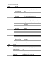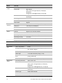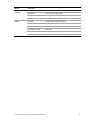
1
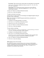
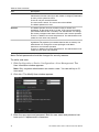
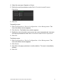
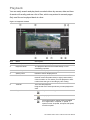
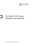
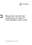
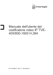
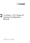
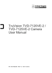
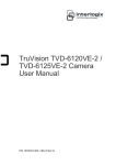
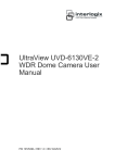
TVE-400/800-1600 H.264 IP Video Encoder User Manual P/N 1072585C-EN • REV 1.0 • ISS 16OCT12 Copyright Trademarks and patents Manufacturer Certification © 2012 UTC Fire & Security Americas Corporation, Inc. Interlogix is part of UTC Climate Controls & Security, a unit of United Technologies Corporation. All rights reserved. The Interlogix name and logo are trademarks of United Technologies. Other trade names used in this document may be trademarks or registered trademarks of the manufacturers or vendors of the respective products. UTC Fire & Security Americas Corporation, Inc. 2955 Red Hill Avenue, Costa Mesa, CA 92626-5923, USA Authorized EU manufacturing representative: UTC Fire & Security B.V. Kelvinstraat 7, 6003 DH Weert, The Netherlands N4131 FCC compliance Class B: This equipment has been tested and found to comply with the limits for a Class B digital device, pursuant to part 15 of the FCC Rules. These limits are designed to provide reasonable protection against harmful interference in a residential installation. This equipment generates, uses, and can radiate radio frequency energy and, if not installed and used in accordance with the instructions, may cause harmful interference to radio communications. There is no guarantee that interference will not occur in a particular installation. If this equipment does cause harmful interference to radio or television reception, which can be determined by turning the equipment off and on, the user is encouraged to try to correct the interference by one or more of the following measures: • Reorient or relocate the receiving antenna. • Increase the separation between the equipment and receiver. • Connect the equipment into an outlet on a circuit different from that to which the receiver is connected. • Consult the dealer or an experienced radio/TV technician for help. European Union directives 12004/108/EC (EMC directive): Hereby, UTC Fire & Security Americas Corporation, Inc., declares that this device is in compliance or with the essential requirements and other relevant provisions of Directive 2004/108/EC 2002/96/EC (WEEE directive): Products marked with this symbol cannot be disposed of as unsorted municipal waste in the European Union. For proper recycling, return this product to your local supplier upon the purchase of equivalent new equipment, or dispose of it at designated collection points. For more information see: www.recyclethis.info. 2006/66/EC (battery directive): This product contains a battery that cannot be disposed of as unsorted municipal waste in the European Union. See the product documentation for specific battery information. The battery is marked with this symbol, which may include lettering to indicate cadmium (Cd), lead (Pb), or mercury (Hg). For proper recycling, return the battery to your supplier or to a designated collection point. For more information see: www.recyclethis.info. Contact information For contact information, see www.utcfireandsecurity.com or www.utcfssecurityproducts.eu. Content Introduction 1 Package contents 1 Key features 1 Product description 2 Connections 3 Network Settings 5 TruVision Device Finder 5 Using a web browser 8 Before you start 8 Accessing the web browser 8 Menu tree 9 Live view 10 Description of live view 10 Capturing a snapshot 11 PTZ control 11 Video image settings 13 Configuration 14 Local configuration 14 Time settings 15 Network set up 16 Camera set up 21 Video streaming set up 22 Motion detection 23 Alarm input settings 27 Video loss 28 Tamper-proof alarm 29 System notification 30 Privacy masking 31 RS-485 settings 32 Scheduling record settings 32 Managing user accounts 35 Playback 38 Encoder management 40 Searching system logs 40 Restoring default settings 40 Viewing device information 41 Restarting the device 41 Importing/exporting parameters 41 Upgrading the system 42 TVE-400/800-1600 H.264 IP Video Encoder User Manual i Specifications 43 ii TVE-400/800-1600 H.264 IP Video Encoder User Manual Introduction The TruVision TVE H.264 IP video encoder converts the analog camera streams to compressed IP video streams. These streams are transited to network video recorders (NVR) or video management systems (VMS) for remote storage, liveview and playback purpose. This user manual provides basic information on setting up and using the TVE400, TVE-800 and TVE-1600 models. The encoder is shipped with on-screen display (OSD) menus in English only. Package contents The TruVision TVE H.264 IP video encoder is shipped with the following items: • TVE encoder • Power adaptor • Power cable • Quick start guide • CD (includes the user manual and TruVision Device Finder) Key features The following key features are supported by TVE encoders: • 4/8/16-channel H.264 encoding with dual stream output • Multiple resolution options: 4CIF, 2CIF, CIF and QCIF • Support audio & video compounded stream • Device configurable remote recording on Net HDD • Flexible and powerful recording mechanism: Scheduled, event triggered, alarm triggered, cycle recording, pre & post recording • Bi-directional audio • Local PTZ control via RS-485/422 port and burnt-in multiple PTZ protocols • 4 alarm in/1 alarm out • Support ONVIF, PSIA and CGI communication • Discoverable via the TruVision Discovery Tool TVE-400/800-1600 H.264 IP Video Encoder User Manual 1 Product description Figure 1: Front panel Encoder POWER Tx/Rx LED Description POWER The LED lights up green when the device is working. It is not lit when the device is powered down. TX/RX The LED is not lit when there is no network connection. It lights up green and flashes when data is being transmitted/received. It flashes at a faster rate when a large amount of data is being transmitted or received. Figure 2: Back panel 4-channel: 8-channel: 16-channel: Item Name Description 1. 12 VDC Connect a 12 V power supply via a PSU. 2. RS-485 Connect a PTZ camera or dome camera to the RS-485 serial port. 3. Alarm Out Connect up to one alarm relay outputs. 4. Alarm In Connect up to four alarm relay inputs. 2 TVE-400/800-1600 H.264 IP Video Encoder User Manual Item Name Description 5. LAN Connect the 10M/100Mbps self-adaptive UTP Ethernet port to a network. 6. Video In Connect up to 16 analog cameras (depending on model) to the BNC connectors. 7. Audio In Connect an audio input to the RCA connector. 8. Audio Out Connect an audio output the RCA connector. 9. GND Connect to ground. Connections See Figure 2 on page 2 for information on connecting the power, camera, audio and network cables. Alarm connections The TVE encoder supports the open/close relay input as the alarm input mode. When the alarm input signal not in open/close relay signal mode, please follow the connections shown below: Figure 3: Alarm input connections Alarm input connections for Emerson alarm: 100Ω 10 V regulator TVE 10 V regulator Emerson alarm ALM(+) V-output 14N34 optocoupler IN(n) ALM(-) G Relay input Alarm input connections for normal alarm: TVE JQC-3FG 24 V relay Alarm ALM(+) V-output ALM(-) IN(n) G TVE-400/800-1600 H.264 IP Video Encoder User Manual Relay input 3 1. Emerson alarm 4. 4N35 optocoupler 2. V output 5. Relay output 3. 10 V regulator 6. Normal alarm 7. JQC-3FG 24 V relay The TVE encoder supports the open/close relay input as the alarm output mode. The alarm input can be selected to NO or NC. Different alarm output connection methods are applied to the AC or DC load. See Figure 3. 4 TVE-400/800-1600 H.264 IP Video Encoder User Manual Network Settings This chapter explains how to use TruVision Device Finder to find and configure the IP address and other parameters of the device. Note: The default user name of TVE is admin, and password is 1234. The default IP address is 192.168.1.70 TruVision Device Finder The TruVision Device Finder tool can be found on the CD shipped with that product. This tool automatically identifies TruVision devices that support “autodiscovery” anywhere on the network, even in different subnets. You can view and modify the IP address of any discovered device. To install the TruVision Device Finder: 1. Insert the CD in the computer’s CD/DVD drive. 2. Browse to the folder IP Discovery Tool and double-click the Setup file located in the folder. 3. Click Next. 4. Select the folder where the setup will install the files then click Next. 5. The program requires a utility called WinPcap to be installed on the computer. If it is already installed, go to step 6. If the program is not installed, the WinPcap window appears. Follow the onscreen instructions. TVE-400/800-1600 H.264 IP Video Encoder User Manual 5 6. The TruVision Device Finder Wizard appears. Click Finish to complete its installation. Using the TruVision Device Finder The setup will install the necessary files and place the following shortcut on your desktop. Figure 4: TruVision Device Finder shortcut icon To use the TruVision Device Finder: 1. Double-click the shortcut icon to open the tool. The Start window appears. 2. Click Start to begin the discovery process. The list of TruVision devices located on your network appears. Note: The TruVision Device Finder can only detect devices that are on the same LAN. The tool cannot detect devices placed on a VLAN. 6 TVE-400/800-1600 H.264 IP Video Encoder User Manual The tool identifies: • Device type • Device MAC address • IP address • Number of video channels supported by the device • Connection port • Software version • Device serial number • DSP/firmware version • Device subnet mask 3. To change the IP address and/or the subnet mask of the device, click the line of the device address to be changed. The key device characteristics for that device are listed in the right pane. 4. Click Modify to change the IP address. The IP address and device port address fields will be available to change. 5. Change/modify the IP address and or subnet mask as required. Under Please Input Password, input the device’s logon password and press Save. 6. Repeat this process for each device that needs to be modified. When all changes to all discovered devices is complete, press Exit to close the tool. Note: You must reboot to activate the new IP address or subnet mask. TVE-400/800-1600 H.264 IP Video Encoder User Manual 7 Using a web browser You can configure the encoder over the network with a web browser. The supported web browsers include: • Internet Explorer 6/7/8/9 • Firefox 3.5 and above • Chrome 8 and above • Safari 5.0.2 and above Before you start • Before accessing the browser, you need to configure the network settings of encoder. • Connect the encoder to the LAN, and connect a computer to the same LAN as the encoder. • The encoder’s factory default user name is admin and the password is 1234. • The encoder’s factory default IP address is 192.168.1.70. Accessing the web browser To access the web browser: 1. Open the web browser and enter the IP address of the encoder (for example, http://192.168.1.70). Press the Enter key on the computer. The system displays the login window. 2. Enter the user name (default: admin) and password (default: 1234) to log into the system. The main page of the encoder appears. 3. If you need to install the TruVision Device Finder, click the center of the screen to start downloading it. The tool can be found on the CD shipped with the product. 8 TVE-400/800-1600 H.264 IP Video Encoder User Manual Menu tree Figure 5: Encoder menu tree TVE-400/800-1600 H.264 IP Video Encoder User Manual 9 Live view Live view mode is the normal operating mode of the device where you watch live images from the cameras. The encoder automatically enters into live mode once powered up. On the viewer, you can see the current date and time, camera name, and whether a recording is in progress. Description of live view Figure 6: Live view Item Name Description 1. Menu toolbar Lets you do the following: • View live video • Play back video • Search for event logs • Configure settings • Exit the interface 2. Viewer View live video. 3. Device list Display the encoder and its channels. 4. Display format 10 Define how you want video to be displayed in the viewer; single screen, 2X2, 3X3 or 4X4 (2X2 shown above). When in multiview mode, double-click on a video tile to get full-screen mode. Double-click again to return to multiview mode. TVE-400/800-1600 H.264 IP Video Encoder User Manual Item Name 5. Video function toolbar Description Click to start/stop live view. / Click to capture a snapshot of a video image. The image is saved on the computer. Click to manually start/stop recording video. / Click to display the previous camera view. Click to display the next camera view. Click to turn audio on/off. / 6. Video image Adjust the brightness, hue, saturation and contrast of live video. 7. Preset setup/selection Set up and select presets. 8. PTZ control panel Control PTZ of the currently selected camera, adjust the speed of PTZ movement and turn on/off the camera light and wiper. To see live view: 1. Open the encoder’s web browser screen. See Figure 6. 2. Double-click a camera from the device list to select a camera to view. 3. Click the Display Format button to view multiple video tiles. Capturing a snapshot In live view mode, click the snapshot button on the toolbar to capture the live pictures. A pop-up message will appear on screen to confirm that the capture was successful. The image is saved as a JPEG file on the computer. Note: Configure where the snapshots are saved on your computer in the Configuration > Local Configuration page. PTZ control You can control PTZ cameras from the encoder in live view mode. TVE-400/800-1600 H.264 IP Video Encoder User Manual 11 Figure 7: PTZ control Directional buttons: Control the pan and tilt movement Control the lens: Adjust the zoom in/out Adjust the focus near/far Adjust the iris open/close Adjust the speed of the pan and tilt movement Turn on/off the camera light and wiper Connecting the PTZ camera to the encoder Ensure that the PTZ dome cameras are correctly connected to the RS-485 port on the encoder back panel. Connect the R- and R+ terminals of the PTZ camera or speed dome to the RS-485 T- and RS-485 T+ terminals respectively. Configure the RS-485 parameters under the Configuration > Serial port settings > 485 serial port menu. See page 32. Presets Presets are previously defined locations of a PTZ dome camera. It allows you to quickly move the PTZ dome camera to a desired position. Up to 256 preset can be configured. To set up a preset: 1. In live view mode, select a preset from the preset list. 2. Use the directional, zoom, focus and iris buttons to position the camera in the desired preset location. 3. Click 12 to save the position. TVE-400/800-1600 H.264 IP Video Encoder User Manual To call up a preset: 1. In live view mode, select a camera. 2. Select a preset from the preset list. 3. Click . The camera immediately moves to that preset position. Video image settings You can manually adjust the brightness, saturation, contrast, and hue values of the camera image in order to get the best image quality. 1. In the live view window, click the Video Parameters button on the bottom right corner to display the Video Parameters Setting window: 2. Move the slider to adjust the brightness, contrast, saturation and hue. Note: The range of adjustment is 0 to 100. The default setting is 60. Click Default to restore the default settings. TVE-400/800-1600 H.264 IP Video Encoder User Manual 13 Configuration Local configuration Local configuration lets you define communication and network parameters such as protocol type, maximum file size, stream type and network transmission settings. You can also specify the directory locations for saving recorded and playback video, captured images, and downloaded files. To configure video loss detection: 1. Click Configuration > Local Configuration. The Local Configuration window appears. 2. Enter the required values. Protocol type: Set the protocol type of stream transmission to TCP or UDP. UDP provides more real-time audio and video streams. TCP ensures the complete deliver of streaming data and better video quality but it may not always be reliable for real-time delivery. Stream type: Select the stream type (main stream or sub stream) to be used for live view by the web browser. Window-division mode: Select the window-division view mode to 4:3, 16:9 or full-screen. Video file size: Select the size of packed video files during manual recording to 256M, 512M or 1G. Video stream buffering: Set the video buffering size to small (least latency), medium (balanced latency & fluency) or large (good fluency) to decrease latency or increase fluency for live view display performance. Save video file to: Set the saving path for the manually recorded video files. Save live pictures to: Set the saving path for the manually captured pictures in live view mode. Save playback picture to: Set the saving path for the captured pictures in playback mode. 14 TVE-400/800-1600 H.264 IP Video Encoder User Manual Save playback file to: Set the saving path for the clipped video files in playback mode. 3. Click Save to save the settings. Time settings You can set up the date and time that will appear on-screen and time stamped recordings. The start and end time of daylight savings time (DST) in the year can also be set. A Network Time Protocol (NTP) server can also be set up on your encoder to keep the date and time current and accurate. If the encoder is connected to a Dynamic Host Configuration Protocol (DHCP) network that has time server properties configured, the cameras will synchronize automatically with the time server. To configure time settings: 1. Click Device Configuration > Device Parameters > Time Settings. The Time Settings window appears. 2. Select the time zone. Select the time zone that is closest to the device’s location from the dropdown list. 3. Configure the time synchronization method: NTP server or manually. Configuring time sync by NTP server: Check the NTP box. Enter the IP address and port of the NTP server. Note: If the encoder is connected to a public network, you should use a NTP server that has a time synchronization function, such as the server at the National Time Center (IP Address: 210.72.145.44) or europe.ntp.pool.org. If the encoder is set up in a more customized network, NTP software can be used to establish a NTP server used for time synchronization. TVE-400/800-1600 H.264 IP Video Encoder User Manual 15 Configuring time synchronization manually: Check the Manual Time Sync box. Click the Select time icon to set the system time from the pop-up calendar. You can check the checkbox of Sync with local time to synchronize the time with the local PC. 4. Configure the DST settings, if required. Check the Enable DST box. Set the start time and end time of DST period. The end time must be later than the start time. When the DST period ends, the system reverts to the standard local time. Set the DST bias to 30 min, 60 min, 90 min or 120 min. 5. Click Save to save the settings. Network set up You must configure your encoder’s network settings before using it over the network. Table 1: Encoder network functions Function Description Basic settings Configure general network settings such as NIC type, IPv4 address, IPv4 subnet mask, IPv4 default gateway, MAC address and MTU. You can also configure the DNS server. PPPoE If the encoder is directly connected to ADSL modem, configure the PPPoE settings. Contact your ISP to get the user name and password. DDNS If the encoder is set up to use PPPoE as its default network connection, configure the Dynamic DNS (DDNS) to be used in conjunction. You need to register with your ISP before configuring your system for use with DDNS. E-mail Configure the encoder to send e-mail notifications of alarms or notifications through the network. Note: Ensure that the DNS address has been set up correctly beforehand. NetHDD Configure the network disk before operating the recording, playback or log searching. SNMP This is an internet-standard protocol for managing devices on IP networks. Configure this protocol to allow information on the encoder status as well as event and alarm notifications to be sent to a surveillance center. Before configuring this function, you must first install the SNMP software. To configure basic settings: 1. Click the Device Configuration > Network Settings > Basic Settings. The Basic Settings window appears. 16 TVE-400/800-1600 H.264 IP Video Encoder User Manual 2. Click General and enter the required settings: Option Description NIC type Network interface card (NIC) is a device used to connect the DVR to a network. Select the NIC type used from the drop-down list. Default value is 10/100/1000M self-adaptive. Enable DHCP Check this box if you have a DHCP server running and want your encoder to automatically obtain an IP address and other network settings from that server. Default value is Disable. IPv4 address Enter the IP address for the encoder. Default value is 192.168.1.70. IPv4 subnet mask Enter the subnet mask for your network so the encoder will be recognized within the network. Default value is 255.255.255.0. IPv4 default gateway Enter the IP address of your network gateway so the encoder will be recognized within the network. This is typically the IP address of your router. Default value is 0.0.0.0. MAC address Enter the MC address. MTU (bytes) Enter a value between 500 and 9676. Default is 1500. Preferred DNS server Enter the preferred domain name server to use with the encoder. Alternate DNS server Enter the alternate domain name server to use with the encoder. 3. Click Save to save the settings. To configure PPPoE settings: 1. Click the Device Configuration > Network Settings > PPPoE Settings. The PPPoE Settings window appears. 2. Check Enable PPPoE. TVE-400/800-1600 H.264 IP Video Encoder User Manual 17 3. Enter your user name and password and confirm the password. Note: The user name and password should be assigned by your ISP. 4. Click Save to save the settings. To set up DDNS: 1. Click the Device Configuration > Network Settings > DDNS Settings. The DDNS Settings window appears. 2. Check Enable DDNS. 3. Select one of the three DDNS types listed: • DynDNS: Enter the server address for DynDNS (i.e. members.dyndns.org). In the DVR Domain Name field, enter the domain obtained from the DynDNS web site. Then enter the user name and password registered in the DynDNS network. • IP server: Enter the server address for IPServer. • NO-IP: Enter the server address for NO-IP. In the domain name text field, enter the domain obtained from the NO-IP website (www.no-ip.com). Enter the user name and password registered on the NO-IP website. 4. Click Save to save the settings. To configure e-mail settings: 1. Click the Device Configuration > Network Settings > Basic Settings to set the IPv4 Address, IPv4 Subnet Mask, IPv4 Default Gateway and the Preferred DNS Server. 2. Click the Device Configuration > Network Settings > Email Settings. The Email Settings window appears. 3. Check Authentication if your mail server requires authentication. Enter the login user name and password. 4. Enter the required settings. 18 Option Description SMTP server Enter the SMTP server’s IP address. SMTP port Enter the SMTP port. The default TCP/IP port for SMTP is 25. Enable SSL Check the box to enable SSL if it is required by the SMTP server. This feature is optional. Interval The interval represents the time range in between the alarm images being sent. For example, if you set the interval at two seconds, the second alarm image will be sent two seconds after the first alarm image. Attached image Check the box if you want to send email with attached alarm JPEG images. Sender name Enter the name of the sender of the e-mail. Sender’s address Enter the sender’s e-mail address. TVE-400/800-1600 H.264 IP Video Encoder User Manual Option Description Choose receiver Select an e-mail recipient. Up to three receivers can be selected. Receiver Enter the name of the receiver of the e-mail. Receiver’s address Enter the e-mail address of the receiver. 5. Click Test to the test e-mail settings. Note: We recommend that you test the e-mail settings after entering values in the e-mail window. 6. Click Save to save the settings. To configure NetHDD settings: Note: Ensure that the network storage device is available within the network and is properly connected. Also the network storage device must be configured with NAS or IP SAN mode. 1. Click the Device Configuration > Network Settings > NetHDD Settings. The NetHDD Settings window appears. 2. Enter the IP address of the network storage system and file path in the text field. 3. Select the type of network storage system: IP SAN or NAS. NAS mode: Enter the IP address of the storage device. IP SAN mode: Enter the IP address of the storage device. 4. Click Save to add the configured network disk. 5. Initialize the added network disk. Click Device Configuration > HDD Management to enter the HDD settings menu. The capacity, free space, status, type and property of the added network disk are displayed. If the status of the network disk is Uninitialized, select the disk and click Init to start initializing it. When the initialization is complete, the disk status becomes Normal. TVE-400/800-1600 H.264 IP Video Encoder User Manual 19 Note: Up to 8 NAS or IP SAN disk can be connected to the encoder. 6. Set the property of the added network disk. Select the HDD number. Select its property from the drop-down menu: R/W, Read-only or Redundancy. Note: Please refer to the IP SAN/NAS user manual on how to create a file path in network management. To configure SNMP protocol settings: 1. Click the Device Configuration > Network Settings > SNMP Settings. The SNMP Settings window appears. 2. Enter the NIC port value. The default value is 161. 3. When SNMPv1 and/or SNMP v2c are enabled, you can configure the read SNMP community (default: public), write SNMP community (default: private), tap address (default: empty) and trap port (default: 162). 4. When SNMPv3 is enabled, you can configure the read user name (default: public). Note: SNMPv1, SNMP v2c and SNMPv3 are disabled by default. 5. Select the security level: “no auth, no priv”, “auth, no priv” or “auth, priv”. 6. When the security level is set to “auth, priv”, configure the Authentication Algorithm and Privacy Algorithm parameters. 20 TVE-400/800-1600 H.264 IP Video Encoder User Manual When the security level is set to “no auth, no priv”, the Authentication Algorithm and Privacy Algorithm parameters cannot be configured. 6. Click Save to save the settings. Camera set up You can configure which information is displayed on-screen. The on-screen display (OSD) settings appear in live view and recording modes and include the camera name, time and date. You can also adjust the transparency of the OSD relative to the background so that it is easier to read or is less prominent on screen. You can add up to eight lines of text on screen. This option can be used, for example, to display emergency contact details. To configure the OSD settings: 1. Click the Device Configuration > Camera Settings > Display Settings. The Display Setting window appears. 2. Select a camera from the drop-down list. 3. Enter a camera name in the text field. 4. Check the Display Name, Display Date, and Display Week boxes to display the camera name, date, and week. 5. Select a date format and a time format. 6. Select how you want the camera information displayed. Select one of the options from the drop-down list. Default is nontransparent/non-flashing. • • • • Transparent & flashing Transparent & not flashing Non-transparent & flashing Non-transparent & non-flashing TVE-400/800-1600 H.264 IP Video Encoder User Manual 21 7. There are two red text boxes in the camera view screen; one for the camera name and the other for the date/time. Using the mouse, click and drag a text box to the desired position. 8. To copy the settings to other cameras, click Copy to Camera and select the desired cameras. Click OK. 9. Click Save to save the settings. To add a text overlay: 1. Click the Device Configuration > Camera Settings > Text Overlay Settings. The Text Overlay Setting window appears. 2. Select a camera from the drop-down list. 3. Click the checkbox for a line of text and enter the characters. The text box appears on the camera view screen. Using the mouse, click and drag the text box to the desired position. . 4. Click Save to save the settings. Video streaming set up You can adjust the video recording parameters to obtain the image quality and file size best suited to your needs. To configure video settings: 1. Click Device Configuration > Camera Settings > Video Settings. The Video Setting window appears. 22 TVE-400/800-1600 H.264 IP Video Encoder User Manual 2. Select a camera from the drop-down list. 3. Select the dual streaming method to be used: Main stream (Normal), Substream, and Main stream (Event). Default is Main stream (Normal). Note: Main stream is usually used for recording and live viewing with good bandwidth. Substream is used for live viewing when the bandwidth is low. 4. Specify the parameters of the main stream or substream: Stream type: Select Video to record video stream only or Video&Audio to record both video and audio streams. Default is Video&Audio. Resolution: Select the recording resolution: NTSC values are 704x480, 704x240, 352x240, or 176 x120 for NTSC. PAL values are 704x576, 704x288, 352x288, or 176 x 144. Bit rate type: Select variable or fixed bit rate. Variable produces higher quality results suitable for video downloads and streaming. Default is Variable. Image quality: This option is available when the bit rate type is variable. Select one of the options: Highest, Higher, Medium, Low, Lower, or Lowest. Default is Highest. Frame rate: Select one of the options: 1, 2, 4, 6, 8, 10, 12, 15, 16, 18, 20, 22 or full frame 25/30 (PAL/NTSC). Default is full frame (25/30 (PAL/NTSC)). Max bit rate: Enter the maximum allowed bit rate. Value must be between 32 and 3072 Kbps. Video encoding: Select the video encoding standard H.264. 5. Click Save to save the settings. Motion detection The encoder can be set up to trigger an alarm if it detects motion and to record it. You can then search these recorded motion activities for specific incidents. TVE-400/800-1600 H.264 IP Video Encoder User Manual 23 Select the level of sensitivity to motion so that only objects that could be of interest can trigger a motion recording. For example, recording is triggered by the movement of a person but not that of a cat. To configure motion detection: 1. Click Configuration > Camera Settings > Motion detection. The Motion Detection window appears. 2. Select a camera from the drop-down list. Each camera must be set up individually. 3. Check Enable Motion Detection. 4. Select the area sensitive to motion and the sensitivity level. Click Start Draw. Click and drag the mouse cursor across the screen. The area selected appears as a red grid. Areas covered by the red grid are sensitive to motion detection. Up to eight areas can be drawn. Click Stop Draw when completed. Click Clear All to clear the screen. Drag the Sensitivity scroll bar to the desired sensitivity level. The highest value is on the right of the bar. Click Save to save the settings. 5. Select the recording schedules for motion detection. Click the Arming schedule tab. Click Edit. 24 TVE-400/800-1600 H.264 IP Video Encoder User Manual Select the day of the week when motion can be recorded. Click to set the time periods for the arming schedule during the day. You can schedule up to eight time periods in a day. Default is 24 hours. Click OK. Note: Time periods defined cannot overlap. 6. Select the response method to motion detection. Click the Linking Method tab. TVE-400/800-1600 H.264 IP Video Encoder User Manual 25 Under Alarm Linking check one of more of the desired the response methods: - Audible warning: Trigger an audible beep when an alarm is detected - Notify surveillance center: Send a notification or alarm signal to remote alarm host when an event occurs. The alarm host refers to the computer installed with remote client software - Send e-mail: Send an e-mail with alarm information to a user or users when an event occurs. Under Trigger Alarm Output select the channel to trigger an external alarm output when a motion detection event occurs. See “To set up an alarm output” below on how to set up an external alarm output. Select the channel to trigger recording when a motion detection event occurs. 7. Click Save to save settings. To configure an alarm output: 1. Click Device Configuration > Alarm Settings > Alarm Output. The Alarm Output window appears. 2. Select an alarm output. 3. Select a time out option. The time out setting lets you define how long a signal remains active after the alarm has ended. Select a time out option: 5, 10, and 30 seconds, 1, 2, 5, and 10 minutes, and Manual clear. If “Manual clear” is selected, the alarm output will stop only when the alarm input stops. 26 TVE-400/800-1600 H.264 IP Video Encoder User Manual If you select Manual Trigger, the signal remains active until it is manually acknowledged by selecting “No”. 4. Select the recording schedules for the alarm output. Click Edit. In the Edit Schedule Time window select the day of the week and the time periods during the day when motion can be recorded. You can schedule up to eight time periods in a day. Default is 24 hours. Click Save to save the settings. Note: The time periods defined cannot overlap. 5. Click Save to save settings. Alarm input settings The encoder can be configured to record when an alarm is triggered by an external alarm device (for example, PIR detector, dry contacts…). To configure alarm inputs: 1. Click Device Configuration > Alarm Settings > Alarm Input. The Alarm Input window appears. 2. Select the alarm input number of a camera. 3. Select the alarm input type, NO or NC. 4. Set the arming schedule for the alarm input. 5. Select the response method to motion detection. Click the Linking Method tab. Under Alarm Linking check one or more of the desired the response methods: - Audible warning: Trigger an audible beep when an alarm is detected - Notify surveillance center: Send a notification or alarm signal to remote alarm host when an event occurs. The alarm host refers to the computer installed with remote client software TVE-400/800-1600 H.264 IP Video Encoder User Manual 27 - Send e-mail: Send an e-mail with alarm information to a user or users when an event occurs. Under Trigger Alarm Output select the channel to trigger an external alarm output when a motion detection event occurs. See “To set up an alarm output” on how to set up an external alarm output. Select the channel to trigger recording when a motion detection event occurs. If the camera is PTZ, select PTZ linking. 6. Click Save to save settings. Video loss Video may be lost if the video cable or camera develop a fault or are damaged. You can set up your encoder to detect video loss and trigger a system notification. To configure video loss detection: 1. Click Device Configuration > Camera Settings > Video Loss. The Video Loss window appears. 28 TVE-400/800-1600 H.264 IP Video Encoder User Manual 2. Select a camera to configure for video loss detection. 3. Check the Enable Video Loss box. 4. Under the Arming Schedule tab, click Edit to modify the arming schedule for video loss detection. The configuration is the same as that for the arming schedule for motion detection. See page 23 for further information. 5. Select the Linking Method tab. Then select the response method to notify you of the alarm. 6. Click Save to save the settings. Tamper-proof alarm Video tampering, such as moving a camera to a different position, can also be detected and set to trigger an action on the encoder. Note: It is strongly recommended not to configure for video tampering when using PTZ dome cameras. To configure tamper-proof detection: 1. Click Device Configuration > Camera Settings > Tamper-Proof. The Tamper-Proof Settings window appears. TVE-400/800-1600 H.264 IP Video Encoder User Manual 29 2. Select camera for which to set up tamper-proof detection. 3. Check the Tamper-Proof box. Note: Under Area Settings, the full screen is set for tamper-proof detection. This cannot be changed. 4. Select the Arming Schedule tab and click Edit to modify the arming schedule for video loss detection. The configuration is the same as that for the arming schedule for motion detection. See page 23 for further information. 5. Select the Linking Method tab. Then select the response method to notify you of the alarm. 6. Click Save to save the settings. System notification Setting up system notifications instructs the encoder to alert you when irregular events occur and how to alert you to the event. The system notifications include: • HDD full: All installed HDDs are full. • HDD error: Errors occurred while files were being written to the HDD, no HDD installed or HDD had failed to initialize. • Network disconnected: Disconnected network cable. • IP conflicted: Conflict with IP address setting. • Illegal login: Wrong user ID or password used. • Abnormal record: No space on the HDD to save recorded files. • Abnormal video signal: Poor video quality. To set up system notifications: 1. Click Device Configuration > Notification. The Notification window appears. 30 TVE-400/800-1600 H.264 IP Video Encoder User Manual 2. Select a notification type. 3. Check one or more response options: Audible warning, notify surveillance center, send e-mail, and trigger alarm output. 4. Click Save to save the settings. Privacy masking You can define an area on screen to remain hidden from view. For example, you can choose to block the view of a camera when overlooking residential premises. This hidden area is referred to as privacy masking. Privacy masking cannot be viewed in live view or recorded mode, and appears as a blank area on the video image. To configure a privacy mask: 1. Click Device Configuration > Camera Settings > Privacy Mask. The Privacy Mask window appears. 2. Select camera for which to set up privacy masking. 3. Check the Enable Privacy Mask box. TVE-400/800-1600 H.264 IP Video Encoder User Manual 31 4. Click the Start Draw buton to start drawing an area. 5. Using the mouse, click and drag a privacy-mask box in the camera view screen over the desired area. You can set up to four areas for privacy masking. 6. Click the Stop Draw button to stop drawing. Note: Click the Clear All button to clear all mask areas. 7. Click Save to save the settings. RS-485 settings The RS-485 serial port is used to control the PTZ of the camera. The PTZ parameters need to be configured before you control the PTZ unit. To configure a privacy mask: 1. Click Device Configuration > Serial Port Settings > RS-485. The RS-485 window appears. 2. Enter the RS-485 parameters. The default parameters are: Baud rate: 9600 Data bit: 8 Stop bit: 1 Parity: None Flow control: None PTZ protocol: A-01 Address: 0 Note: It is important to ensure that the settings correspond with those used in the PTZ camera. 3. Click Save to save the settings. Scheduling record settings Ensure that the NetHDD has been installed and initialized before configuring the recording settings. Description of the record schedule window Defining a recording schedule lets you specify when the encoder records video and under what circumstances. Each camera can be configured to have its own recording schedule. 32 TVE-400/800-1600 H.264 IP Video Encoder User Manual Figure 8: Description of the Record Schedule window 1. Schedule time. Represents the 24-hour cycle during which a schedule is selected. 2. Camera. Select a camera for the recording schedule. 3. Recording type. There are five recording types to select for the schedule, which are colorcoded: Normal (Blue): Records continuously. Motion (Green): Records only motion events. Alarm (Red): Records only alarm events. Motion | Alarm (Orange): Records motion or alarm events. Motion & Alarm (Pale blue): Records motion and alarm events. 4. Timeline (TL). There is a 24-hour time line for each day. Each square in the timeline represents an hour in the 24-hour period. Up to eight recording periods can be scheduled during the 24-hour period. TVE-400/800-1600 H.264 IP Video Encoder User Manual 33 To configure a scheduled recording: 1. Click Device Configuration > Camera Settings > Record Schedule. The Record Schedule window appears. 2. Select the camera you want to configure. 3. Check the Enable Schedule box. If left unchecked, the encoder will not record. 4. Click Edit to configure the recording settings. 5. Configure the recording schedule: All day recording: Check All Day. Segment recording: Check Segment Record. Check the day of the week required and set the start and end time for recording. You can schedule up to eight time periods in a day. The segments cannot overlap. 6. Select a recording type. This setting instructs the encoder to begin recording when an alarm is triggered. The recording types available are: Normal, Motion, Alarm, Motion or Alarm, Motion and Alarm. Note: If Motion, Alarm, Motion or Alarm, Motion and Alarm types are selected, you must also configure the alarm linking method to be used. See “Motion detection on page 23 and “Alarm input settings” on page 27. 7. Copy the schedule to other days of the week. Check Select All to copy the schedule to all days of the week. To copy these settings to another day, check the days required and click Copy. Note: To configure different schedules for other days, click the tab for the desired day and set the schedule. 8. Click OK to save the settings. Return to the Record Schedule window. 9. Schedule pre and post recording times. Click Advanced and select the desired times. 34 TVE-400/800-1600 H.264 IP Video Encoder User Manual Pre-record: This is the time the camera starts recording before the scheduled time or event. The times available are: No pre-record, 5 s, 10 s, 15 s, 20 s, 25 s, 30 s or Unlimited. Post-record: This is the time the camera continues to record after the scheduled time or event. The times available are: 5 s, 10 s, 30 s, 1 min, 2 min, 5 min or 10 min. 10. Click OK. Return to the Record Schedule window. 11. Click Save to save the settings. To make redundant recordings: Use this option to make a back-up of recordings as a safeguard against losing all the files in case of disk failure. Note: You must have one NetHDD property identified as redundant to do redundant recording. 1. Configure the recording schedule of a camera. 2. Click Advanced in the Record Schedule window. 3. Under Redundant Record select the Yes. 4. Click OK. Return to the Record Schedule window. 5. Click Save to save the settings. To auto delete recordings: 1. Click Configuration > Device Configuration > Camera Settings > Record Schedule. The Record Schedule window appears. 2. Configure the recording schedule of a camera. 3. Click Advanced in the Record Schedule window. Under Expired Time select the number of days after which recorded video from the specified camera is permanently deleted from the HDD. 4. Click OK. Return to the Record Schedule window. 5. Click Save to save the settings. Managing user accounts By default the encoder comes with three user accounts: an Administrator account, an Operator account and a Guest account. These accounts provide multiple levels of access and functionality. See Table 2 on page 36 for a description of the different user accounts. TVE-400/800-1600 H.264 IP Video Encoder User Manual 35 Table 2: User accounts User Description Administrator The administrator account includes full access to all settings. The Administrator has the authority to add, delete or configure parameters for many of the system functions. There can only be one administrator. The user name is admin. The name cannot be modified. The default password is 1234. Operator The default operator account includes access to remote view logs/status, bi-directional audio, live view, PTZ control and playback (inaccessible features are not visible). The administrator can change the access privileges under Basic Permission and Camera Operation. There is no default user name and password. The administrator must create the user name and password. Guest The default guest user account includes access to remote view logs/status and playback (inaccessible features are not visible). The administrator can change the access privileges under Basic Permission and Camera Operation. There is no default user name and password. The administrator must create the user name and password. Note: Default passwords should be changed for security reasons. To add a new user: 1. Click Configuration > Device Configuration > User Management. The User Information window appears. Note: Only a system administrator can create a user. You can add up to 31 new users. 2. Click Add. The Modify User window appears. 3. Enter the user name and password. Both the user name and password can have up to 16 alphanumeric characters. 36 TVE-400/800-1600 H.264 IP Video Encoder User Manual 4. Select the user type: Operator or Guest. 5. Define the user’s permissions under Basic Permission and Camera Operation. 6. Click OK. To modify a user: 1. Click Configuration > Device Configuration > User Management. The User Information window appears. 2. Click Modify. The Modify User window appears. 3. Modify the user information such as the user name and password, user type, and user’s permissions under Basic Permission and Camera Operation. 4. Click OK. To delete a user: 1. Click Configuration > Device Configuration > User Management. The User Information window appears. 2. Click Delete. 3. Click OK in the pop-up window to confirm deletion. The user is immediately deleted. 4. Click OK. TVE-400/800-1600 H.264 IP Video Encoder User Manual 37 Playback You can easily search and play back recorded videos by camera, date and time. A search will usually produce a list of files, which may extend to several pages. Only one file can be played back at a time. Figure 9: Playback window Item Name Description 1. Camera panel Select the cameras for playback. 2. Playback viewer The playback video has a time/date stamp on it for evidentiary purposes. 3. Calendar panel Select a date to playback recordings. 4. Search panel Results of search displayed here. 5. Timeline Allows you to jump forwards or backwards in time. The timeline moves left (oldest video) to right (newest video). Click a location on it for where you want playback to start. It also shows the type of recording by color coding. 6. Time bar Time of actual playback. Drag the bar to an exact spot where you want playback to start. 7. Playback control toolbar Play back recording. Stop playback. Decrease playback speed: Options available are: single frame, 1/8 speed, ¼ speed, ½ speed, normal, X2 speed, X4 speed, X8 speed, maximum speed. 38 TVE-400/800-1600 H.264 IP Video Encoder User Manual Item Name Description Increase playback speed. Options available are: single frame, 1/8 speed, ¼ speed, ½ speed, normal, X2 speed, X4 speed, X8 speed, maximum speed. Play back frame-by-frame. This allows you to carefully examine an event frame-by-frame as it happens Stop playback for all cameras. Capture a snapshot of a video image. The image is saved on the computer. / Start/stop video clip during playback. Sections of a recording can be saved to an external storage device. Audio on/off. / 8. Recording type Description of the color coding of recording types shown in the timeline. Green indicates continuous recording. Red indicates alarm/event recording. Yellow indicates motion recording. 9. Time selection box Enter an exact time to start playback. To play back a recording: 1. Click the Playback button on the menu toolbar. The Playback window appears. 2. Select a camera and date for play back. Click Search. The list of search results appears 3. Select a file and click Play to start playback. 4. Use the playback control toolbar to manually control playback. 5. To select an exact time to start playback, drag the time bar to where you want playback to start . You can also enter the exact time into the time selection box and click . TVE-400/800-1600 H.264 IP Video Encoder User Manual 39 Encoder management Searching system logs Many events of the encoder, such as operation, alarms and notifications, are logged into the system logs. They can be viewed and exported at any time. Note: Connect a NetHDD to the encoder before starting the log search. The network disc must be initialized. To search system logs: 1. Click the Log button on the menu toolbar. The Log window appears. 2. Select the search start and end times. 3. Under Major Type and Minor Type, select an option from the drop-down list. The minor type list of options available depends on the option selected under major type. 4. Click the Search button. A list of results appears in the panel below. 5. Click Save Log to save a log file to a local directory. Restoring default settings To restore the default factory settings: 1. Click Configuration > Maintenance. 2. Click Restore or Default. Restore: All parameters except those for IP address, subnet mask, gateway, and server port are restored to factory default settings. Default: All parameters are restored to factory default settings. 3. Click OK to confirm you want to restore default settings. 40 TVE-400/800-1600 H.264 IP Video Encoder User Manual Viewing device information You can change the encoder name and number as well as view information about the device such as model and serial numbers, firmware version, encoder version, number of HDDs, and the number of alarm inputs and outputs. To view device information: 1. Click Configuration > Device Parameters > Device Information. The Device Information window appears 2. Change the device name or number, if required. 3. Click Save to save the settings. Restarting the device To restart the encoder: 1. Click Configuration > Maintenance. The Maintenance window appears. 2. Click Restart. 3. Enter your user name and password and click OK. The encoder restarts. Importing/exporting parameters The configuration files of the device can be exported to a local back-up device. The configuration files of one device can be imported to multiple device devices if they are to be configured with the same parameters. TVE-400/800-1600 H.264 IP Video Encoder User Manual 41 1. Click Configuration > Maintenance. The maintenance window appears. 2. To export the files, under Export Parameters click Export. The files are downloaded to the back-up device. 3. To import files, under Import Parameters click Browse to locate the file to be imported from a local back-up device. Click Import to start importing. Upgrading the system The encoder firmware can be upgraded remotely. To upgrade the encoder: 1. Click Configuration > Maintenance. The Maintenance window appears. 2. Under “Remote Upgrade”, click Browse to locate the upgrade file from a local back-up device. Click Upgrade to start importing. 42 TVE-400/800-1600 H.264 IP Video Encoder User Manual Specifications Model TVE-400 Video/Audio input Video compression H.264 Analog video input 4-ch, BNC connector (1.0 Vp-p, 75 Ω); PAL / NTSC adaptive Audio compression G.711 Audio input 1-ch, RCA connector (2 Vp-p, 1 kΩ) Bi-directional audio input 1-ch, RCA (2.0 Vp-p, 1 kΩ) (Using AUDIO IN) Audio output 1-ch, RCA connector (Linear, 1 kΩ) Recording resolution 4CIF / 2CIF / CIF Frame rate Main stream: 4CIF / 2CIF / CIF @ 25 fps (P) / 30 fps (N) Sub stream: CIF@ 6 fps or QCIF@25 fps (P) / 30 fps (N) Video bit rate 32 kbps to 2048 kbps, or user-defined (Max. 3072 kbps) Stream type Video/ Video & Audio Audio bit rate 64 kbps Dual stream Support Network interface 1, RJ45 10 M / 100 M adaptive Ethernet interface Serial port 1 RS-485 interface, half-duplex Alarm in 4 Alarm out 1 Protocol Support CGI, PSIA and ONVIF Current Max. 1 A Operating temperature -10 to +55 C° (14 to 131 °F) Operating humidity 10 to 90% Dimensions 315 × 45 × 201 mm (12.4 × 1.77 × 7.91 in.) Weight 1.4 kg (3.08 lb) Video/Audio output External interface Others Model TVE-800 Video/Audio input Video compression H.264 Analog video input 8-ch, BNC connector (1.0 Vp-p, 75 Ω); PAL / NTSC adaptive Audio compression G.711 Audio input 1-ch, RCA connector (2 Vp-p, 1 kΩ) Bi-directional audio input 1-ch, RCA (2.0 Vp-p, 1 kΩ) (Using AUDIO IN) Audio output 1-ch, RCA connector (Linear, 1 kΩ) TVE-400/800-1600 H.264 IP Video Encoder User Manual 43 Model TVE-800 Video/Audio output Recording resolution 4CIF / 2CIF / CIF Frame rate Main stream: 4CIF / 2CIF / CIF @ 25 fps (P) / 30 fps (N) Substream: CIF@ 6fps or QCIF@25 fps (P) / 30 fps (N) Video bit rate 32 kbps to 2048 kbps, or user-defined (Max. 3072 kbps) Stream type Video/ Video & Audio Audio bit rate 64 kbps Dual stream Support Network port 1, RJ45 10 M / 100 M adaptive Ethernet port Serial port 1 RS-485 port, half-duplex Alarm in 4 Alarm out 1 Protocol Support CGI, PSIA and ONVIF Current Max 1.5 A Operating temperature -10 to +55 C° (14 to 131 °F) Operating humidity 10 to 90% Dimensions 315 × 45 × 201 mm (12.4 × 1.77 × 7.91 in.) Weight 1.5 kg (3.3 lb) External interface Others Model TVE-1600 Video/Audio input Video compression H.264 Analog video input 16-ch, BNC connector (1.0 Vp-p, 75 Ω); PAL / NTSC adaptive Audio compression G.711 Audio input 1-ch, RCA connector (2 Vp-p, 1 kΩ) Bi-directional audio input 1-ch, RCA (2.0 Vp-p, 1 kΩ) (Using AUDIO IN) Audio output 1-ch, RCA connector (Linear, 1 kΩ) Recording resolution 4CIF / 2CIF / CIF Frame rate Main stream: 4CIF / 2CIF / CIF @ 25 fps (P) / 30 fps (N) Substream: CIF@ 6 fps or QCIF@25 fps (P) / 30 fps (N) Video bit rate 32 kbps to 2048 kbps, or user-defined (Max. 3072 kbps) Stream type Video/ Video & Audio Audio bit rate 64 kbps Dual stream Support Video/Audio output 44 TVE-400/800-1600 H.264 IP Video Encoder User Manual Model TVE-1600 External interface Network port 1, RJ45 10 M / 100 M adaptive Ethernet port Serial port 1 RS-485 port, half-duplex Alarm in 4 Alarm out 1 Protocol Support CGI, PSIA and ONVIF Current Max 2A Operating temperature -10 to +55 C° (14 to 131 °F) Operating humidity 10 to 90% Dimensions 315 × 45 × 201 mm (12.4 × 1.77 × 7.91 in.) Weight 1.6 kg (3.53 lb) Others TVE-400/800-1600 H.264 IP Video Encoder User Manual 45 46 TVE-400/800-1600 H.264 IP Video Encoder User Manual