1
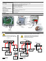
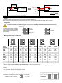
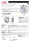
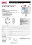
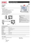
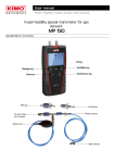
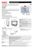
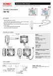
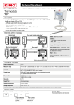
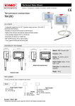
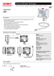
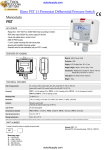
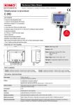
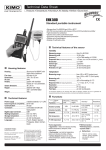
Differential pressure transmitter
CP 114 – CP 115
KEY POINTS
- Ranges from -500/+500 mbar to -2000/+2000 mbar (according to models)
- Configurable intermediary ranges
- 0-10 V or 4-20 mA output, active, power supply 24 Vac/Vdc (3-4 wires) or 4-20 mA
output, passive loop, power supply from 16 to 30 Vdc (2 wires)
- ABS V0 housing, IP65, with or without display
- “¼ turn” system mounting with wall-mount plate
- Housing with simplified mounting system
FEATURES OF THE HOUSING
90 mm
46 mm
Material : ABS V0 as per UL94
Protection : IP65
109 mm
Display : LCD 10 digits. Size : 50 x 17 mm
Height of digits : Value : 10 mm ; Unit : 5 mm
Connections : safety Ø 6.2 mm
Cable gland : for cables Ø 8 mm maximum
Weight : 143 g
TECHNICAL FEATURES
Measurement units
mbar, inWG, mmHG, PSI, mmH2O, daPa, hPa, kPa
Accuracy*
±1.5% of reading ±3 mbar
Response time
1/e (63%) 0.3 s
Resolution
1 mbar ; 0.1 inWG ; 1 mmHG ; 1 mmH2O ; 1 hPa ; 10 daPa ; 0.1 kPa ; 0.1 PSI
Autozero
Manual with push-button
Type of fluid
Air and neutral gases
Overpressure tolerated
CP114 : 1400 mbar ; CP115 : 4100 mbar
Operating temperature
From 0 to +50 °C
Storage temperature
From -10 to +70 °C
*All the accuracies indicated in this technical datasheet were stated in laboratory conditions, and can be guaranteed for measurements carried out in the same conditions, or carried out with calibration compensation.
PART NUMBER
To order, just add the codes to complete the part number :
Example : CP 114 – AO
Pressure transmitter measuring range -500/+500 mbar, 0-10 V
or 4-20 mA active, with display
CP 11
Display
Measuring range
4 : -500/+500 mabr
5 : -2000/+2000 mbar
O : with display
N : without display
Power supply / Output
A : Active – 24 Vac/Vdc – 0-10 V or 4-20 mA
P : Passive – 16/30 Vdc – 4-20 mA
TECHNICAL SPECIFICATIONS
Output / Supply
- active sensor 0-10 V or 4-20 mA (alim. 24 Vac/Vdc ± 10%), 3-4 wires
- passive loop 4-20 mA (power supply 16/30 Vdc), 2 wires
- maximum load : 500 Ohms (4-20 mA)
- minimum load : 1 K Ohms (0-10 V)
Consumption
2 VA (0-10 V) or max. 22 mA (4-20 mA)
Electromagnetical compatibility
EN61326
Electrical connection
Screw terminal block for cables Ø0.05 to 2.5 mm2
Communication to PC
Kimo USB-mini Din cable
Environment
Air and neutral gases
CONNECTIQUES
Inside the front housing
Fixed back housing
Removable front face
LCC-S
connection
DIP Switchs
Power supply terminal
block
Output terminal
block
Autozero
Cable gland
Pressure
connections
ELECTRICAL CONNECTIONS – as per NFC15-100 standard
This connection must be made by a qualified technician. To make the connection, the transmitter must not be energized.
To make a 3-wire connection, before powering up the
transmitter, please connect the output ground to the
input ground. See drawing below.
For CP114/115 – AO models and CP114/115 – AN
models with 0-10 V or 4-20 mA output – active, 4 wires :
VP GND IP
1
4
+
3
2
+
5
6
+
7
VP GND IP
1
2
6
- +
4 5
+
3
+
7
GND IP
4
wires
+
- +
4 5
3 wires
N
6
L
7
-
V
Regulator display or
PLC/BMS
passive type
+
Power supply
24 Vdc
4-20 mA output
or
-
+
A
4 wires
+
- Power supply
V
24 Vdc
Regulator display or
PLC/BMS passive type
or
N L
6 7
Sortie 4-20 mA
or
-
Regulator display or
PLC/BMS active type
0-10 V output
-
+
+
A
Regulator display or PLC/BMS
N
L
Power supply
24 Vac
class II
active type
0-10 V output
3 wires
or
L
N Power supply
24 Vac
class II
For CP114/115 – PO models and CP114/115 – PN models with 4-20 mA output – passive :
Power supply
16-30 Vdc
-
2 wires
6
IT -
Display/regulator/PLC
passive type
A
Vdc +
or
IT -
2 wires
A 16-30 Vdc
-
5
5
+
+
7
-
6
+
7
Vdc +
Display/regulator/PLC
active type
...
...
...
...
2 wires
SETTINGS AND USE OF THE TRANSMITTER
➢
Autozero
To perform an autozero, unplug the 2 pressure connections tubes and press the “Autozero” key.
When an autozero has been performed, “On” green light turns off then turns on, and on transmitters equipped with a display, “autoZ” is displayed.
➢
Configuration
To configure the transmitter, it must not be energized. Then, you can make the settings required, with the DIP switches (as shown on the
drawing below). When the transmitter is configured, you can power it up.
On-off switch
1
2
3
4
To configure the transmitter, unscrew the 4
screws from the housing then open it. DIP
switches allowing the different settings are
then accessible.
1
2
3
4
Measuring
ranges setting
Standard range or
central 0 setting
Left DIP switch
➢
Output setting
Units setting
Right DIP switch
Measuring range settings – left DIP switch
To set a measuring range, put the 1, 2 and 3 on-off switches as indicated in the table below.
Type of
transmitter
1
1
1
1
1
2
2
2
2
2
3
3
3
3
3
4
Combination 1
4
Combination 2
4
Combination 3
4
Combination 4
4
Combination 5
CP114
CP115
CP114
CP115
CP114
CP115
CP114
CP115
CP114
CP115
mbar
100
500
200
750
300
1000
400
1500
500
2000
inWG
40.0
200.0
80.0
300.0
120.0
400.0
160.0
600.0
200.00
800.0
kPa
10.0
50.0
20.0
75.0
30.0
100.0
40.0
150.0
50.0
200.0
PSI
2.0
10.0
4.0
15.0
6.0
20.0
8.0
30.0
10.0
40.0
mmHg
80
400
160
600
240
800
320
1200
400
1600
mmH2O
1000
5000
2000
7500
3000
10 000
4000
15 000
5000
20000
daPa
1.0
5.0
2.0
7.5
3.0
10.0
4.0
15.0
5.0
20.0
hPa
100
500
200
750
300
1000
400
1500
500
2000
●
●
Measuring ranges of the CP114 transmitter on the ±500 mbar range according to the measurement unit.
Measuring ranges of the CP115 transmitter on the ±2000 mbar range according to the measurement unit.
Example :
● From 0 to 750 mmH O, measuring range is 750 mmH O.
2
2
●
From -500 mbar to +500 mbar, measuring range is 1000 mbar.
➢
Standard range / central zero setting – left DIP switch
Configurations
To set the type of measuring range, put the on-off switch 4 as indicated beside :
Example 0-100 mbar : Full scale / 0
Central zero
(0 / 100 mbar)
(-50 mbar / 0 / +50 mbar)
Combinations
Full scale
Central zero
Please follow carefully the combinations beside with the DIP switch. If the combination is wrongly done, the following message will appear
on the display of the transmitter “CONF ERROR”. In that case, you will have to unplug the transmitter, place the DIP switches correctly, and
then power the transmitter up.
➢
Output setting – right DIP switch (CP114/115 – AO and CP114/115 – AN models)
To set the type of analogue output, please put the on-off switch of the output as shown
beside.
Configurations
4-20 mA
1
2
3
4
Combinations
➢
0-10 V
Units setting – right DIP switch
1
2
3
4
Configurations
Combinations
mbar
1
2
3
4
inWG
1
2
3
4
kPa
1
2
3
4
PSI
mmH2O
mmHG
1
2
3
4
daPa
1
2
3
4
1
2
3
4
hPa
1
2
3
4
1
2
3
4
CONFIGURATION VIA LCC-S SOFTWARE (option)
An easy and friendly configuration with the software !
You can configure your own intermediary ranges.
Caution : the minimum difference between the high range and the low range is 20.
1
2
3
4
1
2
3
4
For example, it is possible to set the instrument from -20 to 0 mbar, from 0 to +20 mbar, or from -10 to +10 mbar...
• To access the configuration via software :
- Set the DIP switches as shown beside. Nota : the on-off switch 1 of the right DIP switch can be in
Left DIP switch
any position (selection of the analogue output 0-10 V or 4-20 mA)
- Connect the cable of the LCC-S to the connection of the transmitter.
• Please refer to the user manual of the LCC 100 to make the configuration.
The configuration of the parameters can be done either with the DIP switch or via software (you can not combine both solutions).
Right DIP switch
75 mm
MOUNTING
37.5 mm
8 mm
4.5 mm
14 mm
A
7.5 mm
MAINTENANCE
Please avoid any aggressive solvent. Please protect the transmitter and its probes from any cleaning product containing formalin, that may be used for
cleaning rooms or ducts.
OPTIONS AND ACCESSORIES
●
●
KIAL-100A : Power supply class 2 , 230 Vac input, 24
Vac output
LCC-S : configuration software with USB cable
●
●
●
Connection tube
Connection fittings
Through-connections
●
●
Straight connections
Spherical coupling nut
50 mm
A
68 mm
Once the transmitter is installed and powered up, please make an autozero to
guarantee the correct working of the transmitter in any position.
40 mm
23.75 mm
To mount the transmitter, mount the ABS plate on the wall (drilling : Ø6 mm, screws and pins are
supplied).
Insert the transmitter on the fixing plate (see A on the drawing beside). Rotate the housing in
clockwise direction until you hear a “click” which confirms that the transmitter is correctly installed.
FTang – transmitter_CP114-115 – 08/03/13 – RCS (24) Périgueux 349 282 095 Non-contractual document – We reserve the right to modify the characteristics of our products without prior notice.
To set a measurement unit, put the on-off switches 2, 3 and 4 of the units as shown in the table below.