1
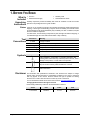
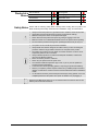
User Manual
TABLE OF CONTENTS
1. Before You Begin .......................................................................................................... 4
What Is Included ............................................................................................................................. 4
Unpacking Instructions .................................................................................................................... 4
Claims..................................................................................................................................................... 4
Text Conventions ............................................................................................................................ 4
Symbols .......................................................................................................................................... 4
Disclaimer ....................................................................................................................................... 4
Product at a Glance ........................................................................................................................ 5
Safety Notes .................................................................................................................................... 5
2. Introduction ................................................................................................................... 6
Features .......................................................................................................................................... 6
Product Description ......................................................................................................................... 6
Mounting ......................................................................................................................................... 6
Programming Concepts .................................................................................................................. 6
Front Panel Overview...................................................................................................................... 7
Front Panel View .................................................................................................................................... 7
Front Panel Controls ............................................................................................................................... 7
Control Descriptions ............................................................................................................................... 8
Back Panel View ..................................................................................................................................... 9
Back Panel Ports .................................................................................................................................... 9
DMX Polarity Switch Diagram ......................................................................................................... 9
Product Dimensions ...................................................................................................................... 10
3. Setup .............................................................................................................................11
AC Power ...................................................................................................................................... 11
Mounting ....................................................................................................................................... 11
Setting Up the Board ..................................................................................................................... 11
DMX Cabling ................................................................................................................................. 11
DMX Cabling Diagram .......................................................................................................................... 11
Fixture Addressing ........................................................................................................................ 11
4. Programming ................................................................................................................12
Program Mode .............................................................................................................................. 12
Entering Program Mode........................................................................................................................ 12
Exiting Program Mode .......................................................................................................................... 12
Programming a Scene or Scenes ................................................................................................. 13
Editing a Scene or Scenes ................................................................................................................... 13
Deleting a Scene or Scenes ................................................................................................................. 13
Programming a Chase .................................................................................................................. 14
Add Mode ............................................................................................................................................. 14
Deleting a Step or Steps in a Chase ..................................................................................................... 15
Edit Mode ............................................................................................................................................. 15
Page 2 of 21
Foot-C™ User Manual Rev. 1
5. Playback .......................................................................................................................16
Playback Mode .............................................................................................................................. 16
Scene Playback ............................................................................................................................ 16
Chase Playback ............................................................................................................................ 16
Speed ............................................................................................................................................ 16
Fade .............................................................................................................................................. 16
Auto Mode ..................................................................................................................................... 17
Audio Triggering ............................................................................................................................ 17
Blackout ........................................................................................................................................ 17
Tap Sync ....................................................................................................................................... 17
Manual Override ............................................................................................................................ 17
MIDI Operation .............................................................................................................................. 18
MIDI Map .............................................................................................................................................. 18
6. Maintenance .................................................................................................................19
Product Maintenance .................................................................................................................... 19
7. Technical Specifications..............................................................................................19
Returns .............................................................................................................................20
Contact Us ........................................................................................................................21
Foot-C™ User Manual Rev. 1
Page 3 of 21
1. BEFORE YOU BEGIN
What Is
Included
Unpacking
Instructions
Claims
Text
Conventions
Symbols
·
·
·
·
Foot-C™
External Power Supply
Warranty Card
Quick Reference Guide
Carefully unpack the product immediately and check the container to make sure all the
parts are in the package and are in good condition.
If the box or the contents (the product and included accessories) appear damaged from
shipping, or show signs of mishandling, notify the carrier immediately, not Chauvet. Failure
to report damage to the carrier immediately may invalidate your claim. In addition, keep the
box and contents for inspection.
For other issues, such as missing components or parts, damage not related to shipping, or
concealed damage, file a claim with Chauvet within 7 days of delivery.
Convention
1—512
50/60
Settings
Menu > Settings
<ENTER>
ON
Symbol
Meaning
A range of values
A set of values of which only one can be chosen
A menu option not to be modified
A sequence of menu options to be followed
A key to be pressed on the product’s control panel
A value to be entered or selected
Meaning
Critical installation, configuration, or operation information. Not
following these instructions may make the product not work, cause
damage to the product, or cause harm to the operator.
Important installation or configuration information. The product
may not function correctly if this information is not used.
Useful information.
Disclaimer
The information and specifications contained in this document are subject to change
without notice. Chauvet assumes no responsibility or liability for any errors or omissions
that may appear in this manual. Chauvet reserves the right to update the existing
document or to create a new document to correct any errors or omissions.
You can download the latest version of this document from www.chauvetlighting.com.
© Copyright 2015 Chauvet. All rights reserved.
Electronically published by Chauvet in the United States of America.
Page 4 of 21
Author
Date
Editor
Date
R. Isenstadt
04/28/15
A. Leon
05/01/15
Foot-C™ User Manual Rev. 1
Product at a
Glance
Use on Dimmer
Outdoor Use
Sound-Active
DMX
Master/Slave
Safety Notes
x
x
P
P
x
Auto Programs
Auto-ranging Power Supply
Replaceable Fuse
User-Serviceable
x
P
x
x
Please read the following Safety Notes carefully before working with the product. The
Notes include important safety information about installation, usage, and maintenance.
·
·
·
·
·
·
Always connect the product to a grounded circuit to avoid the risk of electrocution.
Always disconnect the product from the power source before cleaning.
Make sure the power cord is not crimped or damaged.
Never disconnect the product from power by pulling or tugging on the cord.
Make sure there are no flammable materials close to the product when operating.
Do not touch the product’s housing when operating because it may be very hot.
·
·
The product is not intended for permanent installation.
Always make sure that the voltage of the outlet to which you are connecting the
product is within the range stated on the decal or rear panel of the product.
The product is for indoor use only! (IP20) To prevent risk of fire or shock, do not
expose the product to rain or moisture.
Always install the product in a location with adequate ventilation, at least 20 in
(50 cm) from adjacent surfaces.
Never connect the product to a dimmer.
Never carry the product from the power cord.
The maximum ambient temperature (Ta) is 104 °F (40 °C). Do not operate the
product at higher temperatures.
In the event of a serious operating problem, stop using the product immediately.
Never try to repair the product. Repairs carried out by unskilled people can lead to
damage or malfunction. Please contact the nearest authorized technical assistance
center.
To eliminate unnecessary wear and improve its lifespan, during periods of non-use
completely disconnect the product from power via breaker or by unplugging it.
·
·
·
·
·
·
·
·
Keep this User Manual for future use. If you sell the product to someone else, be sure
that they also receive this document.
Foot-C™ User Manual Rev. 1
Page 5 of 21
2. INTRODUCTION
Features
Product
Description
Mounting
Programming
Concepts
·
·
·
·
·
·
·
Controls up to 6 fixtures, up to 36 channels total
Designed to work with fixtures that have up to 6 channels
Guitar pedal-style buttons
Create and control a full light show of chases, scenes, fades, and more
Built-in Tap Sync, Auto, and Sound modes
MIDI input
Direct audio line input for triggering scenes
· Fits in the CHS-25 VIP Gear Bag
Foot-C™ is a compact 36-channel DMX foot controller that can control up to 6
six-channel fixtures and store 12 sets of chases with up to 24 steps each. Ideal for
6-channel fixtures, it has rugged guitar pedal-style buttons that can trigger Automated
and Sound-Active modes, as well as control chases and scenes. LED displays make it
easy to navigate the controller in any environment.
The Foot-C™ is designed with 4 rubber feet so it can be placed on a table top for
programming, and then floor-mounted for playback. The product is not rack-mountable.
The Foot-C™ uses DMX addressing and values to control products. See Fixture
Addressing for more information.
Looks are created by using the faders to send DMX values to the products. The looks
are saved into scenes or as steps in chases. The scenes and chases are played back
at different speeds and with different types of triggers.
· Looks are created in Program mode. The products are selected with the fixture buttons.
The knobs are moved to control the products and create looks. Then the looks are
saved to scenes or chases with the program button.
See Programming for more information.
· Scenes and chases are played back in Playback mode. Timing of playback is set with
the speed and time functions, audio triggers, the Tap Sync function, or MIDI input. See
Playback for more information.
Looks can be created in playback mode, but they cannot be saved.
Page 6 of 21
Foot-C™ User Manual Rev. 1
The Foot-C™ is laid out with the Fixture buttons (<1>–<6>) on the top left, the color
and sensitivity knobs on the top right, the LED displays along the middle, and the guitar
pedal-style buttons along the bottom. The rear panel of the product has the ports and
power connection. See Back Panel View for information about the back panel and its
ports.
Front Panel
Overview
Front Panel
View
1
2
3
4
5
6
7
8
Front Panel
Controls
9
Item
1
2
3
4
5
6
7
8
9
10
11
12
Foot-C™ User Manual Rev. 1
10
11
12
Button or Knob
Fixture selection buttons 1–6 with indicator LEDs
Program button
Blackout button
Delete button/MIDI channel select. LED indicator will light orange when
in MIDI selection mode.
Color/control knobs: red, green, blue, amber, white, and UV
Sound sensitivity knob
Displays
Mode pedal-style button - switches between chases and scenes
Up pedal-style button - navigates upward through a list or increases
numerical value when in a function
Down pedal-style button - navigates downward through a list or
decreases numerical value when in a function
Function (Enter) pedal-style button - enables the currently displayed
menu or sets the currently selected value
Music/Auto/Blackout pedal-style button. Also toggles program modes.
Page 7 of 21
Control
Descriptions
Button or Fader
Description
FIXTURE
<1>–<6>
Buttons that select lights to control and set the default DMX addresses
of the channel faders. The corresponding LEDs indicate when a light
is selected.
Note: These buttons are inclusive. Pressing one, then another,
selects both lights. To deselect a light, press it again and make
sure the LED indicator is off.
BLACKOUT
The <BLACKOUT> button will darken all fixtures. To turn blackout off,
press the <BLACKOUT> button again. The
<MUSIC/AUTO/BLACKOUT> pedal will also activate and deactivate
the blackout feature.
PROGRAM
Button used to enter the programming mode. Allows you to program a
scene, chase, or sequence thereof.
DELETE
Button used to delete scenes individually. Delete a scene by pressing
and holding the <DELETE> button until the LED display flashes.
<DELETE> button also controls the MIDI channel select.
Color/Control
Knobs
Audio
Sensitivity
Knob
LED Displays
<MODE>
Pedal Button
<UP>
Pedal Button
<DOWN>
Pedal Button
<FUNCTION
(ENTER)>
Pedal Button
Knobs to control the manual adjustment of red, green, blue, amber,
white and UV (000–255); or the DMX channel of the Fixtures 1–6.
Knob that adjusts the board’s sensitivity to sound and music.
Display that shows various types of information about current
selections and whether it is in Program or Playback mode:
· Blackout - indicates that blackout is active and the board is not
sending DMX signals.
· Program - indicates that the board is in Program mode.
· Music - indicates that the board is in Music Trigger mode.
· Auto - indicates that the board is in Auto Trigger mode.
· Chase - shows the current chase in Playback or Program mode.
· Scene - shows the current scene in Playback or Program mode.
Button that switches between Chase mode and Scenes mode. Hold to
activate the Tap Sync feature.
Button that moves up through banks of scenes, or up through the
steps in a chase.
Button that moves down through banks of scenes, or down through
the steps in a chase.
Button used while programming to switch between the Speed and
Fade functions, or to confirm a selection.
Button used in playback to quickly switch between Music mode, Auto
mode, or to blackout all fixtures.
·
<MUSIC/AUTO/
BLACKOUT>
Pedal Button
Page 8 of 21
To turn the blackout off, you must press and hold the
<MUSIC/AUTO/BLACKOUT> pedal button again.
·
While in Tap Sync mode, press the
<MUSIC/AUTO/BLACKOUT> pedal button to the beat to set your
chase timing.
Also used for toggling program modes. With program activated, press
to switch between Add and EdIT.
Foot-C™ User Manual Rev. 1
Back Panel View
MIDI In
DMX Out
Audio Line
Input
Back Panel
Ports
Port
MIDI In
DMX Out
DC Power In
Power On/Off Switch
Audio Line Input
DMX Polarity Switch
Power On/Off
Switch
DC Power In
DMX Polarity
Switch
Function
5-pin MIDI port for connecting a MIDI signal.
3-pin DMX port for connecting to other products.
Connects to the external power supply.
Toggle switch that turns the Foot-C™ on and off.
RCA Input for external audio triggering.
Toggle switch for changing DMX polarity.
DMX Polarity
Switch
Diagram
All Chauvet lights use a negative pin 2 and positive pin 3, so the polarity switch should
be set as shown above—towards the DMX Control Out port. Other manufacture’s lights
might be different.
For more information about
www.chauvetlighting.com.
Foot-C™ User Manual Rev. 1
DMX,
download
the
DMX
Primer
from
Page 9 of 21
Product Dimensions
14.2 in
360 mm
7.2 in
183 mm
2.6 in
66 mm
Page 10 of 21
Foot-C™ User Manual Rev. 1
3. SETUP
AC Power
The Foot-C™ has an external auto-ranging power supply and it can work with an input
voltage range of 100 to 240 VAC, 50/60 Hz. To determine the product’s power requirements
(circuit breaker, power outlet, and wiring), use the current value listed on the label affixed to
the power supply’s back panel, or refer to the product’s specifications chart. The listed
current rating indicates the product’s average current draw under normal conditions.
·
Always connect the product to a protected circuit (circuit breaker or fuse). Make
sure the product has an appropriate electrical ground to avoid the risk of
electrocution or fire.
·
To eliminate unnecessary wear and improve its lifespan, during periods of nonuse completely disconnect the product from power via breaker or by
unplugging it.
Never connect the product to a rheostat (variable resistor) or dimmer circuit, even if
the rheostat or dimmer channel serves only as a 0 to 100% switch.
Mounting
The Foot-C™ is designed only for floor or table mounting. Make sure adequate ventilation
is provided around the product.
Setting Up the
Board
DMX Cabling
In order to use the controller it must be connected to the products with DMX cables and
the products must be addressed correctly. The sections below described DMX cabling and
DMX addressing.
DMX cabling is required to get DMX values from the board to the products. Connect the DMX cable
from the DMX Out of the board to the DMX In of the first product in the rig.
Then connect another DMX cable from the DMX Out of the first product in the rig to the DMX In of
the next product. Continue connecting until all the products are connected.
DMX Cabling
Diagram
DMX
In
DMX
In
DMX
Out
1st Product
Fixture
Addressing
DMX
Out
DMX
In
DMX
Out
Additional
Products
3rd Product
2nd Product
The Foot-C™ uses DMX addressing. The Foot-C™ controls lights with specific DMX
addresses and the lights must be addressed correctly for the Foot-C™ to control them.
More than one light can have the same DMX address, but lights with the same DMX
address should be the same type of light.
Below is a chart showing the Foot-C™ DMX addresses and the corresponding fixture
buttons.
FIXTURE Button
Starting Address
Range
<1>
1
1–6
<2>
7
7–12
<3>
13
13–18
<4>
19
19–24
<5>
25
25–30
<6>
31
31–36
This product has program memory. All looks exist not only during the current
session, but can also be saved or recalled after switching the power OFF.
Foot-C™ User Manual Rev. 1
Page 11 of 21
4. PROGRAMMING
Program
Mode
Program mode is used to program for playback. In Program mode, lighting looks are
created and saved for playback. There are three parts to programming for playback.
·
Programming lights: selecting and controlling them to create looks.
·
Programming scenes: saving the looks into scenes.
or
·
Programming chases: saving the looks into steps in a chase.
The next section describes how to program lights, scenes, and chases, and how to
modify and delete scenes and chases.
Output can be adjusted in Playback mode, but the looks created in Playback mode
cannot be saved to memory.
Entering
Program Mode
To enter program mode do the following:
1. Turn the board on.
2. Press and hold <PROGRAM> for three seconds.
3. The program indicator light, next to the <PROGRAM> button, will light up.
4. Release <PROGRAM>.
Exiting Program
Mode
To exit program mode do the following:
1. Press and hold <PROGRAM> for three seconds.
2. The program indicator light, next to the <PROGRAM> button, will turn off.
3. Release <PROGRAM>.
Page 12 of 21
Foot-C™ User Manual Rev. 1
Programming
a Scene or
Scenes
The Foot-C™ has one bank of scenes, separate from the chase banks, for saving and
playing back recorded scenes. To record a scene, follow the instructions below:
1. Enter program mode.
2. Press <MODE> until the left display reads SCENE.
3. Use <UP> and <DOWN> to select the desired scene.
4. Use buttons <1>–<6> to select the fixture(s) to be programmed.
5. Use the Color/Number knobs to set the desired output.
6.
7.
Repeat steps 4 and 5 until all fixtures output as desired.
Press <PROGRAM>. The displays will flash, showing the scene was saved.
8.
9.
Repeat steps 3–7 for up to 24 scenes.
Exit program mode.
Scenes are intended to be used for static looks, as opposed to chases which are
intended for changing looks.
Editing a Scene
or Scenes
After being recorded, any scene can be re-programmed. To edit a scene, do the following:
1. Enter program mode.
2. Press <MODE> until the left display reads SCENE.
3. Use <UP> and <DOWN> to select the scene to be edited.
4. Use buttons <1>–<6> to select the fixture(s) to be programmed.
5. Use the Color/Number knobs to set the desired output.
6.
7.
Repeat steps 4 and 5 until all fixtures output as desired.
Press <PROGRAM>. The displays will flash, showing the scene was saved.
8.
9.
Repeat steps 3–7 for all scenes that require editing.
Exit program mode.
Looks created or edited in program mode will not be stored in the system memory
until <PROGRAM> has been pressed.
Deleting a Scene
or Scenes
To delete a scene, do the following:
1. Enter program mode.
2. Press <MODE> until the left display reads SCENE.
3. Use <UP> and <DOWN> to select the scene to be deleted.
4. Press and hold <DELETE> for three seconds. The displays will flash, indicating the
scene was deleted.
5. Release <DELETE>.
6.
7.
Repeat steps 3–5 until all desired scenes have been deleted.
Exit program mode.
Deleted scenes can not be restored without redesigning the look.
Foot-C™ User Manual Rev. 1
Page 13 of 21
Programming
a Chase
Chase mode gives the user access to a bank of 12 chases, each with up to 24 steps. The
distinction between chases and scenes allows the user to switch between moving chases
and static scenes at will.
Add Mode
Add mode allows the user to record new steps in a chase, either to a previously unrecorded
chase. Or to an already established chase. To program a chase:
1.
2.
3.
4.
Enter program mode.
Press <MODE> until the left display reads CHASE.
Press <MUSIC AUTO BLACKOUT> until the display on the right reads Add.
Use <FUNCTION (ENTER)> to scroll through the chase bank until the desired chase is
selected.
A chase with no recorded steps will show xx 00/00 (chase 1–12 step 0 out of 0) on the
middle display.
5. Use buttons <1>–<6> to select the fixture(s) to be programmed.
6. Use the Color/Number knobs to set the desired output.
7. Repeat steps 5 and 6 until all fixtures output as desired.
8. Press <PROGRAM>. The displays will flash, showing the step was saved. The product
will automatically move on to the next step.
The last step that was saved to memory will show on the middle display. For example:
03 03/03 (chase 3, step 3 of 3) will change to 03 04/04 (chase 3, step 4 of 4) after
pressing <PROGRAM>, indicating the next step to be programmed will be 03 05/05
(chase 3, step 5 of 5).
9. Repeat steps 5–8 for up to 24 steps.
10. Exit program mode.
To add a step in the middle of a chase:
1.
2.
3.
4.
5.
6.
7.
8.
9.
Enter program mode.
Press <MODE> until the left display reads CHASE.
Press <MUSIC AUTO BLACKOUT> until the display on the right reads Add.
Use <FUNCTION (ENTER)> to scroll through the chase bank until the desired chase is
selected.
Use <UP> and <DOWN> to select the step before the step to be inserted.
Use buttons <1>–<6> to select the fixture(s) to be programmed.
Use the Color/Number knobs to set the desired output.
Repeat steps 6 and 7 until all fixtures output as desired.
Press <PROGRAM>. The displays will flash, showing the inserted step was saved. The
middle display will indicate the inserted step. For example, if the display read 01 07/13
before pressing <PROGRAM>, it will read 01 08/14 after saving the new step.
Chases are intended to be used for changing looks, as opposed to scenes which are
intended for static looks
Page 14 of 21
Foot-C™ User Manual Rev. 1
Deleting a Step
or Steps in a
Chase
To delete a step or steps in a chase, do the following:
1. Enter program mode.
2. Press <MODE> until the left display reads CHASE.
3. Use <FUNCTION (ENTER)> to select the chase to be shortened.
4. Use <UP> and <DOWN> to select the step to be deleted.
5. Press and hold <DELETE> for three seconds. The displays will flash, indicating the
step was deleted. All steps after the deleted step will move down the queue to replace
it.
For example: If step 3 is deleted, step 4 will become step 3, step 5 will become step 4,
etc.
6. Release <DELETE>.
7. Repeat steps 4–6 until all desired steps have been deleted.
8. Exit program mode or continue programming chases/scenes.
Deleted steps can not be restored without redesigning the look.
Edit Mode
Foot-C™ User Manual Rev. 1
To edit a step or steps in a chase, follow the instructions below:
1. Enter program mode.
2. Press <MODE> until the left display reads CHASE.
3. Press <MUSIC AUTO BLACKOUT> until the display on the right reads EdIT.
4. Use <FUNCTION (ENTER)> to select the chase to be edited.
5. Use <UP> and <DOWN> to select the step to be edited.
6. Use buttons <1>–<6> to select the fixture(s) to be programmed.
7. Use the Color/Number knobs to set the desired output.
8. Repeat steps 6 and 7 until all fixtures output as desired.
9. Press <PROGRAM> to record the changes. The displays will flash, indicating the
changes were saved.
10. Repeat steps 5–9 until all desired changes to this chase are completed.
11. Edit another chase or exit program mode.
Page 15 of 21
5. PLAYBACK
Playback
Mode
Playback is used to play back saved scenes and chases. It is the mode to use when the
show is happening. In playback mode, the saved scenes and chases are triggered to play
back. There are four playback types:
·
Scene Playback - Playing back saved scenes.
·
Chase Playback - Playing back saved chases.
·
MIDI Playback - Using a MIDI input signal to play back scenes and chases.
·
Live Playback - Controlling the outputs without the use of scenes or chases. Not
recommended.
To operate any of the modes that offer amber, white, or UV color options, the
selected fixture must be capable of outputting that corresponding color light.
Scene
Playback
Chase
Playback
Scene playback triggers the looks saved into the scene bank in order from 1 up to 24 for
playback with auto, audio, MIDI, or Tap Sync triggering. The middle display shows the
current scene.
To enter Scene Playback mode from Chase Playback mode, press <MODE>. Scene 1 will
automatically be selected. If there is no look saved to Scene 1, it will skip to the first saved
scene.
·
For manual triggering of scenes, run the Foot-C™ in Auto mode and set the
speed to 0. Use <UP> and <DOWN> to select the desired scene.
·
Scenes with nothing programmed will be skipped in playback.
Chase playback triggers a specific chase (1–12) for playback with auto, audio, MIDI, or Tap
Sync triggering. The middle display shows the selected chase, the current step, and the
total number of steps in that chase.
To enter Chase Playback mode from Scene Playback mode, press <MODE>. Chase 1 will
automatically be selected. Use <UP> and <DOWN> to select a chase.
There is no way to manually trigger the steps in a chase in playback mode.
Page 16 of 21
Speed
The speed setting determines how long each scene or step will be active in Auto mode,
before the next scene or step is triggered.
To set speed, do the following:
1. Play back a scene or chase.
2. Press <FUNCTION (ENTER)> until SPEEd 0–16 shows on the middle display.
3. Use <UP> and <DOWN> to select the desired speed. 0 will halt auto triggering. 1–16
is in order from slowest to fastest speeds.
4. Press <FUNCTION (ENTER)> until the display shows the current scene or chase to
exit speed setting.
Fade
The fade setting determines how long it takes one scene or step to change, or fade, to the
next scene or step.
To set fade, follow the instructions below:
1. Play back a scene or chase.
2. Press <FUNCTION (ENTER)> until FAdE 0–16 shows on the middle display.
3. Use <UP> and <DOWN> to select the desired fade. 0 will set the scenes or steps to
snap immediately to the next when triggered. 1–16 is in order from fastest to slowest
fade curves.
4. Press <FUNCTION (ENTER)> until the display shows the current scene or chase to
exit fade setting.
Foot-C™ User Manual Rev. 1
Auto Mode
Auto mode sets the scenes or the steps in chases to trigger automatically, based on the set
speed and fade times.
To enable Auto mode, do the following:
1. Play back a scene or chase.
2. Press <MUSIC AUTO BLACKOUT> until the display on the right shows AUTO.
Audio
Triggering
Audio mode sets the scenes or steps in chases to respond to audio triggers, from either the
internal microphone, or an external audio source through the Audio Line Input jack on the
rear panel.
To enable Audio Triggering, follow the instructions below:
1. Play back a scene or chase.
2. Press <MUSIC AUTO BLACKOUT> until the display on the right shows MUSIC.
3. Turn the AUDIO SENS knob up until the scenes or steps are triggered by sound as
desired.
Blackout
Blackout mode sets all DMX outputs to zero while active. There are two ways to activate or
deactivate Blackout mode:
·
Press <BLACKOUT>
or
·
Press and hold <MUSIC AUTO BLACKOUT> for three seconds.
Either method can deactivate Blackout, regardless of how it was activated.
While Blackout mode is active, the indicator LED next to <BLACKOUT> will light up.
Tap Sync
The Tap Sync feature allows the user to set the auto speed with their foot. To activate Tap
Sync:
1. Play back a scene or chase in Auto mode.
2. Press and hold <MODE> for three seconds. The display on the right will show TAPSY.
3. Release <MODE>.
4. Press <MUSIC AUTO BLACKOUT> at the desired tempo. Do this several times to
ensure the tempo is set.
To deactivate Tap Sync, press <MODE>.
When Tap Sync is activated, the fixture automatically adds a fade time of ‘1’. This
can be removed by pressing the <DOWN> pedal button in the Fade menu.
Manual
Override
Foot-C™ User Manual Rev. 1
During playback, the Color knobs can take priority over the scene or chase playing back.
To manually override a recorded program, do the following:
1. Play back a scene or chase in any mode.
2. Use buttons <1>–<6> to select the fixture(s) to be overridden.
3. Use the Color/Number knobs to alter the output of the selected fixture(s).
Once a Color knob has been moved, the knob will completely supersede the program for
the selected fixture(s). For example: If all fixtures are set to output blue for a scene, fixture 1
is selected, and the BLUE knob is turned all the way down, then fixture 1 will not output
blue.
To turn off Manual Override, use buttons <1>–<6> to deselect any selected fixtures.
Page 17 of 21
MIDI
Operation
MIDI Map
The Foot-C™ can be externally controlled by a MIDI signal through the MIDI in port on the
rear panel. This will work at any time, as long as there is a MIDI input.
To select the MIDI receiving channel:
1. Press and hold <DELETE> for three seconds. The indicator next to <DELETE> will
light up.
2. Release <DELETE>. The display will have changed to show the MIDI receiving
channel.
3. Use <UP> and <DOWN> to select a MIDI receiving channel 1–16.
4. Press and hold <DELETE> for three seconds. The indicator next to <DELETE> will
turn off.
5. Release <DELETE>. The display will have returned to normal.
·
The controller will only respond to MIDI commands on the selected MIDI
channel when SPEEd is set to 0.
Perform all MIDI control using NOTE_ON or PROGRAM CHANGE commands.
·
All other MIDI instructions are ignored.
To stop a chase, send the BLACKOUT ON note.
·
NOTE_ON
MIDI Note
Function (Turns On/Off)
00–23
SCENE 1-24 ON
24–35
CHASE 1-12 ON
36
TAPSYNC
127
Blackout
PROGRAM CHANGE
MIDI Note
Function (Turns On/Off)
10–21
CHASE 1-12 ON
30–53
SCENE 1-24 ON
60–76
Set Speed 1-16
80–95
Set Fade 1-16
100
Blackout On
101
Blackout Off
MIDI operation always runs in the background during use.
Page 18 of 21
Foot-C™ User Manual Rev. 1
6. MAINTENANCE
Product
Maintenance
Dust build-up reduces performance and can cause overheating. This can lead to reduction
of the product’s life and/or mechanical wear. To maintain optimum performance and
minimize wear, clean your lighting products at least twice a month. However, be aware that
usage and environmental conditions could be contributing factors to increase the cleaning
frequency.
To clean the product, follow the instructions below:
1. Unplug the product from power.
2. Wait until the product is at room temperature.
3. Use a vacuum (or dry compressed air) and a soft brush to remove dust collected on
the external surface.
4. Clean all transparent surfaces (display lenses) with a mild soap solution, ammoniafree glass cleaner, or isopropyl alcohol.
5. Apply the solution directly to a soft, lint free cotton cloth or a lens cleaning tissue.
6. Softly drag any dirt or grime to the outside of the transparent surface.
7. Gently polish the transparent surfaces until they are free of haze and lint.
Always dry the transparent surfaces carefully after cleaning them.
7. TECHNICAL SPECIFICATIONS
Dimensions and
Weight
Length
Width
Height
Weight
7.2 in (183 mm)
14.2 in (360 mm)
2.6 in (66 mm)
4 lb (1.9 kg)
Note: Dimensions in inches rounded to the nearest decimal digit.
Power
Thermal
DMX
Ordering
Foot-C™ User Manual Rev. 1
Value
Foot-C™
Input Voltage
Fixed
External Power Supply
Switching
Range
12 VDC, 1 A
100 to 240 VAC, 50/60 Hz
Voltage Selection
Fixed
Auto-ranging
Maximum External Temp.
Cooling System
104 °F (40 °C)
Convection
Output Connector
Channel Range
3-pin XLR
36
Product Name
Item Code
UPC Number
Foot-C™
09081024
781462213725
Page 19 of 21
RETURNS
In case you need to get support or return a product:
· If you are located in the U.S., contact Chauvet World Headquarters.
· If you are located in the UK or Ireland, contact Chauvet Europe Ltd.
· If you are located in Mexico, contact Chauvet Mexico.
· If you are located in Benelux, contact Chauvet Europe BVBA.
· If you are located in any other country, DO NOT contact Chauvet. Instead, contact your
local distributor. See www.chauvetlighting.com for distributors outside the U.S., UK,
Ireland, Mexico, or Benelux.
If you are located outside the U.S., UK, Ireland, Mexico, or Benelux, contact your
distributor of record and follow their instructions on how to return Chauvet
products to them. Visit our website www.chauvetlighting.com for contact details.
Call the corresponding Chauvet Technical Support office and request a Return
Merchandise Authorization (RMA) number before shipping the product. Be prepared to
provide the model number, serial number, and a brief description of the cause for the
return.
Send the merchandise prepaid, in its original box, and with its original packing and
accessories. Chauvet will not issue call tags.
Clearly label the package with the RMA number. Chauvet will refuse any product
returned without an RMA number.
Write the RMA number on a properly affixed label. DO NOT write the RMA number
directly on the box.
Before sending the product, clearly write the following information on a piece of paper
and place it inside the box:
· Your name
· Your address
· Your phone number
· RMA number
· A brief description of the problem
Be sure to pack the product properly. Any shipping damage resulting from inadequate
packaging will be your responsibility. FedEx packing or double-boxing are
recommended.
Chauvet reserves the right to use its own discretion to repair or replace returned
product(s).
Page 20 of 21
Foot-C™ User Manual Rev. 1
CONTACT US
WORLD HEADQUARTERS - Chauvet
General Information
Address: 5200 NW 108th Avenue
Sunrise, FL 33351
Voice:
(954) 577-4455
Fax:
(954) 929-5560
Toll free: (800) 762-1084
Technical Support
Voice:
(954) 577-4455 (Press 4)
Fax:
(954) 756-8015
Email:
[email protected]
World Wide Web www.chauvetlighting.com
UNITED KINGDOM AND IRELAND - Chauvet Europe Ltd.
General Information
Address: Unit 1C
Brookhill Road Industrial Estate
Pinxton, Nottingham, UK
NG16 6NT
Voice:
+44 (0)1773 511115
Fax:
+44 (0)1773 511110
Technical Support
Email:
[email protected]
World Wide Web
www.chauvetlighting.co.uk
MEXICO - Chauvet Mexico
General Information
Address: Av. Santa Ana 30
Parque Industrial Lerma
Lerma, Mexico C.P. 52000
Voice:
+52 (728) 285-5000
Technical Support
Email:
[email protected]
World Wide Web www.chauvet.com.mx
CHAUVET EUROPE - Chauvet Europe BVBA
General Information
Address:Stokstraat 18
9770 Kruishoutem
Belgium
Voice: +32 9 388 93 97
Technical Support
Email:
[email protected]
World Wide Web www.chauvetlighting.eu
Outside the U.S., United Kingdom, Ireland, Mexico, or Benelux contact your dealer. Follow their
instructions to request support or to return a product. Visit our website for contact details.
Foot-C™ User Manual Rev. 1
Page 21 of 21