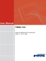
1
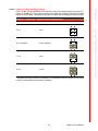
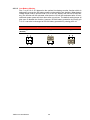
User Manual
TREK-743
Vehicle Mounted Computer
with 7" TFT LCD
Copyright
The documentation and the software included with this product are copyrighted 2008
by Advantech Co., Ltd. All rights are reserved. Advantech Co., Ltd. reserves the right
to make improvements in the products described in this manual at any time without
notice. No part of this manual may be reproduced, copied, translated or transmitted
in any form or by any means without the prior written permission of Advantech Co.,
Ltd. Information provided in this manual is intended to be accurate and reliable. However, Advantech Co., Ltd. assumes no responsibility for its use, nor for any infringements of the rights of third parties, which may result from its use.
Acknowledgements
AMD and Geode are trademarks of Advanced Micro Devices Corporation.
Microsoft Windows and MS-DOS are registered trademarks of Microsoft Corp.
All other product names or trademarks are properties of their respective owners.
Product Warranty (2 years)
Advantech warrants to you, the original purchaser, that each of its products will be
free from defects in materials and workmanship for two years from the date of purchase.
This warranty does not apply to any products which have been repaired or altered by
persons other than repair personnel authorized by Advantech, or which have been
subject to misuse, abuse, accident or improper installation. Advantech assumes no
liability under the terms of this warranty as a consequence of such events.
Because of Advantech’s high quality-control standards and rigorous testing, most of
our customers never need to use our repair service. If an Advantech product is defective, it will be repaired or replaced at no charge during the warranty period. For outof-warranty repairs, you will be billed according to the cost of replacement materials,
service time and freight. Please consult your dealer for more details.
If you think you have a defective product, follow these steps:
1. Collect all the information about the problem encountered. (For example, CPU
speed, Advantech products used, other hardware and software used, etc.) Note
anything abnormal and list any onscreen messages you get when the problem
occurs.
2. Call your dealer and describe the problem. Please have your manual, product,
and any helpful information readily available.
3. If your product is diagnosed as defective, obtain an RMA (return merchandise
authorization) number from your dealer. This allows us to process your return
more quickly.
4. Carefully pack the defective product, a fully-completed Repair and Replacement
Order Card and a photocopy proof of purchase date (such as your sales receipt)
in a shippable container. A product returned without proof of the purchase date
is not eligible for warranty service.
5. Write the RMA number visibly on the outside of the package and ship it prepaid
to your dealer.
TREK-743 User Manual
Part No. 2006074303
Edition 4
Printed in Taiwan
January 2009
ii
Declaration of Conformity
This product has passed the CE test for environmental specifications. Test conditions
for passing included the equipment being operated within an industrial enclosure. In
order to protect the product from being damaged by ESD (Electrostatic Discharge)
and EMI leakage, we strongly recommend the use of CE-compliant industrial enclosure products.
FCC Class B
Note: This equipment has been tested and found to comply with the limits for a Class
B digital device, pursuant to part 15 of the FCC Rules. These limits are designed to
provide reasonable protection against harmful interference in a residential installation. This equipment generates, uses and can radiate radio frequency energy and, if
not installed and used in accordance with the instructions, may cause harmful interference to radio communications. However, there is no guarantee that interference
will not occur in a particular installation. If this equipment does cause harmful interference to radio or television reception, which can be determined by turning the equipment off and on, the user is encouraged to try to correct the interference by one or
more of the following measures:
! Reorient or relocate the receiving antenna.
! Increase the separation between the equipment and receiver.
! Connect the equipment into an outlet on a circuit different from that to which the
receiver is connected.
! Consult the dealer or an experienced radio/TV technician for help.
FM
This equipment has passed the FM certification. According to the National Fire Protection Association, work sites are classified into different classes, divisions and
groups, based on hazard considerations. This equipment is compliant with the specifications of Class I, Division 2, Groups A, B, C and D indoor hazards.
Technical Support and Assistance
1.
2.
Visit the Advantech web site at www.advantech.com/support for the latest
information about the product.
Contact the distributor, sales representative, or Advantech's customer service
center for technical support if you need additional assistance. Please have the
following information ready before you call:
– Product name and serial number
– Description of your peripheral attachments
– Description of your software (operating system, version, application software,
etc.)
– A complete description of the problem
– The exact wording of any error messages
iii
TREK-743 User Manual
Warnings, Cautions and Notes
Warning! Warnings indicate conditions, which if not observed, can cause personal
injury!
Caution! Cautions are included to help you avoid damaging hardware or losing
data. e.g.
There is a danger of a new battery exploding if it is incorrectly installed.
Do not attempt to recharge, force open, or heat the battery. Replace the
battery only with the same or equivalent type recommended by the manufacturer. Discard used batteries according to the manufacturer's
instructions.
Note!
Notes provide optional additional information.
Document Feedback
To assist us in making improvements to this manual, we would welcome comments
and constructive criticism. Send all such in writing to: [email protected]
Packing List
Before setting up, check that the items listed below are included, in good condition. If
any item does not accord with the table, please contact your dealer immediately.
! TREK-743 series Vehicle Mounted Computer
! Accessories for TREK-743
! Warranty card
! Power cord: DC power inlet cable (180 cm - for TREK-743 only)
! "Drivers, Utilities and User Manual" CD-ROM
! End User License Agreement (XPE and WinCE model)
TREK-743 User Manual
iv
Safety Instructions
1.
2.
3.
Read these safety instructions carefully.
Keep this User Manual for later reference.
Disconnect this equipment from any AC outlet before cleaning. Use a damp
cloth. Do not use liquid or spray detergents for cleaning.
4. For plug-in equipment, the power outlet socket must be located near the equipment and must be easily accessible.
5. Keep this equipment away from humidity.
6. Put this equipment on a reliable surface during installation. Dropping it or letting
it fall may cause damage.
7. The openings on the enclosure are for air convection. Protect the equipment
from overheating. DO NOT COVER THE OPENINGS.
8. Make sure the voltage of the power source is correct before connecting the
equipment to the power outlet.
9. Position the power cord so that people cannot step on it. Do not place anything
over the power cord.
10. All cautions and warnings on the equipment should be noted.
11. If the equipment is not used for a long time, disconnect it from the power source
to avoid damage by transient overvoltage.
12. Never pour any liquid into an opening. This may cause fire or electrical shock.
13. Never open the equipment. For safety reasons, the equipment should be
opened only by qualified service personnel.
14. If one of the following situations arises, get the equipment checked by service
personnel:
15. The power cord or plug is damaged.
16. Liquid has penetrated into the equipment.
17. The equipment has been exposed to moisture.
18. The equipment does not work well, or you cannot get it to work according to the
user's manual.
19. The equipment has been dropped and damaged.
20. The equipment has obvious signs of breakage.
21. DO NOT LEAVE THIS EQUIPMENT IN AN ENVIRONMENT WHERE THE
STORAGE TEMPERATURE MAY GO BELOW -40° C OR ABOVE 60° C (140°
F). THIS COULD DAMAGE THE EQUIPMENT. THE EQUIPMENT SHOULD BE
IN A CONTROLLED ENVIRONMENT.
22. CAUTION: DANGER OF EXPLOSION IF BATTERY IS INCORRECTLY
REPLACED. REPLACE ONLY WITH THE SAME OR EQUIVALENT TYPE
RECOMMENDED BY THE MANUFACTURER, DISCARD USED BATTERIES
ACCORDING TO THE MANUFACTURER'S INSTRUCTIONS.
23. The sound pressure level at the operator's position according to IEC 704-1:1982
is no more than 70 dB (A).
DISCLAIMER: This set of instructions is given according to IEC 704-1. Advantech
disclaims all responsibility for the accuracy of any statements contained herein.
v
TREK-743 User Manual
Wichtige Sicherheishinweise
1.
2.
3.
Bitte lesen sie Sich diese Hinweise sorgfältig durch.
Heben Sie diese Anleitung für den späteren Gebrauch auf.
Vor jedem Reinigen ist das Gerät vom Stromnetz zu trennen. Verwenden Sie
Keine Flüssig-oder Aerosolreiniger. Am besten dient ein angefeuchtetes Tuch
zur Reinigung.
4. Die NetzanschluBsteckdose soll nahe dem Gerät angebracht und leicht
zugänglich sein.
5. Das Gerät ist vor Feuchtigkeit zu schützen.
6. Bei der Aufstellung des Gerätes ist auf sicheren Stand zu achten. Ein Kippen
oder Fallen könnte Verletzungen hervorrufen.
7. Die Belüftungsöffnungen dienen zur Luftzirkulation die das Gerät vor überhitzung schützt. Sorgen Sie dafür, daB diese Öffnungen nicht abgedeckt werden.
8. Beachten Sie beim. AnschluB an das Stromnetz die AnschluBwerte.
9. Verlegen Sie die NetzanschluBleitung so, daB niemand darüber fallen kann. Es
sollte auch nichts auf der Leitung abgestellt werden.
10. Alle Hinweise und Warnungen die sich am Geräten befinden sind zu beachten.
11. Wird das Gerät über einen längeren Zeitraum nicht benutzt, sollten Sie es vom
Stromnetz trennen. Somit wird im Falle einer Überspannung eine Beschädigung
vermieden.
12. Durch die Lüftungsöffnungen dürfen niemals Gegenstände oder Flüssigkeiten in
das Gerät gelangen. Dies könnte einen Brand bzw. elektrischen Schlag auslösen.
13. Öffnen Sie niemals das Gerät. Das Gerät darf aus Gründen der elektrischen
Sicherheit nur von authorisiertem Servicepersonal geöffnet werden.
14. Wenn folgende Situationen auftreten ist das Gerät vom Stromnetz zu trennen
und von einer qualifizierten Servicestelle zu überprüfen:
15. Netzkabel oder Netzstecker sind beschädigt.
16. Flüssigkeit ist in das Gerät eingedrungen.
17. Das Gerät war Feuchtigkeit ausgesetzt.
18. Wenn das Gerät nicht der Bedienungsanleitung entsprechend funktioniert oder
Sie mit Hilfe dieser Anleitung keine Verbesserung erzielen.
19. Das Gerät ist gefallen und/oder das Gehäuse ist beschädigt.
20. Wenn das Gerät deutliche Anzeichen eines Defektes aufweist.
21. VOSICHT: Explisionsgefahr bei unsachgemaben Austausch der Batterie.Ersatz
nur durch densellben order einem vom Hersteller empfohlene-mahnlichen Typ.
Entsorgung gebrauchter Batterien navh Angaben des Herstellers.
22. ACHTUNG: Es besteht die Explosionsgefahr, falls die Batterie auf nicht fachmännische Weise gewechselt wird. Verfangen Sie die Batterie nur gleicher oder
entsprechender Type, wie vom Hersteller empfohlen. Entsorgen Sie Batterien
nach Anweisung des Herstellers.
23. Der arbeitsplatzbezogene Schalldruckpegel nach DIN 45 635 Teil 1000 beträgt
70dB(A) oder weiger.
Haftungsausschluss: Die Bedienungsanleitungen wurden entsprechend der IEC704-1 erstellt. Advantech lehnt jegliche Verantwortung für die Richtigkeit der in
diesem Zusammenhang getätigten Aussagen ab.
TREK-743 User Manual
vi
Safety Precaution - Static Electricity
Follow these simple precautions to protect yourself from harm and the products from
damage.
! To avoid electrical shock, always disconnect the power from your PC chassis
before you work on it. Don't touch any components on the CPU card or other
cards while the PC is on.
! Disconnect power before making any configuration changes. The sudden rush
of power as you connect a jumper or install a card may damage sensitive electronic components.
Warning! 1.
2.
3.
4.
Input voltage rated: 9-36 Vdc.
Transport: carry the unit with both hands and handle with care.
Maintenance: to properly maintain and clean the surfaces, use only
approved products or clean with a dry applicator.
CompactFlash: Turn off the power before inserting or removing
CompactFlash storage cards.
European Contact information:
Advantech Europe GmbH
Kolberger Straße 7
D-40599 Düsseldorf, Germany
Tel: 49-211-97477350
Fax: 49-211-97477300
TREK-743 User Manual
vii
Contents
Chapter
1
General Information ............................1
1.1
1.2
Introduction ............................................................................................... 2
General Specifications .............................................................................. 2
1.2.1 General ......................................................................................... 2
1.2.2 Standard PC Functions................................................................. 3
1.2.3 PCI Bus Ethernet Interface ........................................................... 3
1.2.4 Touchscreen ................................................................................. 3
1.2.5 Environment.................................................................................. 4
LCD Specifications.................................................................................... 4
Table 1.1: LCD Specifications ..................................................... 4
Dimensions ............................................................................................... 4
Figure 1.1 TREK-743 dimensions................................................ 4
1.3
1.4
Chapter
2
System Setup .......................................5
2.1
2.3
2.4
2.5
2.6
A Quick Tour of the Vehicle Mounted ....................................................... 6
Figure 2.1 Front view of the TREK-743 ....................................... 6
Figure 2.2 Left side of the TREK-743 .......................................... 6
Figure 2.3 Rear view of the TREK-743........................................ 7
Figure 2.4 Vehicle mounted computer I/O ................................... 7
Installation Procedures.............................................................................. 8
2.2.1 Connecting the Power Cord.......................................................... 8
Table 2.1: Pin Definition of Power Cord ...................................... 8
2.2.2 Connecting the Keyboard or Mouse ............................................. 8
2.2.3 Switching on the Power ................................................................ 8
Running the BIOS Setup Program ............................................................ 9
Installing System Software........................................................................ 9
Installing the Drivers................................................................................ 10
Programming Function Keys and GPIO/CAN BUS................................. 10
3
Hardware & Peripheral Installation ..11
3.1
3.2
3.3
Overview of Hardware Installation & Upgrading ..................................... 12
Installing the Storage Device and Memory ............................................. 12
Installing Optional Accessories ............................................................... 12
3.3.1 Installing Ram-mount Kits ........................................................... 12
Figure 3.1 RAM mount kits ........................................................ 12
3.3.2 Installing the MiniPCI Wireless LAN Module............................... 13
Figure 3.2 MiniPCI Wireless LAN module ................................. 13
3.3.3 Installing the GPS and GSM / GPRS Modules ........................... 14
Figure 3.3 GPS module ............................................................. 14
Figure 3.4 GSM / GPRS module ............................................... 15
Figure 3.5 Installing the SIM card. ............................................. 15
3.3.4 Installing the Blue Tooth Module................................................. 16
Figure 3.6 Blue Tooth module ................................................... 16
Fuse ........................................................................................................ 17
3.4.1 Fuse Specifications..................................................................... 17
3.4.2 Fuse Installation and Replacement............................................. 17
Figure 3.7 Installing the fuse...................................................... 17
2.2
Chapter
3.4
Chapter
4
Jumper Settings and Connectors ....19
ix
TREK-743 User Manual
4.1
4.2
4.3
4.4
Chapter
Chapter
Chapter
Chapter
Chapter
Setting Jumpers and Switches................................................................ 20
4.1.1 Locating Jumpers and Switches ................................................. 20
Table 4.1: Jumpers & LEDS on the Motherboard ..................... 20
4.1.2 Locating Jumpers and LEDs on the Motherboard ...................... 21
Figure 4.1 Locating Jumpers / LEDs ......................................... 21
4.1.3 Connectors on the Motherboard ................................................. 22
Table 4.2: Connectors on the Motherboard............................... 22
4.1.4 Locating Connectors on the Motherboard .................................. 23
Figure 4.2 Locating Connectors on the front side...................... 23
Figure 4.3 Locating Connectors on the back side ..................... 23
CPU Installation ...................................................................................... 24
Jumper Settings ...................................................................................... 24
4.3.1 CMOS Clear for External RTC (JP1) .......................................... 24
Table 4.3: Clear CMOS / External RTC (JP1)........................... 24
4.3.2 Power Feature Setting (JP3) ...................................................... 24
Table 4.4: Ignition Input Switch Setting (JP3) ........................... 24
Table 4.5: Power off / Hard off Delay Setting (JP3) .................. 25
Table 4.6: Low Battery Monitor (JP3)........................................ 26
COM Port Interface ................................................................................. 27
Table 4.7: Serial Port Default Settings ...................................... 27
4.4.1 COM Port Pin 9 Power Output Setting (CN27)........................... 28
Table 4.8: COM Port Pin 9 Power Output Setting (CN27) ........ 28
4.4.2 COM Port Pin 9 Power Output Value Setting (JP2).................... 28
Table 4.9: COM Port Pin 9 Power Output Value Setting (JP2) . 28
5
AMD Chipset...................................... 29
5.1
5.2
Introduction ............................................................................................. 30
Further Information ................................................................................. 30
6
Graphic Chipset ................................ 31
6.1
6.2
Introduction ............................................................................................. 32
Figure 6.1 Display properties..................................................... 32
Figure 6.2 Adapter menu........................................................... 33
Figure 6.3 LCD resolution selection .......................................... 33
Further Information ................................................................................. 33
7
Audio.................................................. 35
7.1
Introduction ............................................................................................. 36
7.1.1 Installation of Audio Driver.......................................................... 36
8
LAN..................................................... 37
8.1
8.2
Introduction ............................................................................................. 38
Installation of LAN Driver ........................................................................ 38
9
Touchscreen...................................... 39
9.1
Introduction ............................................................................................. 40
9.1.1 General Information .................................................................... 40
9.1.2 General Specifications................................................................ 40
Installation of Touchscreen Driver .......................................................... 40
Further Information ................................................................................. 40
9.2
9.3
TREK-743 User Manual
x
Chapter 10
Bluetooth ............................................41
10.1
10.2
Introduction ............................................................................................. 42
Installation of Blue Tooth Driver .............................................................. 42
Appendix A
Pin Assignments ...............................43
A.1
Internal Speaker Connector (CN2 on PCM-028) .................................... 44
Table A.1: Internal Speaker Connector (CN2 on PCM-028)...... 44
COM1, 2 (CN17,19) ................................................................................ 44
Table A.2: COM1, 2 (CN17,19).................................................. 44
GPIO / CAN BUS Connector (CN31) ...................................................... 45
Table A.3: GPIO / CAN BUS Connector (CN31) ....................... 45
Inverter / Touch / USB Connector (CN18) .............................................. 46
Table A.4: Inverter / Touch / USB Connector (CN18)................ 46
Power Inlet .............................................................................................. 47
Table A.5: Power inlet................................................................ 47
A.2
A.3
A.4
A.5
Appendix B
GPRS Setting .....................................49
B.1
B.2
GPRS Settings in the OS ........................................................................ 50
B.1.1 Setting up the Modem................................................................. 50
B.1.2 Setting up an Internet Connection .............................................. 58
Other Information .................................................................................... 65
Appendix C
Software API ......................................67
C.1
Software API ........................................................................................... 68
Appendix D
BIOS Settings.....................................69
D.1
Power Fail Function Setting in BIOS....................................................... 70
Figure D.1 Main Menu: Power Management Setup ................... 70
Figure D.2 Power Fail Function................................................. 70
Feature of PC Health Status .................................................................. 71
D.2
xi
TREK-743 User Manual
TREK-743 User Manual
xii
Chapter
1
1
General Information
This chapter gives background
information on the TREK-743
Vehicle Mounted Computer.
Sections include:
! Introduction
! General Specifications
! LCD Specifications
! Dimensions
1.1 Introduction
TREK-743 is a fanless and compact vehicle mounted computer designed for a wide
range of commercial vehicle applications: delivery, fleet management and warehousing/logistics.
The ruggedized aluminum enclosure without ventilation holes makes the TREK-743
waterproof and dust proof. The wide range power input suits vehicles such as forklifts
and trucks, which typically operate with 12 V, 24 VDC power. TREK-743 provides
options for real-time communication and data capture in vehicle to improve overall
productivity.
1.2 General Specifications
1.2.1 General
!
!
!
Dimensions: (W x H x D): 255 x 160 x 50 mm.
Weight: 1.7 kg.
Power supply:
– Input voltage: 9 ~ 36Vdc, support ignition cold crank (min 6Vdc).
– Ignition on/off
– Low battery shut-down protection threshold (optional): When the vehicle
battery voltage level drops below 11V for more than 30 seconds, TREK-743
will automatically shut down in order to prevent “deep discharge” situations
and TREK-743 can be re-activated only when the voltage is > 11V.
– Power on delay: Default 2 seconds. When the TREK-743 is powered on via
ignition key, the system will delay 2 seconds to power on.
– Power off delay: Default 5 seconds. When TREK-743 power is controlled by
ignition key and turns off by the key (ignition=off), the TREK-743 will start the
shut procedure after 5 seconds.
– Hard off delay: Default 30 seconds. When TREK-743 power is controlled by
ignition key and turns off by the key (ignition=off), the TREK-743 will cut off
the 5VSB power after 30 seconds. In this event when the shutdown process
is longer then 30 seconds, the power will be shut down hard, turning off the
TREK-743's power and 5VSB.
Note!
!
!
!
For more detail of function please refer to Chapter 4, Section 4.3.2 of
this manual.
Power consumption: The maximum current consumption is about 32.4 watts.
The power consumption is 12 watts in normal mode (with only XPE running; no
I/O device and modules connected to the TREK-743).
Front panel and back cover: IP65 Sealed; NEMA4 compliant
(Not including the I/O ports).
Enclosure: Ruggedized aluminum without ventilation holes.
TREK-743 User Manual
2
!
!
!
!
!
!
!
!
!
!
!
!
!
!
!
!
!
!
1.2.3 PCI Bus Ethernet Interface
!
!
!
Chipset: Realtek RTL8100CL PCI local bus Ethernet controller.
Ethernet interface: Full compliance with IEEE 802.3u 100Base-T and 10 BaseT specifications. Includes software drivers and boot ROM that supports both
RPL and PXE.
100/10Base-T auto-sensing capability.
1.2.4 Touchscreen
!
!
!
!
!
!
Type: Analog Resistive
Light transmission: 80%
Controller: RS-232 interface
Power consumption: <5.5 V@ 20 mA
Durability: > 10 million depressions
Software driver: Supports Windows XP/XP Embedded, WinCE
3
TREK-743 User Manual
General Information
!
CPU: AMD LX800 500MHz.
Chipset: Integrated in AMD CS5536AD South Bridge.
BIOS: Award 256 KB Flash BIOS, ACPI 2.0 Compliant.
System chipset: AMD CS5536AD.
System memory: One 200-pin SODIMM sockets, accepts up to 1 GB DDR266/
333 SDRAM. (Win CE image supports up to 512 MB SDRAM)
Solid state disk: Supports one 50-pin socket for Compact-Flash type I/II (True
IDE mode).
Serial ports: Two RS-232/422/485 serial ports. All ports are compatible with
16C550. UARTs, +5V power supply selectable.
Universal serial bus (USB) port: Supports up to three EHCI USB2.0.
Mini PCI bus expansion slot: Accepts one type III A/B mini PCI bus card.
Bluetooth: One Class2 Bluetooth V2.0 + EDR module.
Watchdog timer: 63-level timer intervals automatically generate system reset
when the system stops due to a program error or EMI. Jumperless selection and
software enabled/disabled.
RTC Battery: 3.0 V @ 195 mA lithium battery.
Power management: Supports power saving modes including Normal/
Standby/Suspend modes. APM 1.2 compliant.
Digital I/O: Optically isolated 4 digital input and 4 digital output
CAN bus:
• Built in CAN/RS-232 converter
• Max transmission speed up to 1 Mbps for CAN and 57600 bps for RS-232
interface
• Supports both CAN 2.0A and CAN 2.0B
• Provides a group of RS-232 devices a method to be the network system (Fullduplex communication mode of RS-232 devices is not supported)
Audio controller: ACL650 AC97 Ver. 2.0 compliant interface, Multi stream
Direct sound and Direct Sound 3D acceleration.
Stereo sound: 18-bit full-duplex codec.
Audio interface: One 1.5W speaker, one microphone.
Optional modules: 12 channels GPS, quad-band GSM/GPRS, MiniPCI WLAN
card.
Chapter 1
1.2.2 Standard PC Functions
1.2.5 Environment
!
!
!
!
!
Operating temperature: -20 ~ 60° C (-4 ~ 140° F)
Relative humidity: 10 ~ 95% @ 40° C (non-condensing)
Shock: 30 G peak acceleration (11 msec duration)
Certifications: EMC: CE, FCC, CCC Safety: UL, CUL, CE; CCC, CB.
Vibration: 5 ~ 500 Hz 4.5G RMS random vibration
1.3 LCD Specifications
Table 1.1: LCD Specifications
Definition
Detail
Display type:
7” TFT LCD
Max. resolution:
800 x 480
Colors:
262K
Dot size (mm)
0.0635 x 0.1905
Luminance:
400 cd/m2
Viewing Angle (Horizon/Vertical):
100° / 120°
.
Note!
1.
2.
The Brightness control is defined by Function key on the front
panel.
The color LCD display installed in the Vehicle Mounted Computer
is high-quality and reliable. However, it may contain a few defective
pixels which do not always illuminate. With current technology, it is
impossible to completely eliminate defective pixels. Advantech is
actively working to improve this technology.
1.4 Dimensions
All dimensions are in millimeters.
50.00
160.00
254.70
Figure 1.1 TREK-743 dimensions
TREK-743 User Manual
4
Chapter
2
2
System Setup
This chapter details system setup
on TREK-743.
Sections include:
! A Quick Tour of the Vehicle
Mounted Computer
! Installation Procedures
! Running the BIOS Setup Program
2.1 A Quick Tour of the Vehicle Mounted
Before starting to set up the Vehicle Mounted Computer, take a moment to become
familiar with the locations and purposes of the controls, drives, connectors and ports,
which are illustrated in the figures below. When the Vehicle Mounted Computer is
placed upright on the desktop, its front panel appears as shown in Figure 2.1. Look
for the brightness control key, microphone and power LED indicator on the right, five
illuminated programmable function keys on the bottom, and one USB connector with
water/dust-proof cover and a speaker on the left.
Figure 2.1 Front view of the TREK-743
Facing the left side of the Vehicle Mounted Computer, the power button is visible on
the lower side, as shown in Figure 2.2.
Figure 2.2 Left side of the TREK-743
TREK-743 User Manual
6
Chapter 2
The Vehicle Mounted Computer rear cover is fitted with several standard VESA
mounting holes, (75 x 75mm) and other extra holes for mounting. The unit is completely sealed, and there are no ventilation holes on the back cover, as shown in Figure 2.3.
System Setup
Figure 2.3 Rear view of the TREK-743
The I/O section is located on the bottom of the Vehicle Mounted Computer, as shown
in Figure 2.4
B
F
D
A
E
C
A: 2 x USB 2.0
B: 2 x COM (RS232/422/485)
C: One 10/100 Base-T ethernet
D: CAN BUS & 4 DI/DO
E: GPS antenna connector (reserved)
F: DC power inlet
Figure 2.4 Vehicle mounted computer I/O
7
TREK-743 User Manual
2.2 Installation Procedures
2.2.1 Connecting the Power Cord
Connect the three pin waterproof power cord to the DC inlet of the Vehicle Mounted
Computer. On the open-wire end, one pin is reserved for positive voltage and is
marked, "+"; one pin is reserved for ground and is marked, "-"; and, one pin is
reserved for the ignition signal with an “ignition” mark.
Note!
Power on/off the TREK-743 via the TREK-743's power switch. Please
connect its "+ " and " ignition" pins together with the power source's "+".
Or change the JP3 jumper setting. (For JP3 jumper setting please see
section 4.3.2.1)
Note!
Ignition on/off setting : The TREK-743 supports an ignition on/off function so that you can power on/off the TREK-743 via the ignition signal/
voltage. Either connect the TREK-743's "ignition" pin to vehicle ignition
and the TREK-743 "+-" to "+-" ; or connect the TREK-743's "ignition &
+" pins together with power source's "+" , and "-" to "-". Please also set
the "power on after power failure” function to "always on" in BIOS.(for
BIOS settings, please see Appendix D). The delay on/off will be active
once the ignition on/off is selected.
Table 2.1: Pin Definition of Power Cord
Pin
Definition
Color
1
+
yellow
3
-
black
4
Ignition
white
2.2.2 Connecting the Keyboard or Mouse
Before starting the computer, it is required to connect the mouse or keyboard to the
USB ports.
2.2.3 Switching on the Power
The power switch is located on the bottom of the computer.
TREK-743 User Manual
8
2.4 Installing System Software
Recent releases of operating systems from major vendors include setup programs
which load automatically and guide users through the entire process of operating
system installation. The guidelines below help to determine the steps necessary to
install your operating system on the computer hard drive.
Note!
Some distributors and system integrators may have already preinstalled system software prior to shipment of your Vehicle Mounted
Computer.
The BIOS of the computer supports system boots-up directly from the CD-ROM drive
whenever it is connected using a USB interface. Insert the system installation CDROM into the CD-ROM drive.
Power on the computer, or reset the system by pressing the “Ctrl” + “Alt” + “Del” keys
simultaneously. The computer will automatically load the operating system from the
diskette or CD-ROM.
When presented with the opening screen of a setup / installation program, simply follow the onscreen instructions. The setup program guides users through preparations
of the hard drive, and installation of the operating system.
When presented with an operating system command prompt, like, A:\>, then it is necessary to partition and format the hard drive, and manually copy the operating system files to it. Refer to the operating system user instructions about partitioning and
formatting the hard drive.
9
TREK-743 User Manual
System Setup
In most cases, the computer will have been properly set up and configured by the
dealer or SI prior to delivery. However, it may still be necessary to adjust some of the
computer's BIOS (Basic Input-Output System) setup programs to change the system
configuration data, like the current date and time, or the specific type of hard drive
currently installed.
The setup program is stored in read-only memory (ROM). It can be accessed either
when turning on or resetting the computer, by pressing the “Del” key on the keyboard
immediately after powering up the computer.
The settings that are specified with the setup program are recorded in a special area
of the memory called CMOS RAM. This memory is backed up by a battery so that it
will not be erased when turning off or resetting the system. Whenever the power is
turned on, the system reads the settings stored in CMOS RAM and compares them
to the equipment check conducted during the “power on self-test” (POST). If an error
occurs, an error message is displayed on screen, and the user is prompted to run the
setup program.
Chapter 2
2.3 Running the BIOS Setup Program
2.5 Installing the Drivers
After installing system software, the computer is ready to set up the AMD chipset,
VGA, audio, LAN, and touch screen functions. All the pre-requisite drivers are stored
on a CD-ROM disc entitled “Drivers and Utilities” (Check the correct wording on the
CD, which can be found in the accessory box.)
The utility directory includes multimedia programs. Some drivers and utilities in the
CD-ROM disc have their own text files which help users install the drivers and understand their functions.
These files are a very useful supplement to the information in this manual. For more
details of driver installation please refers to Chapter 5 to 10 of this manual.
Note!
The drivers and utilities used for the TREK-743 are subject to change
without notice. If in doubt, check Advantech's website or contact our
application engineers for the latest information regarding drivers and
utilities.
2.6 Programming Function Keys and GPIO/CAN
BUS
The Vehicle Mount Computer provides five function keys, GPIO and CAN bus as
shown in section 2.1. These functions must be activated with the correct software,
that’s why we provide an AP library for customers to design their own software. Refer
to Appendix C for more detail.
Chapter
3
3
Hardware & Peripheral
Installation
This chapter details the installation of hardware for TREK-743.
Sections include:
! Overview of Hardware Installation and Upgrading
! Installing the Storage Device
and Memory
! Installing Optional Accessories
! Fuse
3.1 Overview of Hardware Installation & Upgrading
The Vehicle Mounted Computer consists of a PC-based computer that is housed in a
ruggedized aluminum enclosure. Any maintenance or hardware upgrades can be
completed after removing both cover panels.
Warning!
Warning! Do not remove the ruggedized aluminum covers until verifying that no
power is flowing within the computer. Power must be switched off and
the power cord must be unplugged. Take care in order to avoid injury or
damage to the equipment.
3.2 Installing the Storage Device and Memory
The Vehicle Mounted Computer can only use a CompactFlash Card (CFC) as a storage device. Put the CFC into the CF slot and insert the RAM into the 200-pin
SODIMM socket on the main board.
3.3 Installing Optional Accessories
Optional accessories, like mounting kits or other functional modules are available for
purchase to complement TREK-743. The following are instructions for accessory
installation.
3.3.1 Installing Ram-mount Kits
Three different types of RAM-MOUNT kits are available to fit various applications;
RAM-MOUNT-01 and RAM-MOUNT-02 support units weighing up to 4.5 kg (approximate 10 lbs); RAM-MOUNT-03 and RAM-MOUNT-05E mount supports units weighing up
to 6.75 kg (approximate 15 lbs).
Figure 3.1 RAM mount kits
TREK-743 User Manual
12
1.
2.
3.
Insert the WLAN module into the MiniPCI slot on Motherboard.
Fasten the cable between the connector #2, on the WLAN module and the
screw-in antenna hole on the rear cover.
Screw the antenna into the antenna hole on the rear cover shown as pictured
below.
WLAN
Module
2
Figure 3.2 MiniPCI Wireless LAN module
13
TREK-743 User Manual
Hardware & Peripheral Installation
1
Chapter 3
3.3.2 Installing the MiniPCI Wireless LAN Module
3.3.3 Installing the GPS and GSM / GPRS Modules
Follow the instructions to install these modules.
3.3.3.1 Install the GPS Module
1. Insert the GPS module #1, into the 4-pin hole on the motherboard. Solder the
GPS module carefully to fix it in place.
2. Fasten the cable between the connector on the GPS module and the screw the
antenna cable #2, into the antenna hole #3, on the rear cover.
3. Screw the external antenna onto the antenna hole on the rear cover.
GPS Module
2
1
Antenna
3
Figure 3.3 GPS module
TREK-743 User Manual
14
Hardware & Peripheral Installation
Antenna
GSM/GPRS
Module
1
3
2
4.
Figure 3.4 GSM / GPRS module
Install the SIM card from rear cover.
SIMCard
Figure 3.5 Installing the SIM card.
Note!
For more details, refer to Appendix B.
15
Chapter 3
3.3.3.2 Install the GSM / GPRS Module
1. Insert the GSM / GPRS module #1, onto the connector (CN16) on the back side
of motherboard. Solder the GPS module carefully to attach it to the motherboard.
2. Fasten the cable #2, between the connector on the GPRS module through the
hole in the middle of the motherboard, #3, and the screw the antenna into the
hole on rear cover.
3. Screw the antenna on the antenna hole on rear cover shown as below picture.
TREK-743 User Manual
3.3.4 Installing the Blue Tooth Module
1.
2.
Attach the bluetooth module onto the chassis. Align it with the groove pictured
below.
Fasten the cable between the connector on the blue tooth module and the connector (CN14) on the motherboard.
1
Blue tooth module
2
CN14
Figure 3.6 Blue Tooth module
TREK-743 User Manual
16
Chapter 3
3.4 Fuse
3.4.1 Fuse Specifications
!
!
Rating: 125 V AC, 5 A
Size: 5 x 9.7 mm
3.4.2 Fuse Installation and Replacement
Remove the fuse cover.
Install the new fuse or replace the damaged fuse with a new one.
Replace the fuse cover.
FUSE
Figure 3.7 Installing the fuse
17
TREK-743 User Manual
Hardware & Peripheral Installation
1.
2.
3.
Chapter
4
4
Jumper Settings and
Connectors
This chapter explains how to set
up the Vehicle Mounted Computer
hardware, including instructions
on setting jumpers and connecting peripherals, and how to set
switches and read indicators.
Be sure to read all the safety precautions before beginning the
installation procedure.
Sections include:
! Setting Jumpers
! CPU Installation
! Jumper Setting on MotherBoard
! COM-port Interface
4.1 Setting Jumpers and Switches
It is possible to configure the Vehicle Mounted Computer to match the needs of the
application by resetting the jumpers. A jumper is the simplest kind of electrical switch.
It consists of two metal pins and a small metal clip, often protected by a plastic cover
that slides over the pins to connect them. To “close” a jumper, connect the pins with
the clip. To “open” a jumper, remove the clip. Sometimes a jumper has three pins,
labeled 1, 2, and 3. In this case, connect either pins 1 and 2, or pins 2 and 3.
open
closed
closed 2-3
open
closed
closed 2-3
A pair of needle-nose pliers may be helpful when working with jumpers. If there are
any doubts about the best hardware configuration for the application, contact the
local distributor or sales representative before making any changes.
An arrow is used on the motherboard to indicate the first pin of each jumper.
4.1.1 Locating Jumpers and Switches
The motherboard of the Vehicle Mounted Computer has a number of jumpers that
are used to set various configuration options best suited to the function of applications installed on the computer. LEDs that indicate the system operation status are
also located on the motherboard. The table below lists the function of each jumper
and LED.
Table 4.1: Jumpers & LEDS on the Motherboard
Label
Function
JP1
CMOS clear for external RTC
JP2
COM1/COM2 Pin 9 power output value setting
CN27
COM1/COM2 Pin 9 Ring & power output type setting
JP3
Power feature setting
LED1
Wireless Radio operation indicator
LED2
CAN BUS operation indicator (Tx signal)
LED3
CAN BUS operation indicator (Rx signal)
LED5
GPRS operation indicator
LED6
Power indicator
LED7
CF operation indicator
TREK-743 User Manual
20
LED6
LED7
JP1
Chapter 4
4.1.2 Locating Jumpers and LEDs on the Motherboard
LED1
LED5
CN27
LED3
JP2
Figure 4.1 Locating Jumpers / LEDs
21
TREK-743 User Manual
Jumper Settings and Connectors
LED2
JP3
4.1.3 Connectors on the Motherboard
On-board connectors link the Vehicle Mounted Computer to external devices such as
hard disk drives. The table below lists the function of each connector.
Table 4.2: Connectors on the Motherboard
Label
Function
BH1
RTC battery
DIMM1
Dual In-line Memory Module Socket for SDRAM
CN2
RESET
FS3
Fuse
CN4
Power input connector
CN5
SIM holder
CN8
LAN
CN9
Mini PCI socket
CN10
Line in connector (Reserved)
CN11
Line out connector (Reserved)
CN13
USB1+USB2
CN14
USB3 (Blue Tooth)
CN16
Internal COM4 connector for GPRS
CN17
COM1
CN18
Internal COM3 for touchscreen / Inverter power connector / USB4
CN19
COM2
CN20
Internal COM5 connector for GPS
CN25
CF connector
CN26
BIOS
CN31
GPIO/CAN Connector
CN33
Connector for Function Board
CN35
Connector for LCD timing control Board
TREK-743 User Manual
22
Chapter 4
4.1.4 Locating Connectors on the Motherboard
BH1
CN2
CN25
DIMM1
CN9
CN20
CN11
CN26
CN14
CN33
CN35
CN4
CN18
CN13
CN8
CN19
CN31
CN17
Figure 4.2 Locating Connectors on the front side
CN16
FS3
CN5
Figure 4.3 Locating Connectors on the back side
23
TREK-743 User Manual
Jumper Settings and Connectors
CN10
4.2 CPU Installation
The CPU is embedded on the motherboard, therefore no settings for frequency ratio
or voltage are configured.
4.3 Jumper Settings
4.3.1 CMOS Clear for External RTC (JP1)
Warning! 1.
2.
To avoid damaging the computer, always turn off the power supply
before setting “Clear CMOS.”
Set the jumper back to “Normal Operation” before turning on the
power supply!
Table 4.3: Clear CMOS / External RTC (JP1)
Normal Operation (Default)
1
2
Clear CMOS
1
3
2
3
4.3.2 Power Feature Setting (JP3)
Three power feature settings are provided for in the Vehicle Mounted Computer: ignition input switch; power off / hard off delay; and low battery monitor. The functions
are controlled by adjusting the jumpers on the 10-pin connector, (JP3), as described
below.
4.3.2.1 Ignition Input Switch Setting
JP3 and BIOS settings determine whether the Vehicle Mounted Computer can be
activated by an ignition switch or not. By default JP3 is enabled. If you also change
the "Power on after power failure" to "always on" in BIOS (Appendix D), and connect
the ignition pin ( see section 2.2.1), this will enable automatic computer on/off with a
vehicle ignition/key. Ignition on/off is disabled by default or by disabling JP3.
Table 4.4: Ignition Input Switch Setting (JP3)
Ignition turn-on enable (Default)
1
TREK-743 User Manual
Ignition turn-on disable
1
2
24
2
Table 4.5: Power off / Hard off Delay Setting (JP3)
Hard off
0 sec
5 sec
5 sec (Default)
30 sec (Default)
1 min
5 min
5 min
15 min
Jumper setting
The power-off delay function is available in coordination with the ignition input power
control, as described in the previous section.
25
TREK-743 User Manual
Jumper Settings and Connectors
Off delay
Chapter 4
4.3.2.2 Power off / Hard off Delay Setting
Pins 3 to pin 6 of JP3 determine the duration of the time delay before powering off /
hard off (5VSB off). The jumper provides four different settings. Refer to the chart
below for more detail. The delay time may be custom set by making an OEM request.
4.3.2.3 Low Battery Monitor
Pins 7 to pin 10 of JP3 determine the optional low battery monitor function which is
designed to prevent the DC battery power on the vehicle from draining. When battery
voltage drops under a specific level (11V for DC12V battery and 22V for DC24V battery) the function will be activated, and then the OS will be terminated after 30 seconds and system power will shut down after one minute. The default setting keeps all
pins open to disable the function; however, DC24V battery protection by closing pin
7-8, or, it can also be changed to DC12V battery protection by closing pin 9-10.
Table 4.6: Low Battery Monitor (JP3)
No battery protection
(Default)
TREK-743 User Manual
DC24V battery protection
26
DC12V battery protection
Table 4.7: Serial Port Default Settings
Port
Address Range
Interrupt
COM1
3F8 ~ 3FF
4
COM2
2F8 ~ 2FF
3
COM3
3E8 ~ 3EF
7
COM4
2E8 ~ 2EF
5
COM5
4F8 ~ 4FF
6
COM6
4E8 ~ 4EF
10
27
TREK-743 User Manual
Jumper Settings and Connectors
The computer provides two external serial ports: COM1, COM 2: RS-232/422/485
(selectable via BIOS setting), and four internal ports: COM3 to COM6 for touchscreen, GSM/GPRS, GPS and CAN BUS respectively. The IRQ and the address
ranges for COM1 to COM6 are fixed.
However, if it is necessary to disable a port or change parameters later, it is possible
to do so in the system BIOS setup. The table overleaf shows the default settings for
the serial ports on the computer.
COM1 and COM2 comprise one set. It is possible to exchange the address range
and interrupt IRQ of COM1 for the address range and interrupt IRQ of COM2. After
exchanging:
COM1's address range is 3F8 ~ 3FF and its IRQ is IRQ4.
COM2's address range is 2F8 ~ 2FF and its IRQ is IRQ3.
COM3 and COM4 are another set. It is possible to exchange the address range and
interrupt IRQ of COM3 for the address range and interrupt IRQ of COM4. After
exchanging:
COM3's address range is 3E8 ~ 3EF and its IRQ is IRQ7.
COM4's address range is 2E8 ~ 2EF and its IRQ is IRQ5.
COM5 and COM6 are another set. It is possible to exchange the address range and
interrupt IRQ of COM3 for the address range and interrupt IRQ of COM6. After
exchanging:
COM5's address range is 4F8 ~ 4FF and its IRQ is IRQ6.
COM6's address range is 4E8 ~ 4EF and its IRQ is IRQ10.
Chapter 4
4.4 COM Port Interface
4.4.1 COM Port Pin 9 Power Output Setting (CN27)
Pin 9 on COM1, COM2 port can activate external power output.
Table 4.8: COM Port Pin 9 Power Output Setting (CN27)
External power output disable (Default)
Note!
1.
2.
External power output enable
5
3
1
5
3
1
6
4
2
6
4
2
Normally, Pins 1, 3, 5 are assigned to COM1; and Pins 2, 4, 6 are
assigned to COM2.
The normal external power output value is DC 5V. For DC 12V, an
OEM request is required to modify the motherboard.
4.4.2 COM Port Pin 9 Power Output Value Setting (JP2)
Table 4.9: COM Port Pin 9 Power Output Value Setting (JP2)
5V (Default)
1
2
12V (Optional)
3
TREK-743 User Manual
1
28
2
3
Chapter
5
5
AMD Chipset
This chapter provides information on AMD chipset configuration.
Sections include:
! Introduction
! Further Information
5.1 Introduction
The TREK-743 uses a combination of the AMD Geode™ (LX800 0.9W 500MHz)
CPU and the CS5536AD South Bridge.
The AMD Geode processor has evolved to meet the specific requirements of
extended temperature applications in the telecommunications infrastructure (including wired, wireless, and BSC/MSC), single board computing, automotive and transportation systems along with industrial control and monitoring.
The AMD Geode CS5536AD companion device now supports industrial temperature
ranges and is optimized to work with the AMD Geode LX processors to deliver an
integrated solution with a very low power consumption and internal data speeds
exceeding 1 GB/s.
Note!
1.
2.
1.
2.
3.
4.
5.
6.
It is important to pay attention to the instructions which appear on
the screen.
The CD-ROM drive is designated as “D” throughout this chapter.
Place the driver CD into a USB CD-ROM drive.
Open control panel - system - hardware and find the Device Manager.
Select “Crypto device.” To install the driver, choose “install from a list or specific
location.”
Select the path into which the driver will be installed: D:\TREK-743 Driver and
Utilities\GX3 AES\GeodeLX_XP_WDM_AES_v2.01.01.
Click “Yes” to continue.
Reboot system to activate the driver.
5.2 Further Information
For further information about the AMD chipset installation on the TREK-743, including driver updates, troubleshooting guides and FAQ lists, visit the following web sites:
! AMD website: www.amd.com
! Advantech websites: www.advantech.com
TREK-743 User Manual
30
Chapter
6
6
Graphic Chipset
This chapter provides information on Graphic chipset configuration.
Sections include:
! Introduction
! Further information
6.1 Introduction
The TREK-743 motherboard is supplied with an on-board integrated VGA chipset.
WinCE and Win XP Embedded drivers are already installed.
Win XP Pro users can follow the procedures below for driver installation.
Note!
1.
2.
1.
2.
3.
4.
5.
6.
7.
It is important to pay attention to the instructions which appear on
the screen.
The CD-ROM drive is designated as “D” throughout this chapter.
Place the driver CD into a USB CD-ROM drive.
Open control panel - system - hardware and find the Device Manager.
Select “Monitors.” To install the driver, choose “install from a list or specific location.”
Select the path into which the driver will be installed: D:\TREK-743 Driver and
Utilities\GX3 VGA\lx_win.
Click “Yes” to continue.
Reboot the system to activate the driver.
After installing the VGA driver, the color quality of display will be set to 8-bit as
the default due to limitation of driver capacities. It is possible to change the color
quality in the “display properties” setting under the control panel by following
these steps:
– Right click on desktop and choose properties and find the page “setting” of
display properties, and select “Advanced” to continue.
Figure 6.1 Display properties
TREK-743 User Manual
32
Chapter 6
– Choose the “adapter” menu and click “List Models.”
Graphic Chipset
Figure 6.2 Adapter menu
– Find the desired LCD resolution and press OK to update the setting.
Figure 6.3 LCD resolution selection
6.2 Further Information
For further information about the AMD chipset installation on the TREK-743, including driver updates, troubleshooting guides and FAQ lists, visit the following web sites:
! AMD website: www.amd.com.
! Advantech websites: www.advantech.com
33
TREK-743 User Manual
Chapter
7
7
Audio
This chapter provides information on installation of audio drivers on TREK-743.
Sections include:
! Introduction
! Installation of Audio Driver
7.1 Introduction
The ALC650 is an 18-bit, full duplex AC97 2.2 compatible stereo audio CODEC
designed for PC multimedia systems, including host/soft audio and AMR/CNR based
designs. The ALC650 AC97 CODEC supports multiple CODEC extensions with independent variable sampling rates and built-in 3D effects.
7.1.1 Installation of Audio Driver
Before installing the audio driver, take note of the procedures detailed below. It is
important to be aware of the operating system in use on the TREK-743, and then
refer accordingly to the correct installation procedure.
Note!
1.
2.
1.
2.
3.
It is important to pay attention to the instructions which appear on
the screen.
The CD-ROM drive is designated as “D” throughout this chapter.
Execute: D:\TREK-743 Driver and Utilities\Audio\WDM_A400.exe.
Select the path into which the driver will be installed and press “Next” to proceed.
Follow the on-screen instructions to finish installation.
TREK-743 User Manual
36
Chapter
8
8
LAN
This chapter provides information on installation of LAN drivers
on TREK-743.
Sections include:
! Introduction
! Installation of LAN Driver
8.1 Introduction
The driver for the LAN chip, RTL8100CL, is an Auto-installation program.
For support of other Operating Systems like, Win XP 64 / Win98SE / WinME / Win2K
/ WinXP ver.663, follow the steps below to install the driver.
8.2 Installation of LAN Driver
Note!
1.
2.
1.
2.
3.
4.
It is important to pay attention to the instructions which appear on
the screen.
The CD-ROM drive is designated as “D” throughout this chapter.
Execute: “D:\TREK-743 Driver and Utilities\LAN\RTL8169_8139_810x_663\setup.exe.”
Select the path into which the driver will be installed and press “Next” to proceed.
Follow the on-screen instructions.
Choose “Yes, I want to restart my computer,” and press “Finish.” The system will
reboot automatically.
TREK-743 User Manual
38
Chapter
9
9
Touchscreen
This chapter provides information on installation of touchscreen
drivers on TREK-743.
Sections include:
! Introduction
! Installation of Touchscreen
Drivers
9.1 Introduction
9.1.1 General Information
The touchscreen for the TREK-743 series is a resistive touchscreen.
The resistive touchscreen incorporates advanced second-generation resistive,
impact-resistant technology, which allows 80% light transmission. There is also an
antiglare surface for greatly enhanced visual resolution. It also has new and
improved scratch-resistant features. For more detailed information, please visit the
following websites:
http://www.amtouch.com.tw
Advantech reserves the right to alter the touchscreen at any time without notice.
9.1.2 General Specifications
Please refer to Chapter 1, Section 1.2 of this manual.
9.2 Installation of Touchscreen Driver
The touchscreen driver for Windows contains a native, 32-bit driver and a 32-bit control panel program for the TREK-743 system.
Note!
1.
2.
It is important to pay attention to the instructions which appear on
the screen.
The CD-ROM drive is designated as “D” throughout this chapter.
Instructions for installing touchscreen drivers for Windows XP / XP Embedded:
To install the driver software, the TREK-743 must have a Windows XP system running and PenMount control board already installed. If an older version of the PenMount Windows XP driver is installed on the TREK-743, please remove it.
Follow the steps below to install the PenMount Windows XP driver:
1. Execute: D:\TREK-743 Driver and Utilities\DMC6000\Driver\PenMount Windows Universal Driver V1.0.1020_AP V1.0.0.8\setup.exe to install the PenMount Windows XP driver and press “Next” to proceed.
2. Press “Next” and follow the on-screen instructions; and press “install” to start.
3. The “Restarting Windows” dialog box appears. Click “Yes I want to restart my
computer now,” then click “OK” to restart the computer.
9.3 Further Information
Advantech
Salt
AMT
TREK-743 User Manual
www.advantech.com
www.salt.com.tw
www.amtouch.com.tw
40
Chapter
10
10
Bluetooth
This chapter provides information on installation of Bluetooth
drivers on TREK-743.
Sections include:
! Introduction
! Installation of Blue Tooth Drivers
10.1 Introduction
The Bluetooth Module used in TREK-743 is a compact and qualified module that provides a complete turnkey solution for Bluetooth File transfer. The modules can be
integrated into various applications to enable any electronic devices equipped with
Bluetooth wireless technologies, including PDAs, HID devices, handsfree car kits and
application specific devices. Bluetooth modules are available with an antenna. The
Bluetooth device system is low cost, high speed and easy to implement.
The driver for the Bluetooth Module is an Auto-installation program; follow the steps
below to install the driver. (Win CE image does not support the Bluetooth profiles and application)
10.2 Installation of Blue Tooth Driver
1.
2.
3.
4.
Execute: D:\ TREK-743 Driver and Utilities\BT\BlueSoleil_2.1.3.0_Release_060429 (Standard)\setup.exe.
Choose the desired language and press “Next” to proceed.
Follow the on screen instructions.
Choose “Yes, I want to restart my computer,” and press “Finish.” The system will
reboot automatically.
Note!
1.
2.
TREK-743 User Manual
It is important to pay attention to the instructions which appear on
the screen.
The CD-ROM drive is designated as “D” throughout this chapter.
42
Appendix
A
A
Pin Assignments
This appendix explains pin
assignments on the TREK-743.
Sections include:
! Internal Speaker Connector
! COM1, 2
! GPIO / CAN BUS connector
(CN31)
! Inverter / Touch / USB connector (CN18)
! Power Inlet
A.1 Internal Speaker Connector (CN2 on PCM-028)
1
2
Table A.1: Internal Speaker Connector (CN2 on PCM-028)
Pin
Signal
1
Speaker out_ -
2
Speaker out_ +
A.2 COM1, 2 (CN17,19)
1 2 3 4 5
6 7 8 9
Table A.2: COM1, 2 (CN17,19)
Pin
Signal
RS-232
RS-422
RS-485
1
DCD
TX-
DATA-
2
RX
TX+
DATA+
3
TX
RX+
-
4
DTR
RX-
-
5
GND
GND
-
6
DSR
-
-
7
RTS
-
-
8
CTS
-
-
9
RI
-
-
TREK-743 User Manual
44
5
Appendix A Pin Assignments
A.3 GPIO / CAN BUS Connector (CN31)
1
10
6
15
11
Table A.3: GPIO / CAN BUS Connector (CN31)
Pin
Signal
1
CAN_H
2
CAN_H
3
CAN_L
4
CAN_L
5
GND
6
GPI0
7
GPI1
8
GPI2
9
GPI3
10
ISO_GND
11
GPO4
12
GPO5
13
GPO6
14
GPO7
15
ISO_GND
45
TREK-743 User Manual
A.4 Inverter / Touch / USB Connector (CN18)
1 3
17 19
2 4
18 20
Table A.4: Inverter / Touch / USB Connector (CN18)
Pin
Sign
1
DSR
2
DCD
3
RTS
4
RX
5
CTS
6
TX
7
RI
8
DTR
9
+5V
10
GND
11
VBR
12
GND
13
ENABKL
14
DATA -
15
GND
16
DATA +
17
+5V
18
GND
19
+12V
20
Vcc
TREK-743 User Manual
46
3
Appendix A Pin Assignments
A.5 Power Inlet
1
4
Table A.5: Power inlet
Pin
Signal
1
- (GND)
3
+ (Power)
4
Ignition
47
TREK-743 User Manual
Appendix
B
B
GPRS Setting
This appendix explains GPRS
settings for the TREK-743.
Sections include:
! GPRS Settings in the OS
! Other Information
B.1 GPRS Settings in the OS
After installing the GPRS module shown in section 3.3.3, the GPRS functions need to
be activated by setting up a modem and an Internet connection through the OS. In
the case of Win XPE users, the system settings are already built-in to XPE, therefore,
users may refer to step 13 of the section below, B.1.1 and then move on to the last
step of section B.1.2 to obtain access. Users of Win XP Pro must follow the steps
below to finish installation. In the case of Win CE users, please refer to the
WinCE_GPRS setting manual on the support CD for the installation.
B.1.1 Setting up the Modem
1.
Select the “Phone and Modem Option” in the Control Panel.
TREK-743 User Manual
50
Enter “00” for area code and click OK to continue. (The area code can be any
number, but entering “00” is acceptable for system operation.)
3.
Click OK again to continue to verify “My Location.”
51
TREK-743 User Manual
Appendix B GPRS Setting
2.
4.
Choose “Modem” and click Add.
5.
Select “Don't detect my modem” and click Next to continue.
TREK-743 User Manual
52
Choose “Standard 19200bps Modem” and click Next. (It is acceptable to choose
any modem with a speed above 19200bps, but only to ensure that the maximum
bit rate can reach 115200bps, which is the capacity guaranteed by the GPRS
module.)
7.
Choose “COM4” and click Next, waiting for setup to complete.
53
TREK-743 User Manual
Appendix B GPRS Setting
6.
8.
Click Finish to complete.
TREK-743 User Manual
54
Choose the “Standard 19200bps Modem” and click Properties to continue.
10. Select the Modem menu and select maximum port speed to “115200,” then
click OK.
55
TREK-743 User Manual
Appendix B GPRS Setting
9.
11. Select the Advanced menu and key in string"AT&S0" in the blank of extra initialization commands.
12. Execute HyperTerminal, connect by selecting “COM4,” and click OK to continue.
TREK-743 User Manual
56
Appendix B GPRS Setting
13. Set the Baud rate to “115200.”
14. Execute HyperTerminal from program launch menu to specify extra initial settings for the GPRS. Key in string: at+cgdcont=1,“IP”,“internet” in the HyperTerminal and click Enter; if “OK” appears, finish the setting.
– (The “Internet” represents the “Access-point Name” (APN) for GPRS service
in Taiwan; however the name and point varies according to different ISPs and
countries; therefore, it is important to check the APN with the local ISP vendor. Taiwan users can pass this step because the GPRS module was already
set to the default above prior to shipping.)
57
TREK-743 User Manual
B.1.2 Setting up an Internet Connection
1.
Select “Network Connections” in the Control Panel.
2.
Choose the link on left-hand side to create a new connection, then click Next to
continue.
TREK-743 User Manual
58
Appendix B GPRS Setting
3.
Select “Connect to the internet” when the table below appears. Click Next to
continue.
59
TREK-743 User Manual
4.
Choose “Set up my connection manually” and click Next to continue.
5.
Select “Connect using a dial-up modem” and click Next to continue.
TREK-743 User Manual
60
Enter the ISP name below; for example, “GPRS.” Then click Next to continue.
7.
Ignore the “Phone number” request and click Next to continue.
61
TREK-743 User Manual
Appendix B GPRS Setting
6.
8.
Ignore the “User name” request and click Next to continue.
9.
Finish the set up process.
TREK-743 User Manual
62
Return to the Control Panel and select “Network Connections.”
11. The ISP name that was created before will appear, for example: “GPRS.”
Right click it and choose “Properties.”
63
TREK-743 User Manual
Appendix B GPRS Setting
10.
12. Enter the phone number: *99***1#, then click Configuration.
– (The phone number is for Taiwan GPRS users, however the name and point
varies according to different ISPs and countries, therefore, it is important to
check it; for instance, the dialing number for China Mobile GPRS user is *99#
and for China Unicom CDMA 1X users, #777. Make sure the phone number
is issued by the local ISP vendor.)
13. Select “115200” for maximum speed; click OK twice and return to the desktop.
B.2 Other Information
Advantech can also provide AT command guides for customer usage.
Refer to the file: AT_Commands_Interface_Guide_for_X52a_rev008.pdf on the support CD for more details.
Further data is available on the website of the GPRS module vendor, Wavecom:
http://www.wavecom.com/modules/movie/scenes/home/
65
TREK-743 User Manual
Appendix B GPRS Setting
14. Select the ISP, for example: GPRS from the desktop; enter the “account name,”
“password” and “dialing code” to access the internet via GPRS.
TREK-743 User Manual
66
Appendix
C
C
Software API
This appendix explains the software API for TREK-743.
C.1 Software API
To make the hardware easier to access for programmers, Advantech has developed
an API suite, (Application Programming Interface), named SUSI (Secure & Unified
Smart Interface), in the form of a program reference library. For technical support and
news updates, please visit website: http://www.advantech.com.tw/ess/SUSI.asp .
SUSI currently supports two OS - Windows CE and Windows XP / XPe which can be
downloaded from http://www.advantech.com.tw/ess/download.aspx
The website describes detailed information for each Advantech API so that application developers can become more familiar with using them.
Please find the CAN BUS API and user manual from TREK-743 "Drivers, utilities and
User manual" CD. Or you can contact Advantech application engineers worldwide.
Note! The list may be changed without notice.
TREK-743 User Manual
68
Appendix
D
D
BIOS Settings
This appendix explains the features of BIOS on the TREK-743.
Sections include:
! Power Fail Function Setting in
BIOS
! Festures of PC Health Status
D.1 Power Fail Function Setting in BIOS
To set the “power fail” function in BIOS and to activate the “power on/off function via
ignition switch”, follow these instructions:
Figure D.1 Main Menu: Power Management Setup
1.
Choose “Power Management Setup” from the BIOS main menu
Figure D.2 Power Fail Function
2.
Choose “Power Fail Function” and then select “Always On”.
3.
To disable the Power-On/Off function by using the ignition switch, select “Always
Off”, so the Power-On/Off function can be controlled by the TREK-743 power
switch
TREK-743 User Manual
70
Feature of PC Health Status
The input voltage of TREK-743 can be examined in the BIOS so user can check the
status of car battery or power supply easily; please follow below step.
1.
Choose "PC Health Status" from the BIOS main menu.
2.
Find the VIN in this page.
71
TREK-743 User Manual
Appendix D BIOS Settings
D.2
TREK-743 User Manual
72
Appendix D BIOS Settings
TREK-743 User Manual
73
www.advantech.com
Please verify specifications before quoting. This guide is intended for reference
purposes only.
All product specifications are subject to change without notice.
No part of this publication may be reproduced in any form or by any means,
electronic, photocopying, recording or otherwise, without prior written permission of the publisher.
All brand and product names are trademarks or registered trademarks of their
respective companies.
© Advantech Co., Ltd. 2008
Mouser Electronics
Authorized Distributor
Click to View Pricing, Inventory, Delivery & Lifecycle Information:
Advantech:
RAM-MOUNT-03 RAM-MOUNT-05E