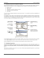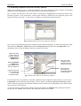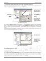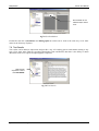
1
BridgeStation v2.0
User Manual
BridgeStation
Advanced Bridge Management System
©Camden Consultancy Service
March 2009
BridgeStation v2.0
User Manual
Table of Contents
1.0 INTRODUCTION ....................................................................................................................................... 1
2.0 INSTALLATION AND DATA MIGRATION................................................................................................... 1
3.0 SYSTEM NAVIGATION .............................................................................................................................. 1
3.1
3.2
3.3
3.4
NAVIGATING FROM THE MAIN MENU......................................................................................................................... 1
NAVIGATION USING THE TOOLBAR AND MENU BAR....................................................................................................... 1
OPENING A STRUCTURE – STEP BY STEP ................................................................................................................... 2
ADDING A NEW STRUCTURE – STEP BY STEP .............................................................................................................. 2
4.0 STRUCTURES AND COMPONENTS ............................................................................................................ 5
4.1 STRUCTURES ..................................................................................................................................................... 5
4.2 COMPONENTS .................................................................................................................................................... 5
5.0 THE INVENTORY EXPLORER..................................................................................................................... 6
5.1
5.2
5.3
5.4
5.5
5.6
5.7
5.8
NAVIGATING THE INVENTORY EXPLORER .................................................................................................................... 6
ADDING A NEW COMPONENT TO AN EXISTING STRUCTURE – STEP BY STEP ......................................................................... 6
MOVING AND DELETING COMPONENTS ...................................................................................................................... 7
RECORDING CONSTRUCTION DETAILS ....................................................................................................................... 8
DOCUMENTS AND PHOTOGRAPHS ............................................................................................................................. 8
RESTRICTIONS ................................................................................................................................................... 9
ASSESSMENT RESULTS ....................................................................................................................................... 10
EVENTS.......................................................................................................................................................... 10
7.0 INSPECTIONS......................................................................................................................................... 11
7.1
7.2
7.3
7.4
7.5
7.6
INSPECTION REGIMES AND INSPECTION TYPES .......................................................................................................... 11
ALLOCATING STRUCTURES TO INSPECTION REGIMES ................................................................................................... 12
SCHEDULING INSPECTIONS .................................................................................................................................. 12
ACCESSING INSPECTIONS FROM THE INVENTORY EXPLORER........................................................................................... 14
RECORDING DEFECTS DISCOVERED DURING THE COURSE OF AN INSPECTION ..................................................................... 15
TEST RESULTS ................................................................................................................................................. 16
8.0 MAINTENANCE ....................................................................................................................................... 17
8.1
8.2
8.3
8.4
8.5
8.6
DEFECT CORRECTION......................................................................................................................................... 17
MAINTENANCE PRIORITISATION ............................................................................................................................ 17
SCHEDULED ROUTINE MAINTENANCE ...................................................................................................................... 18
PLANNED PREVENTATIVE MAINTENANCE .................................................................................................................. 18
OUTSTANDING MAINTENANCE .............................................................................................................................. 19
WORK ORDERS ................................................................................................................................................ 19
9.0 PIPE SUBWAYS....................................................................................................................................... 21
9.1
9.2
9.3
9.4
9.5
9.6
9.7
SUMMARY ....................................................................................................................................................... 21
FIELDS IN THE STATUTORY UNDERTAKERS PLANT COMPONENT, GENERAL TAB ................................................................... 21
REGISTER OF FIXED COSTS.................................................................................................................................. 21
REGISTER OF OPENINGS ..................................................................................................................................... 22
REGISTER OF VOLUME CHANGES ........................................................................................................................... 24
PIPE SUBWAY ADMINISTRATION ............................................................................................................................ 24
PIPE SUBWAY REPORTS ...................................................................................................................................... 25
10.0 ABNORMAL LOADS (OPTIONAL FEATURE)........................................................................................... 26
10.1
10.2
10.3
10.3
SUMMARY ...................................................................................................................................................... 26
MANAGING HAULIERS ........................................................................................................................................ 26
MANAGING ABNORMAL LOAD APPLICATIONS ........................................................................................................... 27
ABNORMAL LOAD REPORTS ................................................................................................................................ 29
11.0 BRIDGE CONDITION INDICATORS ...................................................................................................... 30
11.1 INTRODUCTION .............................................................................................................................................. 30
11.2 COMPONENT TYPES ......................................................................................................................................... 30
11.2 COMPONENT GROUPING .................................................................................................................................... 31
©Camden Consultancy Service
March 2009
BridgeStation v2.0
11.3
11.4
11.5
11.6
11.7
User Manual
ENTERING INSPECTION DATA ............................................................................................................................. 32
BCI SCORES – SINGLE STRUCTURE ..................................................................................................................... 32
BCI STOCK CONDITION SCORES ......................................................................................................................... 33
BCI DATA INTEGRITY ...................................................................................................................................... 34
BCI REPORTS ................................................................................................................................................ 34
12.0 REPORTING .......................................................................................................................................... 36
12.1 SUPPLIED REPORTS ......................................................................................................................................... 36
©Camden Consultancy Service
March 2009
BridgeStation v2.0
User Manual
1.0 Introduction
The purpose of this user manual is to provide basic instructions in the use of the BridgeStation System. An
online version of this manual can be accessed by pressing the F1 key.
2.0 Installation
Included on the installation CD is the file Installation Instructions.doc which gives step by step instructions
for installing the system.
3.0 System Navigation
3.1 Navigating from the Main Menu
The diagram below shows the BridgeStation Main Menu. By default, this menu will be displayed on start-up,
or when all other windows within BridgeStation are closed. It is possible to navigate to most areas of the
system from this menu.
Some users may wish to navigate around the system using the Menu Bar or Tool Bar (as discussed in section
3.2). In this case, it is possible to prevent the Main Menu from being displayed by un-checking the tick box
in the bottom left of the menu. To display the menu at any time, choose ‘Display Main Menu’ from the
Window menu, or Press the ‘Show Main Menu’ toolbar button.
3.2 Navigation Using the Toolbar and Menu Bar
The Menu Bar and Tool Bar both appear in the top left of the main BridgeStation window. You can drag the
Tool bar away from this position using the drag-handle on the left, or to hide it by right-clicking on or near it.
Menu Bar
Tool Bar
Show Main Menu
Holding the mouse over any of the Tool bar buttons will display a description of that button.
©Camden Consultancy Service
1
March 2009
BridgeStation v2.0
User Manual
3.3 Opening a Structure – Step by Step
To display a structure in the Inventory Explorer screen, follow the steps outlined below. If you already have
a structure open, it will be possible to open another one without closing the first.
1.
Display the Open Structure dialog box using one of the following methods;
a. Press the Inventory button from the Main Menu
b. Select File → Open from the Menu Bar
c. Press the Open (
2.
) button on the Tool Bar
Use the Open Structure dialog box (as displayed below) to select a structure. Either double-click on the
name, or click once and then press the OK button.
Select List tab to display all
Structures
Click on field headings to
change sort order
Double-click on a structure to open
it or select it and then press OK
Select Filter tab to search
Structures
Enter text in the Value field
and then Press Find to
display matching results
3.4 Adding a New Structure – Step by Step
It is possible to add a new structure to the database using as little as two mouse-clicks. Some users may
prefer to add a structure this way, going back to fill in information at a later date.
It may be more convenient to use the New Structure Wizard to fill in some basic details about the structure
when it is first created. The steps below illustrate how to add a new structure using the wizard. Press Finish
at any stage during the wizard to create a structure using only the information supplied up to that point.
1.
The New Structure Wizard can be displayed using any of the following methods;
a. Press the Inventory button at the Main Menu, followed by the Add… button
b. Select File → New… from the Menu bar
c. Press the New (
2.
) button on the Tool bar
Once the wizard is displayed, select the type of structure you wish to create. Once you have done this,
you may simply press the Finish button to create a blank structure; alternatively press the Next button
to continue with the wizard.
©Camden Consultancy Service
2
March 2009
BridgeStation v2.0
User Manual
From this point on, the wizard will prompt you for information which will vary depending on the
answers you have given previously. For example, the contents of the second wizard screen will depend
on what structure type you chose in the first screen. We will continue on the assumption that you have
chosen the structure type ‘Bridge’.
3.
In the next step, the wizard will ask you for the Name and Reference Number of the structure. The
Reference Number (Identifier) is optional and may include numbers and/or letters and may be amended
at a later date if required.
4.
Step 3 of the wizard will ask for information on routes which are related to the structure. These may be
carried by, crossed by, adjacent to or carried within the structure. You may select several routes from
the list, eg. a carriageway carried by the structure and a railway crossed.
5.
The next step of the wizard will ask you for the name of the routes entered in the previous step. If you
selected more than two routes, the wizard will only ask you for the names of the first two and you will
need to manually enter names for the rest once the structure has been created.
6.
The final piece of information required by the wizard is the number of spans. If the structure has more
than one span, you have the option to either record all spans as a single component, or alternatively,
record them as individual components.
Recording spans as individual components allows for different characteristics to be recorded for each,
ie. length, capacity, structural form, etc. If all the spans are the same or you do not wish to record
detailed information to this level, you may simply record all spans as a single component.
©Camden Consultancy Service
3
March 2009
BridgeStation v2.0
User Manual
Some structures may have several spans of one construction and several of another construction. You
may for example wish to record 5 similar spans as one component and another 3 spans as a different
component (rather than create 8 separate components). For complex structures such as this, you will
need to manually edit the structure once it has been created by the wizard.
7.
Once the wizard has finished asking for information, press the Finish button to create the new structure.
©Camden Consultancy Service
4
March 2009
BridgeStation v2.0
User Manual
4.0 Structures and Components
4.1 Structures
Structures are the principal entities within BridgeStation against which almost all information is recorded.
All structures must be categorised as one of the following 12 types:
•
•
•
•
•
•
•
•
Basement
Bridge
Culvert
Embankment / Cutting
•
•
•
•
Footbridge
Gantry
Mast
Pipe Subway
Pedestrian Subway
Retaining Wall
Tunnel
Vault / Chamber
The type of information recorded against each structure depends partly on its type. Some information (eg.
name, location, etc.) is recorded for all types. Other information however is only recorded for certain
structure types (eg. Form of Deck is only recorded for bridges and footbridges).
4.2 Components
Once a structure has been created, it is possible to add more detailed
information by specifying components. You may wish to record a
structure with no components, a few basic components, or a hierarchy
of many components.
BridgeStation contains 53 component types which may be added to any
type of structure.
The diagram to the right gives an example of how a structure may be
recorded. A great deal of information about the structure can be
obtained from this diagram alone.
For example, we can see that the structure carries a carriageway (Smith
Street) and has two spans. One span crosses a railway (the District Line)
and the other crosses another carriageway.
Specific information has been recorded in relation to street lighting both
on and below the structure, the bridge parapets (and in particular the
protective coating on the parapets), the deck waterproofing and
structural members, the abutments, the footway and BT cabling running
across the structure.
Listed below are the available component types. The next section details
how these components are displayed and edited.
• Access
Walkway/Gantry
• Abutment / Support
• Access Chamber
• Approach Ramp/Stairs
• Apron
• Arch
• Beam
• Bearing
• Bearing Plinth
• Buckle Plate
• Carriageway
• Ceiling / Soffit
• Cross Head
•
•
•
•
•
•
•
•
•
•
•
•
•
•
•
•
•
•
•
•
•
•
•
•
•
•
•
•
Deck
Deck Brace/Diaphragm
Drainage
Enclosure
Equipment: CCTV
Equipment: Drainage
Equipment: Elec. Power
Equipment: Electronics
Equipment: Fire Safety
Equipment: Mechanical
Equipment: Ventilation
Fender
Floor
Footway
©Camden Consultancy Service
5
Footway Surfacing
Foundations
Invert
Joint
Lighting
Parapet
Pedestrian Subway
Pier/Column
Pipe Subway
Private Land
Railway
Revetment
River Training
Room / Cupboard
•
•
•
•
•
•
•
•
•
•
•
•
•
Safety Fencing
Section
Signage
Span
Spandrel Wall
Stats
Surface Finishes
Tie Rod
Utility Protection Slab
Wall
Waterproofing
Waterway
Wing / Training Wall
March 2009
BridgeStation
Interim User Manual
5.0 The Inventory Explorer
5.1 Navigating the Inventory Explorer
The Inventory Explorer window (as displayed below) is the primary window for accessing all information
about a particular structure. Each window relates to one structure only. The Structure Name is shown as the
window caption, followed by the Identifier (Structure Number) in square brackets if one has been defined.
Structure Name
and [Identifier]
Click here to hide the
tree-view pane.
Double-click to open
full size photograph.
This is the Summary
tab which may be
displayed by
selecting the
Components folder
in the tree-view.
It displays summary
information which
can be edited
elsewhere.
Click plus signs ( )
on the tree-view to
expose nodes.
(Similar to Windows
Explorer)
Right-click on
tree-view nodes to
display options for
adding new
information.
Selecting nodes in the tree-view
pane (left-click) displays
corresponding information in
the right-hand pane.
The right-hand pane is usually
made up of several pages of
information which can be
navigated using these tabs.
The Inventory Explorer window can be resized by clicking on its border and dragging. It is also possible to
alter the width of the tree-view pane by clicking its right-hand border and dragging either left or right.
5.2 Adding a New Component to an Existing Structure – Step by Step
The diagram below shows how to add a new Component to a Structure. Remember to use the right mouse
button and not the left.
Right-click on
tree-view nodes to
display options for
adding new
information.
Select More
Components to
expand the list.
Components may
be added at the
same level, or
below another
component in the
hierarchy.
Select a
component type
to add (left-click).
©Camden Consultancy Service
6
March 2009
BridgeStation
Interim User Manual
1.
Open the Structure using the Inventory Explorer (see Section 3.3)
2.
Decide where your new component will fit in the component hierarchy. Many components will be at the
top level within the Components folder. If a component is part of, or relates specifically to some other
component (ie. it is a sub-component) you may want to reflect this in your hierarchy.
3.
Right-click on the components folder icon or any of the existing components.
4.
Select Add Component to add your new component at the top level or at the same level as the selected
component. Select Sub-Component to add your new component below the selected component in the
hierarchy.
5.
Select one of the components from the list and left-click to add it. You may need to select More
Components to find the component type you need.
6.
A new node will be created in the tree-view and will become selected. Below is an example of a
Footway component just after it has been created. The Element Name will be selected and you can
immediately type in an alternative name if you wish to. You will notice that the node text in the treeview will change to the new description as you type.
Component name
may be made
more descriptive.
Quantity will
default to 1.
Newly created
component node.
7.
The quantity field will default to 1. You may choose to record several physical components as one
node, with a quantity shown as greater than one. This may be appropriate if all of the components have
the same physical characteristics.
5.3 Moving and Deleting Components
Once a component has been created, it is possible to drag it to another position in the hierarchy. Simply click
on a component node and drag it on top of another component to make it a sub-component. Drag a
component onto the Components Folder to make it a top-level component.
It is also possible to delete a component by right-clicking it and selecting Delete. The component node will
not immediately disappear but instead the description will change to <DELETED>. If the component you
delete has sub-components, these will be deleted as well.
If you mistakenly delete a component, you can right-click on it again and select Undelete.
Once you save the structure, the deleted component(s) will disappear and you will no longer be able to
undelete them.
©Camden Consultancy Service
7
March 2009
BridgeStation
Interim User Manual
5.4 Recording Construction Details
Construction details are usually recorded in the Construction tab of the top level node in the Inventory
Explorer (the ‘Components’ node). The fields shown in this tab will vary depending on the structure type.
Some structures may be made up of several sections, each with a different construction. It is therefore
possible to split the structure using Section components, recording separate construction information for
each section. The same is possible using Span components.
For structures with
several different
constructions,
these will be listed
in the summary
tab at the top
level.
When recording structures with multiple
construction, this box should be checked
for the relevant spans/sections and
unchecked at the top structure level.
For structures with a single construction,
record details at the top level.
Different fields will
be displayed for
different structure
types.
It is also possible to record construction details against Culvert and Tunnel components. Section
components which are placed below these component types will display fields relevant to those components,
rather than fields relevant to the main structure.
5.5 Documents and Photographs
It is possible to store documents and photographs against structures, and against individual components
within each structure.
In the case of both Documents and Photographs, the system records the location of the files on your PC or
file server, but does not create a copy of that file. It is important that the location of these files are not
changed after they are added, as BridgeStation will not be able to locate them if they are. For this
reason, it may be advisable to manually copy photos and documents to a location on your file server which
you know will not be moved, before referencing them in BridgeStation.
©Camden Consultancy Service
8
March 2009
BridgeStation
Interim User Manual
Each structure can be assigned a Main Photo which is displayed on the Summary Tab and on one of the
supplied reports. To assign a main photo to a structure, firstly import a photo into the Photographs tab, and
then check the Component’s Main Photo checkbox.
The Plans tab is available for storing plans and provides thumbnails similar to the Photographs tab. It also
has the facility to assign one plan as being the Main Plan for that structure and another as the Location Plan.
Check this box for one photo to
make it the Main Photo for the
summary tab and report.
When structures are synchronised with the Administration database, thumbnails of the attached photographs
are included in the submission package, but not the actual full size photographs. Details of attached
documents are also included, but not the documents themselves.
5.6 Restrictions
To record restrictions against a structure, right-click on the Restrictions folder, select Add Restriction and
then choose a restriction type. For height, width and weight restrictions, the value of the restriction will
automatically be appended to the node description.
Restrictions
Summary
Restrictions with
a Date Lifted
field before the
current date are
shown as inactive.
For each restriction type, it is possible to record a Date Imposed and Date Lifted. If a Date Lifted has been
entered and it is before the current system date, the restriction will be marked as <Inactive>. Inactive
restrictions are not shown in the Restrictions Summary tab or the main Structure Summary Tab.
©Camden Consultancy Service
9
March 2009
BridgeStation
Interim User Manual
5.7 Assessment Results
To add assessment results, right-click on the Assessment Results folder, select Add Assessment and then
choose an assessment type.
Assessment Date
is a mandatory
field for reporting
requirements.
Assessments may
be grouped
together in folders
if appropriate.
BD21 Initial and
Detailed
Assessments
include results on
up to 2 adjacent
footways
Footway
assessments may
be conducted to a
different level
than carriageway.
It may be appropriate to group assessment results into folders to recognise different assessment schemes, or
assessments conducted on specific sections of the structure. To create an Assessment Group, right click on
the Assessment Results folder and select Add Assessment Group. You may then drag assessments into the
new folder or create new ones in the folder by right-clicking it.
If a structure is made up of several sections ( ), you may wish to associate each Assessment Group with a
particular section. Ensure that section components are saved before attempting to select one in the Section
drop-down box of the Assessment Group form.
5.8 Events
The last folder in the Inventory Explorer is the Events folder. This is a place for recording miscellaneous
information on a structure which may range from general correspondence to specific incidents of damage.
Documents and Photographs may be recorded against each event if required.
As with elsewhere in the Inventory Explorer, new events are created by right-clicking the Events folder.
©Camden Consultancy Service
10
March 2009
BridgeStation
Interim User Manual
7.0 Inspections
7.1 Inspection Regimes and Inspection Types
BridgeStation has the facility to schedule and record different types of inspections. One or more inspection
types may be grouped together into what is termed an Inspection Regime. For example, the Classic Regime is
made up of 3 inspection types, Principal, General and Superficial.
Users can edit existing inspection types and regimes, or add new ones using the Inspections Setup screen as
shown in fig 7.1.
List of Inspection
Regimes. [a]
Details of Selected
Regime. [e]
Inspection Types
within the selected
Regime. [b]
Details of Selected
Type. [f]
Add a new Type
to the selected
Regime. [c]
Add a new
Regime. [d]
fig 7.1 Inspection Setup
Most users will initially use the Classic Regime which is included in the default BridgeStation installation. If
this is the case, it may not be necessary to use the setup screen at all, other than to perhaps change the default
cost of different inspection types.
To edit an inspection type within a regime, firstly select the regime on the left-hand list box [a]. Details of
the regime will appear in section [e] including the regime name and its cycle length. The Classic regime has
a cycle length of 6 years, ie. the time between Principal Inspections. The different inspection types for the
selected regime will appear in the Inspections list box [b].
Selecting different inspection types in list box [b] will display details of that inspection type. The Schedule
field is used to indicate which periods within the regime’s cycle the selected inspection type will be
scheduled. For example the Principal Inspection is scheduled only in year 1. The General Inspection is
scheduled for years 3 and 5 of the cycle, so the value in this field should be ‘3,5’. This is illustrated in the
table below;
Classic Inspection Regime:
Schedule
Yr 1
Principal Inspection
(1)
[PI]
General Inspection
(3,5)
Superficial Inspection
(2,4,6)
Yr 2
Yr 3
Yr 4
[GI]
[SI]
Yr 5
Yr 6
[GI]
[SI]
[SI]
The default cost field in fig 7.1 is used to allocate costs to scheduled inspections for the purpose of
budgeting. Note that it is possible to override the default cost of an inspection type for a given structure (see
fig 7.4), or even for a given inspection (as in fig 7.3).
When scheduling inspections, coloured tags are used to represent each inspection. To change the colour of
the tags associated with each inspection type, use the Red, Green and Blue slider controls to mix colours, and
change the text between Black and White to make it more visible.
©Camden Consultancy Service
11
March 2009
BridgeStation
Interim User Manual
7.2 Allocating Structures to Inspection Regimes
Once Inspection Regimes have been created, you may wish to associate them with structures within the
database, based on a number of criteria. BridgeStation allows regimes to be associated on the basis of;
•
•
•
•
•
Structure Type
Owner Type
Components contained within the structure
Carriageway type and vehicle flow
Asset value
Using the Inspection Regime Allocation screen shown in fig 7.2. it is possible to specify any combination of
the above criteria.
For example you may wish to setup inspections for CCTV equipment in pedestrian subways owned by the
local authority. In this instance, you would select Pedestrian Subway in the first tab, Local authority in the
second tab, and CCTV equipment in the third tab. Only structures matching all three of these criteria would
be selected to appear in the scheduling form for this regime.
Select Inspection
Regime to Allocate.
Check ‘Active’ box on
each tab to use specified
criteria.
Choose tabs to
allocate by different
criteria.
Only structure types
listed in this box will be
selected.
Initially all structure
types appear in
Exclude list.
Use Add and Remove
buttons to move between
Exclude and Include lists.
Press Test to show
which structures
meet the selected
criteria.
fig 7.2 Allocating Structures to Regimes
Use the Active checkbox on each tab to determine whether a given criteria is used. Once the tab is activated,
use the Add and Remove buttons to select which criteria values will result in a structure being selected.
Press the Test button to see a list of structures which match the current selection criteria.
7.3 Scheduling Inspections
Once Inspection Regimes and Types have been set up and Structures have been allocated to regimes, it is
possible to view inspection schedules. Inspection schedules can either be viewed for an individual structure
within the Inventory Explorer window, or for all structures using the Inspection Schedule screen as shown in
fig 7.3.
The inspection schedule screen gives a 12 year view of both actual and planned inspection, 6 years history
and 6 years forecast in advance.
©Camden Consultancy Service
12
March 2009
BridgeStation
Interim User Manual
The Inspection Schedule screen only shows one Inspection Regime at a time, so when opening the screen the
first thing to do is select a Regime to work with. This is done using the combo-box in the top right of the
screen.
Once a Regime has been selected, the schedule will display all structures which match the allocation criteria
specified for that Regime (as discussed in Section 7.2). It will also show all actual and forecast inspections
for that regime.
When opening the schedule for the first time, there will be no inspections shown. To add new inspections
(either actual or planned), right click on a cell, choose Insert and then select the Inspection Type to add.
Depending on which cell you clicked on, either an actual or a forecast inspection will be added. Actual
inspections are shown with rounded ends whilst forecast inspections are rectangular.
Either show full 12
year view, or select
second tab to show
month by month
view of selected
year.
Select Inspection
Regime to schedule.
Right-click an
inspection to delete
or show properties.
Right-click an empty
cell to insert an
inspection.
First half of Year tab
shows actual
inspections whilst
the second half
shows planned
inspections.
Only structures
matching the
selected regime’s
allocation criteria will
be listed.
Inspection
properties sheet.
Use Schedule button
to generate planned
inspections.
fig 7.3 Scheduling Inspections
Once you have added an inspection, hold the mouse over the tag to display the inspection type, exact date
and forecast/actual cost. Right-click the tag to either delete it or display the properties form as shown in the
bottom right of fig 7.3. Changing the date in the properties form may move the tag to a different period.
To move a forecast inspection you can left-click and drag it either left or right. When you release it you will
be asked if you wish to move just the selected inspection, or reschedule all inspections for that structure.
Holding down the Ctrl or Alt keys when dropping the tag will automatically move just the one structure or
all structures respectively. Note: It is not possible to move Actual inspections in this way. To change the date
of an actual inspection, open its properties form and change the date there.
If you scroll down the schedule screen you will notice a Total line below all of the Structure lines. This
displays the total cost of inspections for each period.
Once you have entered the history of Actual inspections for each structure, you may wish for the system to
automatically schedule future inspections. To do this, use the Schedule button at the bottom left of the
schedule screen. BridgeStation will add planned inspections up to a certain date (or 6 years in advance if you
don’t enter a date). Once inspections have been automatically scheduled you can re-arrange them by
dragging them around, deleting some, adding additional inspection or even delete all of them by using the
Schedule button again.
©Camden Consultancy Service
13
March 2009
BridgeStation
Interim User Manual
7.4 Accessing Inspections from the Inventory Explorer
Whilst the scheduling screen is useful for managing an overall inspection regime. Details of individual
inspections are best managed on a per-structure basis via the Inventory Explorer.
Fig 7.4 shows the inspection costs form which is displayed by highlighting the Inspections folder in the
Inventory Explorer. Costs entered here override those entered as default costs for inspection types in the
Inspection Setup screen (fig 7.1), but can be overridden on an individual inspection basis.
fig 7.4 Default Inspection Costs for Specific Structure
Fig 7.5 shows an individual inspection as displayed in the Inventory Explorer. To add a new inspection, right
click either the Planned or Actual folders under the Inspections folder and select New Inspection. You
should then enter at least the Regime and Type, together with a date.
Change the Status
value to move an
inspection between
the Planned and
Actual folders.
Enter the overall
condition of each
element in terms of
Extent and Severity.
Right-click Planned
or Actual folder
under Inspections to
add new inspection.
Component Tree will
mirror components
shown in main
Component Folder.
Add comments,
documents and
photographs relating
to this inspection.
fig 7.5 Inspections Node in the Inventory Explorer
For each inspection it is possible to record the condition of each component in the structure, as set out in the
Components section of the Inventory Explorer. This is done by recording an Extent and Severity together
with a comment if required. Note that the condition entered on this form is independent of any defects which
may be present in the structure.
To enter the results of an Inspection which is listed in the database as Planned, firstly change the status of
the inspection to Actual. This will move the inspection into the correct folder.
©Camden Consultancy Service
14
March 2009
BridgeStation
Interim User Manual
7.5 Recording Defects Discovered During the Course of an Inspection
Defects are displayed in the Inventory Explorer as nodes beneath the Inspection nodes. To add a defect to an
inspection, right-click the Inspection node and select Add Defect.
Use Works Required
check-box to ensure
the defect appears in
Maintenance folder.
Right-click an
Inspection to add a
new Defect or Test
Result.
Choose Category of
defect and then Type
within the selected
category.
Extent, Severity and
Priority are used to
calculate prioritisation
score.
fig 7.6 Main Defect Page
By checking the Works Required check-box in fig 7.6, a copy of the defect will appear in the Maintenance
folder as well as below the Inspection it relates to. Leaving the Date Corrected box blank will ensure that
the defect appears as outstanding maintenance, whilst entering a date will put the defect in maintenance
history.
Information entered in the Ranking section of fig 7.6 is used to calculate the maintenance prioritisation score.
This score is discussed in greater detail in Section 8.
Select component to
which defect relates.
Recommended action
will appear on any
Works Order created
for this defect.
fig 7.7 Defect Location Page
Fig 7.7 shows the second tab of the Defect node. This tab is used for recording the location of the defect, and
the component affected by the defect.
The Recommended Action section will appear on any works order created to correct the defect. This is
discussed further in Section 8.
Fig 7.8 illustrates the Cost Breakdown tab which can be used to build up estimates of the cost of repairing a
defect. The tab has the facility to store both estimated and actual costs. Costs may be listed as one amount or
broken down as required. For example, forecast costs may be broken down by quantity of materials/labour
required, whilst actual costs could be broken down by invoice number.
©Camden Consultancy Service
15
March 2009
BridgeStation
Interim User Manual
Record details of cost
estimate and/or actual
costs.
fig 7.8 Cost Breakdown
Each defect also has a Documents and Photographs tab which can be used in the same way as for other
nodes in the Inventory Explorer.
7.6 Test Results
Test results can be added to inspections and provide a way of recording generic information relating to any
type of test. Only three fields are provided (Description, Date and Details) but there is the ability to attach
documents such as test reports and photographs if required.
Right-click an
Inspection to add a
new Test Result.
fig 7.9 Test Results
©Camden Consultancy Service
16
March 2009
BridgeStation
Interim User Manual
8.0 Maintenance
8.1 Defect Correction
Defects entered as part of an inspection will also appear in the Maintenance section, providing that the
Works Required checkbox has been checked.
It is also possible to add a defect directly into the maintenance section if, for example, it was not discovered
as part of an inspection. To add an outstanding defect, right-click on the Outstanding folder under the
Maintenance folder and choose Add Defect.
Any changes made to the defect from within the Maintenance section will be reflected in the Inspections
section.
Enter a Date
Corrected to move
defect into History
section.
Right-click to add a
new Defect.
Outstanding Defects
listed in order of
priority score.
fig 8.1 Defect Correction
8.2 Maintenance Prioritisation
BridgeStation incorporates a simple method of prioritising maintenance work based on the extent, severity
and priority of defects. Prioritisation scores are appended to the description of outstanding defects as shown
in Fig 8.1 above. These scores are calculated based on ranking information multiplied by specific
weightings. These weightings can be set in the Maintenance Prioritisation Settings screen as shown in Fig
8.2.
Prioritisation
formulae.
Press Re-Score All
to recalculate scores
for existing
maintenance items.
Use the defaults
button to reset
weightings to
original values.
fig 8.2 Maintenance Prioritisation Settings
The formulae used to derive the maintenance score is shown in blue text in Fig 8.2. Users may wish to adjust
the weighing of extent, severity and priority values to reflect their own preferences.
©Camden Consultancy Service
17
March 2009
BridgeStation
Interim User Manual
8.3 Scheduled Routine Maintenance
BridgeStation allows for maintenance to be scheduled on a regular basis for items of a routine nature. Fig 8.3
shows a scheduled maintenance item for painting of steelwork.
Scheduled routine maintenance is added by right-clicking on the Schedules folder within maintenance.
Maintenance
Schedule
Maintenance items
will automatically be
generated at a given
time period after the
completion of the
last similar item.
Automatically
generated item
of scheduled
maintenance
fig 8.3 Scheduled Routine Maintenance
Once a schedule has been added, BridgeStation will create an outstanding maintenance item and place it in
the Outstanding folder (unless the first/next date is after the current date, in which case it will do so when
that date is reached). Once the outstanding maintenance item has been marked as complete, the system will
wait the designated period (2 years in the example above) and then create another outstanding maintenance
item at that time, etc.
A priority score can be assigned to scheduled routine maintenance to determine its position in the
outstanding list when it becomes active.
8.4 Planned Preventative Maintenance
Planned preventative maintenance is work that is identified in the system before it actually becomes
outstanding. It is similar to scheduled routine maintenance, except that it relates to one-off work which is not
repeated on a regular basis. The maintenance work is entered with an activation date set to some time in the
future. When the activation date is reached, the maintenance item moves from the Schedules folder into the
Outstanding folder.
Planned
Preventative
Maintenance
Schedule
Once the
Activation Date
is reached, the
maintenance will
move into the
Outstanding
folder
fig 8.4 Planned Preventative Maintenance
To add Planned Preventative Maintenance to a structure, right-click the Schedules folder below the
Maintenance folder in the Inventory Explorer.
©Camden Consultancy Service
18
March 2009
BridgeStation
Interim User Manual
8.5 Outstanding Maintenance
To view a list of outstanding maintenance across all structures, select Maintenance → View Outstanding
from the Menu Bar, or press the Maintenance button from the Main Menu and then the Outstanding button.
Fig 8.5 below shows the Outstanding Maintenance window.
By default, the list is sorted by maintenance priority score. Clicking on any of the column headings will resort the list accordingly. Double-clicking on any of the maintenance items will open the Inventory Explorer
for the corresponding structure and highlight the appropriate item.
Double-click to
view details of
selected item in
the Inventory
Explorer
Click column
headings to
change sort
order
fig 8.5 Outstanding Maintenance
You should note that maintenance items which have been added to a works order are not shown on the
outstanding list, even if the works order has not been closed. These items are shown as outstanding in the
Inventory Explorer for the structure however, until the works order is closed.
8.6 Work Orders
Works orders are printed instructions to carry out work on maintenance items. A works order may contain
one or more maintenance items which may relate to one or more structures within the database. Once works
orders are closed (completed), the maintenance items they contain are also closed and no longer appear in the
Outstanding folder of the Data Explorer.
Fig 8.6 shows the Works Orders list which is accessed from the maintenance menu. Orders which have not
yet been closed are shown with an Open icon. Use the Add… button to add a new works order.
Works Orders
which have not
been closed are
shown with an
Open icon
Closed Works
Orders cannot
be deleted
fig 8.6 Works Order List
Selecting a works order from the list opens the Works Order window as shown in Fig 8.7. The screen
contains a number of fields to identify and describe the order, several date and costing fields and a list of
maintenance items which are included in the order.
©Camden Consultancy Service
19
March 2009
BridgeStation
Interim User Manual
Clicking the Add… button within the Work Items section brings up a list of outstanding maintenance items
which are not already included on any open works order. Double-click on any item from the list to add it to
the works order.
For maintenance items which have costing information, the forecast cost is carried into the works order and a
total calculated. If the estimated total for the works order is different to the sum of the maintenance items, an
adjustment may be entered in the Adjustment field.
Fill in the Date
Closed to close
the works order Clear the date to
re-open
Once the order is
closed, text
cannot be edited
Use the Adjustment
field if the value of the
Works Order will be
different to the sum of
the maintenance items’
values
Click Add to add
new maintenance
items to an open
works order
fig 8.7 Works Order
To mark the works order as closed, enter a date in the Date Closed field. This will record the maintenance
items as complete and prevent the works order from being edited further. Clearing the date closed field will
re-open the works order.
fig 8.8 Printing a Works Order
Press the Print… button to open the Works Order report. This report can also be accessed from the reports
menu. The report is initially opened in preview mode. Press the printer icon to send the report to the default
printer, or select File → Print for more options.
©Camden Consultancy Service
20
March 2009
BridgeStation
Interim User Manual
9.0 Pipe Subways
9.1 Summary
BridgeStation records details of how each subway is used so as to manage the charging of utilities for their
use of the subway.
•
•
•
•
•
A register of fixed costs is included for each Pipe Subway (PS) structure.
Total volume and access volume fields are recorded for PS structures.
A register is kept of cable volume changes.
A register is kept of PS openings.
Utility and contractor invoices can be generated.
9.2 Fields in the Statutory Undertakers Plant Component, General Tab
The following screen shows fields for the ‘stats’ inventory component.
Fig 9.1 Statutory Undertakers Plant Component changes.
Provision exists to record the utility that owns the plant, the start and end point of the plant and volume
details. Note that for the access volume to be used for calculating invoices, it must also be recorded under
the ‘Use and Access’ section (see below.) It is not necessary to create a ‘Statutory Undertakers Plant’
component for each user of the subway in order to create invoices and reports. These fields simply allow a
greater level of detail about the plant if it is required by the user.
9.3 Register of Fixed Costs
The register of fixed costs is located in the ‘Use and Access’ folder of each Pipe Subway, under the ‘Fixed
Costs’ tab.
©Camden Consultancy Service
21
March 2009
BridgeStation
Interim User Manual
Fig 9.2 Fixed Costs Register.
To add a fixed cost, enter information in the fields above the grid and then press ‘+’. Entries in the grid may
be edited by clicking on a cell and typing over them. Entries can be deleted by right-clicking your mouse
when on the relevant row and selecting ‘Delete row’.
The ‘From’ and ‘To’ date fields are important. For any particular line entered on this screen the dates should
be wholly contained within the required reporting period. For instance, if the amounts relate to costs
incurred in the first half of 2003 then they should be entered as being between ‘01/04/2003’ and
‘30/09/2003’ or any shorter period within that range. If an amount is entered over a longer period than the
desired reporting period then it will be ignored! A new line must be created for each item and each reporting
period. In the example above, the Management cost has been entered correctly for the first half of 2001, the
second half of 2001 and the first half of 2002. Additionally, incomplete rows are not saved.
9.4 Register of Openings
The register of openings is located in the ‘Use and Access’ folder of each Pipe Subway, under the
‘Openings’ tab.
Fig 9.3 Register of Openings.
©Camden Consultancy Service
22
March 2009
BridgeStation
Interim User Manual
To register an opening, enter information in the fields above the grid and then press ‘+’. Entries in the grid
may be edited by clicking on a cell and typing. Entries can be deleted by right-clicking your mouse when on
the relevant row and selecting ‘Delete row’.
When a utility is selected, the Contact Name and Telephone fields are automatically populated with default
information stored in the utility; you can change this information simply by typing over it. To change what
default names and phone numbers appear, you need edit the utility (see section 9.4.1 below).
Selecting a PSS value will also automatically fill in the cost field. The default amounts used for each PSS
value can be changed by pressing the ‘Edit PSS Charge’ button.
Managing Utilities and Contractors
The list of utilities and contractors available in the ‘Utility’ drop downs can be edited by pressing the
‘Manage Utilities’ button. This will display the ‘manage utilities’ form from where you can add, edit (by
double clicking) and delete utilities:
Fig 9.4 List of Utility Companies.
Adding and editing utilities invokes the Add/ Edit Utility form, where you can enter name, Address and
default contact information.
Fig 9.4 Editing a utility.
©Camden Consultancy Service
23
March 2009
BridgeStation
Interim User Manual
The check box at the bottom of the form allows you to indicate whether the utility owns any plant within a
subway or if the utility merely does work on behalf of other plant owners.
9.5 Register of Volume Changes
The register of volume changes is located in the ‘Use and Access’ folder of each Pipe Subway, under the
‘Volume Changes’ tab:
Fig 9.5 Register of Volume Changes.
To record a volume change, enter information in the fields above the grid and then press ‘+’. Entries in the
grid may be edited by clicking on a cell and typing. Entries can be deleted by right-clicking your mouse
when on the relevant row and selecting ‘Delete row’.
The volume used for generating invoices will be the volume recorded at the beginning of the invoicing
period. If the volume used by a utility does not change then there is no need to create a new record in this
section. Volume changes registered in the middle of an invoicing period will be ignored until the next
period.
You can make change to the Utilities list by pressing the ‘Manage Utilities’ button (see section 9.4.1 above).
9.6 Pipe Subway Administration
The administration menu is located in the ‘Use and Access’ folder of each Pipe Subway, under the ‘Admin’
tab. From this menu you can access the forms to manage utilities and change the default PSS opening
charges as described above. You can also access the template which is used to change some of the data
included on the invoice letters such as the WCC address and the responsible officers.
Please note that all of the data edited from the administration menu is common to all pipe subways. For
instance, if you add a utility while editing a particular structure then all pipe subways will be able to use the
new utility.
©Camden Consultancy Service
24
March 2009
BridgeStation
Interim User Manual
Fig 9.6 Invoice Letter Template.
Important information used in the invoice letters can be edited by changing data in the text boxes as shown
above. Pressing OK will save any changes made.
9.7 Pipe Subway Reports
The following reports have been added to the system to complement the changes made to the Pipe Subway
components that have been described above.
•
•
•
•
•
•
PS-1, Register of Pipe Subway Openings grouped by Structure. Displays a list of the openings made
in each pipe subway structure for a selected date range.
PS-2, Register of Pipe Subway Openings grouped by Utility. Displays a list of openings made by
each utility for a given date range.
PS-3, Pipe Subway Maintenance Charges. Gives a detailed breakdown of the user and access
volumes and charges for each structure over a given period.
PS-4, Invoice letter. This report generates invoices for all users of the pipe subways for a given
period of time.
PS-5, Summary of Pipe Subway Openings. Shows for any given financial year the number of
openings that each utility made in each month for each PSS category.
PS-6, Summary of Pipe Subway Opening Costs. Same as PS-5 except that the costs are shown
rather than the number of openings
©Camden Consultancy Service
25
March 2009
BridgeStation
Interim User Manual
10.0 Abnormal Loads (optional feature)
10.1 Summary
The following functionality exists within BridgeStation to aid in management of abnormal load traffic.
•
•
•
Abnormal Load applications are recorded
Details of hauliers are recorded
Authorisation letters can be generated
10.2 Managing Hauliers
Click on the Maintenance menu and select the Hauliers item. This will invoke the ‘Manage Hauliers’ form,
form where you can add, edit and delete hauliers:
Fig 10.1 List of Hauliers.
To add a haulier, press ‘Add’. To delete a haulier, select the relevant haulier and press ‘Delete’.
When an indemnity is received BridgeStation can generate a letter to acknowledge the receipt and approval
of the block indemnity. The ‘Edit Letter Template’ button lets you edit key pieces of information that are
included in the letter.
To view or edit a haulier, double-click the relevant haulier or press ‘Edit’. Doing so will invoke the ‘Add /
Edit Haulier’ form shown below. You can use this to edit the haulier details and to add records of block
indemnities when they are received.
©Camden Consultancy Service
26
March 2009
BridgeStation
Interim User Manual
Fig 10.2 Editing a Haulier and adding a block indemnity.
Using this form you can enter Company Name, address, contact fax and general comments.
You can also add block indemnity periods to the haulier using the ‘Block Indemnities’ section. To record a
new block indemnity, enter information in the fields above the grid and then press ‘+’. Entries in the grid
may be edited by clicking on a cell. Entries can be deleted by right-clicking your mouse when on the relevant
row and selecting ‘Delete row’.
Block indemnity information entered on this form is used by Bridgestation to check if Abnormal Load
applications are valid (see section 11.3 below).
10.3 Managing Abnormal Load Applications
Click on the ‘Maintenance’ menu and select the ‘Abnormal Loads’ item. This will invoke the ‘Abnormal
Load Applications’ form, form where you can add, edit and delete Abnormal Load Applications.
Fig 10.3 List of Abnormal Load Applications.
Applications shown with a tick on the icon are those which have been approved.
©Camden Consultancy Service
27
March 2009
BridgeStation
Interim User Manual
To add an application, press ‘Add’. To delete an application, select the relevant item in the list and press
‘Delete’. Items in the list that have been approved have pictures (to the left of the item) with a tick.
Unapproved items do not.
When a movement application is received BridgeStation can generate a letter to acknowledge the receipt and
approval of the movement. The ‘Edit Letter Template’ button lets you edit key pieces of information that are
included in this letter.
To view or edit an application, double-click the relevant haulier. Doing so will invoke the ‘Add / Edit
Abnormal Load Application’ form:
Fig 10.4 Editing an Abnormal Load Application.
Following is a description of each field:
Identification
Application No: When adding a new application, you must enter a unique numeric application number. If the
number already exists in the system, a dialogue box will alert you, and ask you to choose another number.
Their Ref: Hauliers may have their own reference for the application. Record this here.
Received: date received.
Late: Check this box if the application was received late.
Mail Ref: This is the internal mail register reference number, relating to the approval letter for this
application
Haulier & Indemnity Details
Haulier: To assign a haulier to the application, choose an item in the ‘Haulier’ drop down list. Once chosen,
contact details for the haulier (if any have been entered) will appear on the form.
Short term indemnity exists for this move: Some hauliers only provide indemnity for the period of the move.
Tick this box if that is the case for this application. Doing so will automatically validate the application for
indemnity.
©Camden Consultancy Service
28
March 2009
BridgeStation
Interim User Manual
Approval Status
Date of Movement: Enter the relevant from and to dates.
Once the movement dates have been entered, Bridgestation will either:
(1) validate the movement period against the block indemnity cover and return one of three results:
• The haulier has indemnity cover for the period of this move. You will be able to approve this
application.
• Either the Haulier's indemnity dates or the movement dates are incomplete. You will not be able
to approve this application (unless previously approved). You will need to open the Haulier and
check that all date ranges in its Block indemnity cover have ‘From’ and ‘To’ dates entered. You
will not be able to approve this application.
• The haulier does not have sufficient indemnity cover. You will not be able to approve this
application (unless previously approved). You will not be able to approve this application.
(2)
If the ‘Short term indemnity exists for this move’ box has been ticked, the application will be
validated and you will be able to approve it.
Approved: Tick this to approve the application
Approval Confirmation Sent: Fill in the date the acceptance was submitted to the haulier.
Details of Movement
Enter a description of the route to be taken. Details for each load can then be stored in the grid.
Enter the information in the text boxes above the grid and add the load using the ‘+’ button. Rows can be
deleted by selecting one with a right mouse button click and selecting ‘Delete Row.’
10.3 Abnormal Load Reports
The following reports have been added to BridgeStation to assist with the management of Abnormal Loads:
•
•
•
•
•
AL-1 Abnormal Load Applications. Lists all the applications that have been received during a given
date range.
AL-2 Indemnities Received. Lists all the block indemnity notices that have been received during a
given date range.
AL-3 Abnormal Load Summary Report. Summarises the number of indemnities received and
abnormal load applications made for each month of a given financial year.
ALL-1 Acknowledgement of Block Indemnity Letter. Generates a letter to acknowledge the receipt
and approval of a block indemnity from a Haulier. Each letter can be selected by its mail reference
number.
ALL-2 Approval of Abnormal Load Letter. Generates a letter to grant approval to a haulier to allow
the passage of an abnormal load. Each letter can be selected by its mail reference number.
©Camden Consultancy Service
29
March 2009
BridgeStation
Interim User Manual
11.0 Bridge Condition Indicators
11.1 Introduction
The CSS Engineering Committee (Bridges Group) commissioned Atkins Consultants Ltd to develop a
generic methodology for the inspection, recording, scoring and reporting on the condition of structures.
While the focus was on bridges the methodology that was decided on can be used on many types of
structures. This methodology is described in detail in the Atkins publication “Bridge Condition Indicators”
issued in April 2002. It is assumed that the reader is familiar with the contents of the Atkins report.
Modifications have been made to BridgeStation so that users can record details of inspections made using the
Atkins method and prepare reports on the condition of individual structures or a group of structures. The
formulae and calculation methods used by BridgeStation have been based entirely on the recommendations
of the report with clarification sought from Atkins Consultants where necessary.
Note that the following discussion will mainly refer to Bridges but the code will work for all types of
structure. There are special requirements for retaining walls as discussed in the Atkins report however this is
handled automatically by BridgeStation.
11.2 Component Types
The Atkins inspection method breaks a bridge down into 38 different ‘elements’ (the equivalent of a
BridgeStation ‘component’) of which 34 are used for determining the overall condition score of the bridge.
Each different element has a different importance factor so it is important when recording an inspection that
the correct element type is used.
The differing number of component types between BridgeStation and the Atkins inspection regime only
causes some minor issues for the user. While most of the component type names match closely there are
some that have different names and there are also some that do not match to the same level of detail in
BridgeStation. This does not prevent BridgeStation from correctly recording or calculating a bridge
condition, as long as the following table is used when creating a structure in BridgeStation.
Item No.
1
2
3
4
5
6
7
8
9
10
11
12
13
14
15
16
17
18
19
20
21
22
23
Atkins Element
Primary Deck Element
Transverse Beams
Secondary Deck Elements
Half Joints
Tie Rod
Parapet beam or cantilever
Deck bracing
Foundations
Abutments
Spandrel wall/head wall
Pier/column
Cross head/capping beam
Bearings
Bearing plinth/shelf
Superstructure Drainage
Substructure Drainage
Water proofing
Movement/expansion Joint
Painting: deck elements
Painting: substructure elements
Painting: parapets/safety fences
Access/walkways/gantries
Handrail/parapets/safety fences
©Camden Consultancy Service
BridgeStation Component
Main Member *
Secondary Member
Secondary Member
Half Joint
Tie Rod
Secondary Member
Deck Bracing / Diaphragm
Foundations
Abutment / Support
Spandrel Wall
Pier / Column
Cross Head
Bearing
Bearing Plinth / Shelf
Drainage
Drainage
Waterproofing
Joint
Surface Finishes
Surface Finishes
Surface Finishes
Access Walkway / Gantry
Safety Fencing or Parapet
30
Importance
Very High
Very High
Very High
Very High
Very High
Very High
High
High
High
High
Very High
Very High
High
Medium
Medium
Medium
Medium
High
Medium
Medium
Medium
Medium
High
March 2009
BridgeStation
24
25
26
27
28
29
30
31
32
33
34
Interim User Manual
Carriageway surfacing
Footway/verge/footbridge surfacing
Invert/river bed
Aprons
Fenders/cutwaters/collision protection
River training works
Revetment/batter paving
Wing walls
Retaining walls
Embankments
Machinery
Carriageway
Footway Surfacing
Waterway
Apron
Fender
River Training
Revetment / Batter Paving
Wing / Training Wall
Retaining Wall
Embankment / Cutting
Equipment: Mechanical
Medium
Low
Medium
Medium
Medium
Medium
Low
High
Medium
Low
Medium
*Note: You can also use the ‘Deck’ component for Item 1. See comments below.
Table 11.1 BridgeStation and Atkins component type comparison..
All other components in BridgeStation have no importance as far as the bridge condition scoring is
concerned and including them in the structure tree will not affect the condition score
There is one exception to the above table. If you choose to inspect all of the deck elements as a single entity
or if you want to use the ‘Deck’ component in place of ‘Main Member’ for the Primary Deck Element
(Atkins No 1 element) then you can force the ‘Deck’ component to be included in the BCI calculations by
ticking the checkbox on the Deck component, ‘General’ tab, as shown in Fig 11.1 below. If this option is
used then you should not also include a ‘Main Member’ component in you inspection as this will result in the
weighting of these very high importance elements to be reduced with regard to the structure as a whole.
Enter a Deck
Area to allow
scores to be
properly weighted.
Tick this box to
include the Deck
component in the
BCI calculation.
Fig 11.1 BridgeStation Deck Element.
11.2 Component Grouping
If a structure includes multiple spans then BridgeStation will calculate the scores of each span and then
weight them in order to calculate a score for the bridge as a whole. If more than one span exists on a
structure then the weighting will be performed according to the following rules:
• If every span has a ‘Deck’ component and every deck component has a deck area entered then the
spans will be weighted by deck area. Note that the ‘Deck’ component does not have to be included
in the BCI calculation (with the check box ticked as discussed in the previous section) it simply
needs to be there as a way of letting BridgeStation know what the deck area of the span is.
©Camden Consultancy Service
31
March 2009
BridgeStation
•
•
•
Interim User Manual
If any of the spans is missing a ‘Deck’ component or any of the ‘Deck’ components does not have a
value in the ‘Area’ field then the score for each span will be calculated and a simple average will be
used to calculate the combined Bridge score.
Any components that are not included under a span where a bridge has multiple spans will be
weighted as though they belong to the whole bridge. For example, if a bridge has 5 spans but a
parapet is included as a single item outside of any of the spans, then the parapet will be weighted
either with the total deck area of the bridge (if area is used) or with a weighting of 5 if a simple
average is used.
The above weightings only apply to the average condition score. The critical condition score is
taken from the very high importance component with the worst condition score from the whole
structure, as detailed in the Atkins report.
11.3 Entering Inspection Data
Inspection results can be entered into the system in the usual manner as described in Section 7.4 of this
manual.
Components that are not inspected (because they are obscured, overgrown, etc) can have this recorded by
selecting ‘NI: Component was Not Inspected’ in the extent column. If an inspection result is not applicable
for an element in the tree (eg the ‘Span’ in figure 11.2 below) then it can be left blank.
Fig 12.2 Entering Inspection Data.
You can enter inspection information for component types not listed in Table 11.1 without affecting the
condition score calculation. All components that do not have an importance factor are ignored when
calculating the condition scores.
11.4 BCI Scores – Single Structure
The bride condition scores for an individual structure can be seen by selecting the “BCI” tab which is
available when the “Components” folder is selected. The screen gives you the option to select any
inspection which has been carried out and will display the scores obtained as a result of that inspection. If a
new inspection is added or inspection results changed then the data can be refreshed by pressing the
‘Refresh’ button.
©Camden Consultancy Service
32
March 2009
BridgeStation
Interim User Manual
Select the
inspection
you want to
report on.
The default is
the most
recent.
Check to get
scores weighted
on the deck area
of the spans.
BridgeStation will
notify if there is
missing data.
A list of
components
and their
Element
Condition
Score will be
displayed.
Fig 11.3 BCI Scores showing detail and summary data.
If your structure has inspection data completed then the screen should appear similar to the image above. All
of the components in the component tree which have an importance factor and valid inspection data will be
displayed in the list of Element Condition Scores. This list shows the importance factor used, the extent and
severity data from the chosen inspection and the Element Condition Index that is obtained using this data.
In the top right hand section of the screen there is a summary of the Average and Critical Bridge Condition
Scores and Indexes that are obtained using the data shown in the list. These are calculated using the
formulae contained in the Atkins report. There is also an option to select whether the scores should be
weighted by span area if there is a multi span bridge. If there are no spans in the structure then selecting this
option has no effect. If there are spans in the structure tree then BridgeStation will use them in the weighting
calculations, using the deck area to weight if all spans have deck area information or a simple average if not.
If a simple average is used (due to missing deck area data) then a message will be displayed below the
scores.
Choosing to weight by spans can affect the resulting scores even if the structure only contains one span.
This is because weighting by spans causes results from the components under the span to be calculated first
and then the span is treated as a single entity with that score. Any components not associated with a span
also have their scores calculated and the resulting score is then averaged with the score of the span. This can
give a different result to simply averaging the scores of all the components together.
11.5 BCI Stock Condition Scores
In addition to calculating scores for an individual structure it is possible to report the condition of the entire
stock of structures or of a selected group of structures (eg bridges, subways.) To view the scores, select the
‘Stock Condition’ item from the ‘Inspections’ menu on the main menu bar (see figure below.) This will
open the Condition Indicators window.
Select the type of structure you wish to report on. You can select multiple items by holding the <Ctrl> key
down while clicking items with the mouse. You can also select whether you want BridgeStation to weight
the scores by spans (where applicable) or if all components within a structure are weighted equally. The
scores would normally be calculated with the ‘Weight scores by spans’ option selected. If BridgeStation is
unable to use the deck area of structures to assist with the weighting then this will be reported as shown
below.
©Camden Consultancy Service
33
March 2009
BridgeStation
Interim User Manual
Check to get
scores weighted
on the deck area
of the spans.
BridgeStation will
notify if there is
missing data.
Select the structure
type(s) to be
reported on.
Notification area indicates if deck
area is used in
calculations.
Indicates number of
valid vs total
structures of the
selected type.
Fig 11.4 BCI Stock Condition Scores.
After a calculation has been run there is a display which shows how many structures were used in the
calculation compared to how many structures exist in the selected structure types. The main reason for
structures not being included is that they do not have a completed inspection.
11.6 BCI Data Integrity
In order to get an accurate picture of the condition of a bridge (or other structure) stock it is important to
ensure that the structures have all been correctly entered into BridgeStation and that valid (and thorough)
inspection data is available for all components.
There are some reports provided to help the user determine the quality of the data. These are all available
through the normal reporting menu, under the reports category ‘Condition Indicators.’
•
•
•
•
DI-1 Histogram showing the frequency distribution of components per structure. This report gives a
feel for how well populated the inventory is with regard to structures being described in sufficient
detail. Generally speaking most types of structures should have five or more components being
inspected.
DI-2 Histogram showing the frequency distribution of the number of inspected components in a
structure. Similar to the above but this also indicates how many of the components have valid
inspection data.
DI-3 Missing data report. Shows Bridges with no deck components, retaining walls with no length
information etc. This sort of data is not vital in order to produce reports however it will prevent
structures having their scores being properly weighted (eg by deck area for bridges.)
DI-4 Missing inspection data. Shows all those structures (excluding retaining walls) that have
inspections but where the inspection does not include a score for at least 1 component of very high
importance.
11.7 BCI Reports
Reports showing BCI scores and histograms can be accessed through the reports menu in the ‘Condition
Indicators’ section. The reports can be prepared for the entire database, for types of structures and also for
individual structures.
•
CI-1 Structure Listing. A listing of the selected types of structures with the BCI scores of each
structure. The report also includes a histogram showing the distribution of the scores listed.
©Camden Consultancy Service
34
March 2009
BridgeStation
•
•
•
Interim User Manual
CI-2 Condition by Database ID (Admin Version Only)
CI-3 Structure Detail. Shows a detailed calculation of the score for each structure. This would
normally only be run for a single structure but it can be run for a structure type or all structures.
CI-4 Histogram of Condition Scores. Shows the frequency distribution of condition scores for all
structures or a type of structures. The same as the histogram at the tail of CI-1.
©Camden Consultancy Service
35
March 2009
BridgeStation
Interim User Manual
12.0 Reporting
12.1 Supplied Reports
Access the Reports menu from the Main Menu, the Menu Bar (Tools → Reports) or using the Tool bar
button ( ). A number of pre-written reports are available to choose from. Sample reports are included in
Appendix A.
To limit the
records returned,
choose one or
more filter criteria
To run a report,
firstly select a
Category
Once you have
chosen a filter
criteria, choose a
filter value
Some reports
have different
versions to select
Fig 12.1 Reports Screen
To display a report firstly select an item from the Category box, and then choose from the Version box if
there is more than one listed.
You may also want to limit the records to be included in the report by implementing a filter. Choose a field
from the Filter Criteria drop-down menu and then select one of the values which appear below it.
Press OK to run the report. BridgeStation will open up a MS Access database called BridgeReports.mdb and
will display your report. Once the report is displayed you can choose to print it using the standard Access
report options. Closing the report will also close the Access database.
Report Version
Identifier
Press the print
icon to send the
report to the
default printer
Criteria Expression
Fig 12.2 Sample Report
©Camden Consultancy Service
36
March 2009