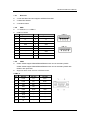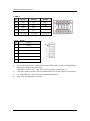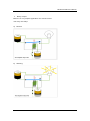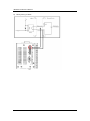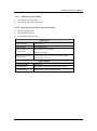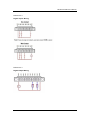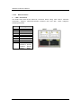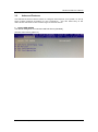
1
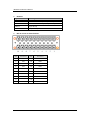
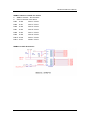
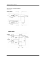
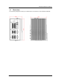
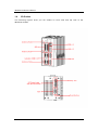
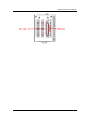
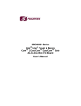
rBOX510-6COM Robust Din-rail Fanless Embedded System User’s Manual Disclaimers This manual has been carefully checked and believed to contain accurate information. Axiomtek Co., Ltd. assumes no responsibility for any infringements of patents or any third party’s rights, and any liability arising from such use. Axiomtek does not warrant or assume any legal liability or responsibility for the accuracy, completeness or usefulness of any information in this document. Axiomtek does not make any commitment to update the information in this manual. Axiomtek reserves the right to change or revise this document and/or product at any time without notice. No part of this document may be reproduced, stored in a retrieval system, or transmitted, in any form or by any means, electronic, mechanical, photocopying, recording, or otherwise, without the prior written permission of Axiomtek Co., Ltd. Copyright 2015 Axiomtek Co., Ltd. All Rights Reserved October 2015, Version A3 Printed in Taiwan ii Safety Precautions Before getting started, please read the following important safety precautions. 1. The rBOX510-6COM does not come equipped with an operating system. An operating system must be loaded first before installing any software into the computer. 2. Be sure to ground yourself to prevent static charge when installing the internal components. Use a grounding wrist strap and place all electronic components in any static-shielded devices. Most electronic components are sensitive to static electrical charge. 3. Disconnect the power cord from the rBOX510-6COM before making any installation. Be sure both the system and the external devices are turned OFF. Sudden surge of power could ruin sensitive components. Make sure the rBOX510-6COM is properly grounded. 4. Make sure the voltage of the power source is correct before connecting the equipment to the power outlet. 5. Turn OFF the system power before cleaning. Clean the system using a cloth only. Do not spray any liquid cleaner directly onto the screen. 6. Do not leave this equipment in an uncontrolled environment where the storage temperature is below -45℃ or above 85℃. It may damage the equipment. 7. Do not open the system’s back cover. If opening the cover for maintenance is a must, only a trained technician is allowed to do so. Integrated circuits on computer boards are sensitive to static electricity. To avoid damaging chips from electrostatic discharge, observe th e following precautions: Before handling a board or integrated circuit, touch an unpainted portion of the system unit chassis for a few seconds. This will help to discharge any static electricity on your body. When handling boards and components, wear a wr ist-grounding strap, available from most electronic component stores . iii Classification 1. Degree of production against electric shock: not classified 2. Degree of protection against the ingress of water: IP30 3. Equipment not suitable for use in the presence of a flammable anesthetic mixture with air or with oxygen or nitrous oxide. 4. Mode of operation: Continuous 5. Type of protection against electric shock: Class I equipment General Cleaning Tips You may need the following precautions before you begin to clean the computer . When you clean any single part or component for the com puter, please read and understand the details below fully. When you need to clean the device, please rub it with a piece of dry cloth. 1. Be cautious of the tiny removable components when you use a vacuum cleaner to absorb the dirt on the floor. 2. Turn the system off before you start to clean up the component or computer. 3. Never drop the components inside the computer or g et circuit board damp or wet. 4. Be cautious of all kinds of cleaning solvents or chemicals when you use it for the sake of cleaning. Some individuals may be allergic to the ingredients. 5. Try not to put any food, drink or cigarette around the computer. iv Cleaning Tools Although many companies have created products to help improve the process of cleaning your computer and peripherals users can also use household items to clean their computers and peripherals. Below is a listing of items you may need or want to use while cleaning your computer or computer peripherals. Keep in mind that some components in your computer may only be able to be cleaned using a product designed for cleaning that component, if this is the case it will be mentioned in the cleaning. Cloth: A piece of cloth is the best tool to use when rubbing up a component. Although paper towels or tissues can be used on most hardware as well, we still recommend you to rub it with a piece of cloth. Water or rubbing alcohol: You may moisten a piece of cloth a bit with some water or rubbing alcohol and rub it on the computer. Unknown solvents may be harmful to the plastics parts. Vacuum cleaner: Absorb the dust, dirt, hair, cigarette particles, and other particles out of a computer can be one of the bes t methods of cleaning a computer. Over time these items can restrict the airflow in a computer and cause circuitry to corrode. Cotton swabs: Cotton swaps moistened with rubbing alcohol or water are excellent tools for wiping hard to reach areas in your key board, mouse, and other locations. Foam swabs: Whenever possible it is better to use lint free swabs such as foam swabs. Note: We strongly recommended that you should shut down the system before you start to clean any single components. Please follow the steps below: 1. Close all application programs 2. Close operating software 3. Turn off power 4. Remove all device 5. Pull out power cable v Scrap Computer Recycling If the computer equipments need the maintenance or are b eyond repair, we strongly recommended that you should inform your Axiomtek distributor as soon as possible for the suitable solution. For the computers that are no longer useful or no longer working well, please contact your Axiomtek distributor for recycling and we will make the proper arrangement. Trademarks Acknowledgments Axiomtek is a trademark of Axiomtek Co., Ltd. IBM, VGA are trademarks of International Business Machines Corporation. ® Intel is registered trademarks of Intel Corporation. Windows 7, Windows 8 and QuickBASIC are trademarks of Microsoft Corporation. UMC is a trademark of United Microelectronics Corporation.Other brand names and trademarks are the properties and registered brands of their respective owners. vi Table of Contents Safety Precautions ................................................................................................. iii Classification .......................................................................................................... iv General Cleaning Tips ........................................................................................... iv Scrap Computer Recycling ................................................................................... vi CHAPTER 1 INTRODUCTION ................................................................................. 1 1.1 1.2 1.2.1 1.2.2 1.2.3 1.2.4 1.2.5 1.2.6 1.2.7 1.2.8 1.2.9 1.2.10 1.2.11 1.2.12 1.2.13 1.2.14 1.2.15 1.2.16 1.2.17 1.2.18 1.2.19 1.2.20 1.3 1.4 General Description ............................................................................ 1 System Specifications ........................................................................ 2 CPU .................................................................................................................... 2 BIOS ................................................................................................................... 2 System Memory ................................................................................................ 2 Display ............................................................................................................... 2 Ethernet Ports ................................................................................................... 2 Storages............................................................................................................. 2 Wireless ............................................................................................................. 3 USB .................................................................................................................... 3 COM .................................................................................................................... 3 Power ................................................................................................................. 4 WatchDog Timer (WDT).................................................................................... 7 Digital I/O Connector and Pin Definition ........................................................ 7 Ethernet Ports ................................................................................................. 12 System LED ..................................................................................................... 13 Operation Temperature .................................................................................. 14 Storage Temperature ...................................................................................... 14 Humidity........................................................................................................... 14 Weight .............................................................................................................. 14 Dimensions...................................................................................................... 14 System I/O Outlets .......................................................................................... 14 Dimensions ....................................................................................... 15 I/O Outlets.......................................................................................... 16 CHAPTER 2 HARDWARE INSTALLATION........................................................ 19 2.1 2.2 2.3 2.4 2.5 Installing the Hard Disk Drive .......................................................... 19 Installing the Wireless module ......................................................... 21 Installing the mSATA module........................................................... 27 Installing Din-rail Mounting .............................................................. 28 Installing Wall Mounting (optional) .................................................. 30 CHAPTER 3 AMI UEFI BIOS UTILITY ................................................................. 31 3.1 3.2 3.3 3.4 3.5 3.6 3.7 Entering Setup .................................................................................. 31 The Main Menu .................................................................................. 32 Advanced Features ........................................................................... 33 Chipset Feature ................................................................................. 42 Security.............................................................................................. 43 Boot Type .......................................................................................... 45 Save & Exit ........................................................................................ 48 APPENDIX A WATCHDOG TIMER ...................................................................... 51 About Watchdog Timer .................................................................................... 51 How to Use Watchdog Timer ........................................................................... 51 vii APPENDIX B DIO Command ................................................................................ 53 How to Use DIO Registers ................................................................................ 53 viii rBOX510-6COM User’s Manual CHAPTER 1 INTRODUCTION This chapter contains general information and detailed specifications of the rBOX510-6COM. The Chapter 1 includes the following sections: General Description System Specification Dimensions I/O Outlets 1.1 General Description rBOX510-6COM Din-rail fanless embedded system is suitable for communications control and for protocol converter applications in critical environments. Built for rugged work environments, rBOX510-6COM features an extra low power ® consumption Intel ATOM ™ E3827 (1.75GHz) processors supporting industrial temperature range of -40℃ to +70℃. Its front accessible I/O cabling is very convenient for wiring and maintenance. rBOX510-6COM offers a VGA output, making it particularly well-suited for communication control, SCADA and industrial automation. Its compact size with Din-rail mounting allows for easy installation into ® control cabinet. Pre-installed with Linux, W indows 7 embedded and Windows 8 embedded, rBOX510-6COM provides programmers with a friendly environment for developing application software at a lower cost. rBOX510-6COM is robust industrial-grade hardware design and adopts the advanced cooling system, besides, supporting the CompactFlash™ and SATA SSD (or HDD), which makes it especially suitable for field control & monitoring system solution for following markets: Utility Industries (Water; Energy; Chemical Plant; Mining…) Public Transportation Industries (Traffic/ Highway Control; Train/Bus Control…) Homeland Security (Weather Monitoring/Alarm System…) Features Fanless design Wide temperature operation of -40℃ - +70℃ Supports 2 10/100/1000 Base-T Ethernets with Magnetic Isolated Protection 4 isolated RS-232/422/485 COM Ports and 2 RS-232/422/485 COM Ports 1 isolated DIO (8-IN/ 8-OUT) 3 Wireless (3G/GPRS & Wifi) Support one 2.5” SATA SSD (or HDD), m-SATA and one CompactFlash™ Wide range 12–48V DC-in with terminal block Din-rail mounting Wall mounting (optional) Passed Heavy Industrial CE, FCC Part 18 and UL testing Passed ATEX & C1D2 Anti-explosive Certification Introduction 1 rBOX510-6COM User’s Manual Embedded O.S. Supported ® ® rBOX510 not only supports Windows 7 and Windows 8, but also supports ® ® embedded OS, such as W indows 7 embedded, W indows 8 embedded and Linux package support. For storage device, rBOX510 supports one SATA SSD (or HDD) and one type II CompactFlash ™ socket. 1.2 System Specifications 1.2.1 ® Onboard Intel ATOM™ E3827 (1.75 GHz) processor. 1.2.2 CPU BIOS AMI (American Megatrends Inc.) UEFI (Unified Extensible Firmware Interface) BIOS. 1.2.3 System Memory Memory down solution w/extended temperature memory chip Memory size 4GB onboard 1.2.4 A slim type 15-pin D-Sub connector as VGA connector. 1.2.5 Display Ethernet Ports LAN 1 and LAN 2 The board has dual RJ-45 connectors, support 10/100/1000Mbps with 1.5KV magnetic isolated protection. Support PXE boot and LAN wake-up 1.2.6 Storages 1 x 2.5” SATA SSD/HDD drive bay selectable ) 1 x CompactFlash TypeII socket (default) or 1 x mSATA socket (by BIOS Note: mSATA and SATA SSD (or HDD) can be either one. Note: mSATA and wireless use the same slot, and only one of them can be selected. 2 Introduction rBOX510-6COM User’s Manual 1.2.7 Wireless 3 x Full size Mini Card slot supports 3G/GPRS and Wifi. 2 x SIM Card Socket. 3 x Antenna holes. 1.2.8 USB 1 x USB2.0 & 1 x USB3.0 USB Pin Define Pin Signal USB 2.0 Pin Signal USB 3.0 1 VCC 1 VCC 2 D- 2 D- 3 D+ 3 D+ 4 GND 4 GND - - 5 SSRX- - - 6 SSRX+ - - 7 GND - - 8 SSTX- - - 9 SSTX+ 1.2.9 USB2.0 USB 3.0 COM COM1~COM2 support RS232/RS422/RS485 which can be selected by BIOS. COM3~COM6 support RS232/RS422/RS485 which can be selected by BIOS with Isolation 2KV protection. Supports Auto Flow Control in RS485 mode. COM1~2 Pin RS-232 RS-422 RS-485 1 DCD TX- Data- 2 RXD TX+ Data+ 3 TXD RX+ -- 4 DTR RX- -- 5 GND GND GND 6 DSR -- -- 7 RTS -- -- 8 CTS -- -- 9 RI -- -- Introduction 3 rBOX510-6COM User’s Manual COM3~6 Pin RS-232 RS-422 RS-485 1,6 RXD TX+ Data+ 2,7 CTS TX- Data- 3,8 TXD RX+ -- 4,9 RTS RX- -- 5,10 1.2.10 ISO_GND ISO_GND ISO_GND Power Pin Signal 1 Alarm+ 2 Alarm- 3 Power Fail 4 Shield Ground 5 GND 6 PWR PF pin must connect to external the power fail of UPS, so can normal shutdown when being abnormal power loss. LVCMOS 3.3 Level, VIL: 0.8V, VIH: 2.0~3.6,system internal pull up. The relay default function will be enabled when the system cannot normal boot One wide-range 12 - 48V DC power input with terminal block. OVP, UVP and Reverse protection. 4 Introduction rBOX510-6COM User’s Manual Relay output Below is a very simple application for remote notice use relay and lamp. a) Normal b) W arning Introduction 5 rBOX510-6COM User’s Manual c) 6 Relay wiring of rBox Introduction rBOX510-6COM User’s Manual 1.2.11 WatchDog Timer (WDT) One step is 1sec, 255 levels One step is 1sec/1min, 255 levels. 1.2.12 Digital I/O Connector and Pin Definition 8bit DI and 8bit DO 3KV optical isolation DIO Design Sepcification Digital Input Input Channels 8,source type Input Voltage 0 to 30VDC Input Digital Input Levels for Dry Contacts Logic level 0:Close to GND. Digital Input Levels for Wet Contacts Logic level 0:+10V to +24V (DI To XIN_COM-). Logic level 1:Open Logic level 1:+3V max. Digital Output Output Channels 8,sink type Output Current Max. 200 mA per channel, current sink type External voltage 10 to 30VDC , open collector to 30V Introduction 7 rBOX510-6COM User’s Manual Remark Signal Name Meaning COM+ Plus common for Input/ Output Group COM- Minus common for Input/Output Group DIN0~7 Input Group DOUT0~7 Output Group 8 DIO 8 in/out of TB20 Female Pin Function Pin Function 1 COM+ 11 COM+ 2 DI0 12 DO0 3 DI1 13 DO1 4 DI2 14 DO2 5 DI3 15 DO3 6 DI4 16 DO4 7 DI5 17 DO5 8 DI6 18 DO6 9 DI7 19 DO7 10 COM- 20 COM- Introduction rBOX510-6COM User’s Manual SMBus Address & GPIO Pin Define SMBus Address : 0b0100100X GPIO schematic PIN define PIN4 DI0 PIN13 DO0 PIN5 DI1 PIN14 DO1 PIN6 DI2 PIN15 DO2 PIN7 DI3 PIN16 DO3 PIN8 DI4 PIN17 DO4 PIN9 DI5 PIN18 DO5 PIN10 DI6 PIN19 DO6 PIN11 DI7 PIN20 DO7 SMBus to GPIO Schematic Introduction 9 rBOX510-6COM User’s Manual DIO operation schematic diagram Reference 1. Reference 2. 10 Introduction rBOX510-6COM User’s Manual Reference 3 Digital Input Wiring Reference 4 Digital Output Wiring Introduction 11 rBOX510-6COM User’s Manual 1.2.13 Ethernet Ports LAN 1 and LAN 2 The board has dual RJ-45 ethernet connector which using Intel I210-IT ethernet controllers, support 1000/100/10-Base transmit rate and with 1.5KV magnetic isolated protection. Pin L1 L2 L3 L4 L5 L6 L7 L8 A B 12 Signal MDI0+ MDI0MDI1+ MDI1MDI2+ MDI2MDI3+ MDI3Active LED Speed LED 1000-Base-T 100-Base-T 10-Base-T (Yellow) (Amber) (Green) (Dark) Introduction rBOX510-6COM User’s Manual 1.2.14 System LED There are showed the LED’s indicators and functional descriptions. LED Name PWR Description Indicate the Power status. LED will be on for green color when the power DC input is acceptable. LED will be on for red color when the power DC input isn’t acceptable or power fail event. The LED for ACT can help user’s to judge BIOS finish or not and the OS can normal work or not. - ACT - LED will ON for red color when the power DC input is system active LED will flash for red color when the BIOS start LED will ON for green color when enter OS status. LED will flash for green color when the storage is accessed. LED always ON without any flash for a long time, the OS is possible crashed. LED is off when system shutdown status Color Green Red Green Red Indicate the Wireless status. Wireless - When ANT accessed data the LED will flash. Green COM TX1 When COM1 transmit data the LED will on. Green COM RX1 When COM1 receive data the LED will on. Yellow COM TX2 When COM2 transmit data the LED will on. Green COM RX2 When COM2 receive data the LED will on. Yellow COM TX3 When COM3 transmit data the LED will on. Green COM RX3 When COM3 receive data the LED will on. Yellow COM TX4 When COM4 transmit data the LED will on. Green COM RX4 When COM4 receive data the LED will on. Yellow COM TX5 When COM5 transmit data the LED will on. Green COM RX5 When COM5 receive data the LED will on. Yellow COM TX6 When COM6 transmit data the LED will on. Green COM RX6 When COM6 receive data the LED will on. Yellow Introduction 13 rBOX510-6COM User’s Manual 1.2.15 -40℃ ~ +70℃ 1.2.16 Dimensions 85.6mm(3.37”) (W) x110mm(4.33”) (D) x155mm(6.10”) (H) 1.2.20 Weight 1.8kg 1.2.19 Humidity 5% ~ 95% (non-condensation) 1.2.18 Storage Temperature -45℃ ~ +85℃ 1.2.17 Operation Temperature System I/O Outlets Two DB9 connectors support RS232/RS422/RS485 (COM1/2) Four isolated Terminal Block connectors support RS232/RS422/RS485 (COM3~COM6) One 15-pin D-Sub female connector for VGA. Two 10/100/1000Mbps RJ-45 with 1.5KV magnetic isolated protection. One isolated DIO (8-IN/8-OUT) One USB 2.0 connector & one USB 3.0 connector One DC Power Input with terminal block. Three Antenna holes. One SIM Card Socket One CompactFlash TypeII socket 14 Introduction rBOX510-6COM User’s Manual 1.3 Dimensions The following diagrams show you dimensions and outlines of the rBOX510-6COM. Introduction 15 rBOX510-6COM User’s Manual 1.4 I/O Outlets The following figures show you I/O outlets on front view and top view of the rBOX510-6COM. 16 Introduction rBOX510-6COM User’s Manual Introduction 17 rBOX510-6COM User’s Manual This page is intentionally left blank. 18 Introduction rBOX510-6COM User’s Manual CHAPTER 2 HARDWARE INSTALLATION The rBOX510-6COM is convenient for your various hardware configurations, such as Hard Disk Drive. The chapter 2 will show you how to install the hardware. It includes: 2.1 Step 1 Installing the Hard Disk Drive Turn off the system. Step 2 Loosen all screws of the cover and remove the cover from the system. Step 3 Take out the SATA+Power HDD cable & 4pcs of screws for fixing the Hard Disk Drive from the accessory bag. Hardware Installation 19 rBOX510-6COM User’s Manual Step 4 Insert the Hard Disk Drive into the bracket and use these screws to fix tightly. Note: The positive of Hard Disk Drive must be upward when insert the Hard Disk Drive into the bracket. Step 5 Connecting the SATA+Power HDD cable with Hard Disk Drive. Step 6 Put the cover back to the system, and fasten screws tight close the chassis. 20 Hardware Installation rBOX510-6COM User’s Manual 2.2 Installing the Wireless module rBOX510-6COM offers 3 solutions to install wireless module as follows: The wireless socket is near heatsink cover side, supports USB/PCIe interface. Two wireless sockets are near SSD cover side, one socket supports mSATA/USB/PCIe interface, another supports USB/PCIe interface only. Note: We strongly recommend to choose the wireless socket near heatsink cover side firstly if user only has one wireless inquiry, because the wireless module can be heat dissipated via the thermal parts directly. Note: mSATA and wireless use the same slot, and only one of them can be selected. Hardware Installation 21 rBOX510-6COM User’s Manual The wireless socket is near heatsink cover side Step 1 Turn off the system. Step 2 Loosen all screws of the cover and remove the cover from the system. Step 3 Take out the thermal pad form the wireless module kit, then stick on the thermal parts. Note: Must use the dedicated option wireless module kit for rBOX510-6COM. 22 Hardware Installation rBOX510-6COM User’s Manual Step 4 Plug the wireless module in the wireless socket and use screws to fix tightly. Step 5 Put the cover back to the system, and fasten screws tight close the chassis. Hardware Installation 23 rBOX510-6COM User’s Manual Step 6 Plug the SIM card into the SIM slot and the positive of SIM Card is as below picture. Step 7 Put the cover for SIM card/CF card to the system, and fasten locked tightly. . 24 Hardware Installation rBOX510-6COM User’s Manual Two wireless sockets are near SSD cover side. Step 1 Turn off the system. Step 2 Loosen all screws of the cover and remove the cover from the system. one socket supports mSATA/USB/PCIe interfa ce Step 3 Plug the wireless module in the wireless socket and use screws to fix tightly. Step 4 Put the cover back to the system, and fasten screws tight close the chassis. Note: The 3G module needs with SIM slot. Hardware Installation 25 rBOX510-6COM User’s Manual another supports USB/PCIe interface only. Step 3 Put the SIM card into the SIM slot firstly. Step 4 Then plug the wireless module in the wireless socket and use screws to fix tightly. Step 5 Put the cover back to the system, and fasten screws tight close the chassis. 26 Hardware Installation rBOX510-6COM User’s Manual 2.3 Installing the mSATA module Step 1 Turn off the system. Step 2 Loosen all screws of the cover and remove the cover from the system. Step 3 Plug the mSATA module in the socket and use screws to fix tightly. Step 4 Put the cover back to the system, and fasten screws tight close the chassis. Note: mSATA and wireless use the same slot, and only one of them can be selected. Hardware Installation 27 rBOX510-6COM User’s Manual 2.4 Installing Din-rail Mounting The rBOX provides Din-rail Mount that customers can install as below: Step 1 Prepare Din-rail Mount assembling components (screws and bracket) ready. Step 2 Assembly the bracket to the system, and fasten screws tight. Note: Please notice the Din-rail holes with Wall-mounting holes while assembly the bracket to system. 28 Hardware Installation rBOX510-6COM User’s Manual Setting up rBOX series by Din-rail mounting The rBOX set up by Din-rail mounting as below: Step 1 Fixing the rail firstly. Step 2 Set up the rBOX on the rail by Din-rail mounting Hardware Installation 29 rBOX510-6COM User’s Manual 2.5 Installing Wall Mounting (optional) The rBOX provides Wall Mounting that customers can install as below: Step 1 Prepare Wall Mount assembling components (screws and bracket) ready. Step 2 Assembly the bracket to the system, and fasten screws tight. Note: 30 Please notice the Din-rail holes with Wall-mounting holes while assembly the bracket to system. Hardware Installation rBOX510-6COM User’s Manual CHAPTER 3 AMI UEFI BIOS UTILITY The AMI UEFI BIOS provides users with a built-in Setup program to modify basic system configuration. All configured parameter s are stored in a flash-backed-up to save the Setup information whenever the power is turned off . 3.1 Entering Setup To enter the setup screens, follow the steps below: 1. Turn on the computer and press the <Del> key immediately. 2. After you press the <Del> key, the main BIOS setup menu displays. You can access the other setup screens from the main BIOS setup menu, such as the Advanced and Chipset menus. AMI UEFI BIOS Utility 31 rBOX510-6COM User’s Manual 3.2 The Main Menu Once you enter the AMI BIOS Aptio Setup Utility, the Main Menu appears on the screen. In the Main Menu, there are several Setup functions and a couple of Exit options for your selection. Use Select Screen Keys (or Move Keys) to select the Setup Page you intend to configure then press <Enter> to accept or enter its submenu. System Date The date format is <day> <month> <date> <year>. System Time This item shows current time of your system with the format <hour> <minute> <second>. The time is calculated based on the 24-hour military-time clock. For example, 1 p.m. is 13:00:00. 32 AMI UEFI BIOS Utility rBOX510-6COM User’s Manual 3.3 Advanced Features This Advanced section allows users to configure and improve your system, to set up some system features according to your preference. You can select any of the items in the left frame of the screen to go to the sub menus: Launch PXE opROM The default setting boot from onboard LAN PxE Rom is [Disabled] (Please refer below graphics.) AMI UEFI BIOS Utility 33 rBOX510-6COM User’s Manual PCIE/mSATA Mini Card configuration The default setting for mini card is PCIE. (Please refer below graphics.) Note: SSD and mSATA function can be either one, it can be select by BIOS menu. mSATA and wireless use the same slot, and only one of them can be selected. 34 AMI UEFI BIOS Utility rBOX510-6COM User’s Manual COM Port Interface Type The default setting for all Serial Ports are RS232. You can change the setting by selecting the value you want in each COM Port Type. (Please refer below graphics.) AMI UEFI BIOS Utility 35 rBOX510-6COM User’s Manual 36 AMI UEFI BIOS Utility rBOX510-6COM User’s Manual Supports internal 120 ohms terminator in RS422 & RS485 mode. (Please refer below graphics.) AMI UEFI BIOS Utility 37 rBOX510-6COM User’s Manual H/W Monitor Scroll to this item and press <Enter> to view the monitor hardware status. (Please refer below graphics.) 38 AMI UEFI BIOS Utility rBOX510-6COM User’s Manual CPU Configuration Scroll to this item and press <Enter> to view the CPU Configurati on informations. (Please refer below graphics.) AMI UEFI BIOS Utility 39 rBOX510-6COM User’s Manual 40 AMI UEFI BIOS Utility rBOX510-6COM User’s Manual IDE Configuration Scroll to this item and press <Enter> to view the IDE Configuration informations. (Please refer below graphics.) AMI UEFI BIOS Utility 41 rBOX510-6COM User’s Manual 3.4 Chipset Feature This section contains completely optimized chipset ’s features in the system USB Configuration Scroll to this item and press <Enter> to view the USB Configuration informations. (Please refer below graphics.) 42 AMI UEFI BIOS Utility rBOX510-6COM User’s Manual 3.5 Security The default setting for Administrator Password is “Not setting passwords”. The Security menu allows users to change the security settings for the system. You can set the password for both Administrator Password and User Password. (Please refer below graphics.) AMI UEFI BIOS Utility 43 rBOX510-6COM User’s Manual Note: The BIOS default has no password, when user created the password, please remember the password number, if users forget password the RMA is the only solution. 44 AMI UEFI BIOS Utility rBOX510-6COM User’s Manual 3.6 Boot Type The Boot Option Priorities can select by Boot Option #1, #2… (Please refer below graphics.) AMI UEFI BIOS Utility 45 rBOX510-6COM User’s Manual Hard Drive BBS Priorites supports the hard drive boot option. 46 AMI UEFI BIOS Utility rBOX510-6COM User’s Manual AMI UEFI BIOS Utility 47 rBOX510-6COM User’s Manual 3.7 Save & Exit This section allows you to determine whether or not to accept your modifications. Type “Y” to quit the setup utility and save all changes. Type “N” to bring you back to the Previous Setup utility. (Please refer below graphics.) 48 AMI UEFI BIOS Utility rBOX510-6COM User’s Manual AMI UEFI BIOS Utility 49 rBOX510-6COM User’s Manual This page is intentionally left blank. 50 AMI UEFI BIOS Utility rBOX510-6COM User’s Manual APPENDIX A WATCHDOG TIMER About Watchdog Timer After the system stops working for a while, it can be auto-reset by the watchdog timer. The integrated watchdog timer can be set up in the system reset mode by program. How to Use Watchdog Timer The following example enables configuration using debug tool. Enable WDT Enable configuration: O 4E 87 ; Un-lock super I/O O 4E 87 Select logic device: O 4E 07 O 4F 08 WDT device enable: O 4E 30 O 4F 01 Set timer unit: O 4E F0 O 4F 00 ; (00: Sec; 08:Minute) Set base timer: O 4E F1 O 4F 0A ; Set reset time (where 0A (hex) = 10sec) Watchdog Timer 51 rBOX510-6COM User’s Manual Disable WDT Enable configuration: O 4E 87 ; Un-lock super I/O O 4E 87 Select logic device: O 4E 07 O 4F 08 WDT device disable: O 4E 30 O 4F 00 52 Watchdog Timer rBOX510-6COM User’s Manual APPENDIX B DIO Command How to Use DIO Registers DIO Command 53 rBOX510-6COM User’s Manual This page is intentionally left blank. 54 DIO Command