1
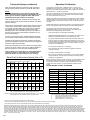
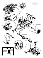
Owner's Manual
Model: ATVTS-60-12V-BL (5301305)
(60 Gallon, 12 Volt, Trailer Sprayer w/Deluxe Handgun & "Boomless" Boom Assembly)
Technical Specifications
- Corrosion-Resistant Polyethylene Tank
- 12 Volt, 11 Amp, 45psi, 3.8gpm Pump
- Pressure Gauge - Adjustable Pressure
- Suction Line Filter
- Deluxe Pistol Grip Handgun (w/25 Ft. of Hose)
- 3-Nozzle "Boomless" Boom Assembly
- 30 Foot Spray Coverage
- Pneumatic Tires, 18 x 950 - 8
- 10 m.p.h. MAXIMUM
Assembly
Most of the sprayer has been assembled at the factory.
Attach the axle to the trailer frame with (4) bolts & nuts as shown
in the exploded view drawing. Slide a wheel onto the hub of the
axle and use the wheel nuts to hold the wheel in place.
The (2) boom mounting brackets are to be mounted on the
trailer frame. Use 4 flange bolts and whiz nuts to secure them in
place. (see exploded view)
Center the boom tube on the boom mounts and secure in place
with the (2) round u-bolts and whiz nuts provided.
General Information
Thank you for purchasing this product. The purpose of this
manual is to assist you in operating and maintaining your trailer
sprayer. Please read it carefully, as it furnishes information
which will help you achieve years of trouble-free operation.
Warranty/Parts/Service
For home usage, products are warranted for one year from date
of purchase against manufacturer or workmanship defects.
Commercial users have a 90 day warranty.
Your authorized dealer is the best source of replacement parts
and service. To obtain prompt, efficient service, always
remember to give the following information...
Make sure the u-bolts are positioned within the grooves of the
grommets on the boom tube.
NOTE: The purpose of these grommets is to prevent metal-tometal contact between the u-bolts, boom tube, and boom
mounting brackets. The grommets will 'compress' as you tighten
the whiz locknuts onto the u-bolts. Tighten just so that the boom
tube will NOT rotate within the grommets. Alternate the
tightening of the locknuts to provide even pressure on the
grommet.
** DO NOT OVER-TIGHTEN the whiz locknuts, as this may
cause the boom tube to flatten slightly!
Attach the boom feeder hose to the boom after routing it through
the underside of the frame as needed. Secure in place with a
hose clamp provided.
- Correct Part Description and/or part number.
- Model number/Serial number of your sprayer.
Part descriptions and part numbers can be obtained from the
illustrated parts list section(s) of this manual.
Whenever you need parts or repair service, contact your
distributor/dealer first. For warranty work, always take your
original sales slip, or other evidence of purchase date, to your
distributor/dealer.
www.fimcoindustries.com
1000 FIMCO Lane, P.O. Box 1700, North Sioux City, SD 57049
Toll Free Phone: 800-831-0027 : Toll Free Fax: 800-494-0440
Form No. 834 [5004612 (02/14)] Printed in the U.S.A.
Testing the Sprayer (continued)
Operation & Calibration
Open the tank lid and be sure the tank is clean and free of
foreign material. Fill the tank about 1/2 full with plain water.
NOTE:
It is VERY important for you to test your sprayer with
plain water before actual spraying is attempted. This will
enable you to check the sprayer for leaks, without the
possibility of losing any expensive chemicals.
Open the suction line valve. (located next to the pump) The
valve is located at this point to enable the strainer to be taken
apart for cleaning.
There are (2) valves located on the manifold. One is a shut off
for the boom, and the other is used to bypass solution back
into the tank, thus decreasing the overall system's pressure.
The bypass valve is the "pressure control" for the entire
plumbing system. The more that valve is open the lower the
pressure. Fully closed provides maximum pressure to your
boom and/or handgun.
You may now start the sprayer. Solution will begin spraying
from the boom nozzles when the valve to that line is opened.
Initially have the pressure line open to the tips so that the air
which may be trapped in the line will be forced (or purged) out.
Check the entire system for leaks.
During the testing period, be sure to observe the spray pattern
given by the spray nozzles. If there is any pattern distortion, it
will be necessary to remove and clean the affected tips.
Caution: Never use a metal object or other sharp item for
cleaning a nozzle tip. It is better to use a nozzle brush
(NOT wire brush) or compressed air for tip cleaning.
Rate Chart for Boomless Nozzle (Set of 3)
Gallons per Acre Based on Water - 17 1/2" Spacing
Note: The same figures are used for 1, 2, or 3 nozzles.
Pressure Capacity
G.P.M. 1 MPH 2 MPH 3 MPH 4 MPH 5 MPH 6 MPH 8 MPH
P.S.I.
(3 Nozzles)
20
30
40
1.68
2.05
2.40
28.0
34.4
39.6
14.0
17.2
19.8
9.4
11.4
13.2
7.0
8.6
9.9
5.6
6.9
7.9
4.7
5.7
6.6
3.5
4.3
5.0
Your sprayer is equipped with (1) ON/OFF switch. It is on the wire
assembly that you hook up to your battery. The "-" is the "ON" position
and the "o" is the "OFF" position for the switches. Make sure the switch is
depressed in the "-" position for operation.
The pump is equipped with an electronic pressure switch that is factory
pre-set for it to shut off at 45 p.s.i.. This switch assembly is the 'square
box' on the head portion of the pump.
Always fill the tank with a desired amount of water first, and then add the
chemical slowly, mixing as you pour the chemical into the tank. You may
use the handgun to spray into the solution in order to mix the chemical
and water.
Initially begin spraying by opening the handgun. This will enable the air in
the line to be purged through the handgun tip, while building pressure.
The pumping system draws solution from the tank, through the
strainer/filter, and to the pump. The pump forces the solution under
pressure to the handgun and/or boom nozzles.
•
Open the handgun by squeezing the handle lever.
•
Rotating the adjustable nozzle tip on the handgun will change the tip
pattern from a straight stream to a cone pattern (finer mist).
•
The pump's electronic pressure switch shuts the motor off when all
lines are closed. The system will remain pressurized, and the pump
motor will restart automatically when either the handgun, or boom line
is opened. If the bypass line valve is in the open position, the pump
will not shut off automatically.
•
The (3) nozzles are fixed at 17 1/2" spacing.
•
All (3) nozzles spraying at the same time will allow a maximum
coverage of 30 feet.
•
The center nozzle will spray an 80" swath.
•
Each of the (3) nozzles has a shutoff valve, so you can shut off each
nozzle individually. This may help in achieving the actual coverage
needed for your application.
When it becomes necessary to clean the screen, you will need to shut off
the ON/OFF valve next to the pump, on the inlet side. Remove the
screen. Rinse and tap out the dirty screen and put back in it's original
position when clean. Do this on a regular basis to maintain a clean
screen.
DO NOT EXCEED 10 M.P.H. AT ANYTIME
Speed Chart
Time Required in seconds to travel a distance of:
Gallons per 1000 Sq. Ft. Based on Water - 17 1/2" Spacing
Pressure Capacity
P.S.I.
G.P.M. 1 MPH 2 MPH 3 MPH 4 MPH 5 MPH 6 MPH 8 MPH
(3 Nozzles)
20
30
40
1.68
2.05
2.40
0.64
0.78
0.90
0.32
0.39
0.45
0.21
0.26
0.30
0.16
0.20
0.23
0.13
0.16
0.18
0.11
0.13
0.15
0.08
0.10
0.12
Gallons per 100 Sq. Ft. Based on Water - 17 1/2" Spacing
Pressure Capacity
P.S.I.
G.P.M. 1 MPH 2 MPH 3 MPH 4 MPH 5 MPH 6 MPH 8 MPH
(3 Nozzles)
20
30
40
1.68
2.05
2.40
0.064
0.078
0.090
0.032
0.039
0.045
0.021
0.026
0.030
0.016
0.020
0.023
0.013
0.016
0.018
0.011
0.013
0.015
0.008
0.010
0.012
MPH = Miles Per Hour / FPM = Feet Per Minute
PSI = Pounds Per Square Inch / GPM = Gallons Per Minute
** The rate of spray as shown in the chart will remain the same with 1, 2, or 3 Nozzles. **
The only difference will be with the width of the spray swath.
Speed in M.P.H.
(Miles per Hour)
100 Ft.
200 Ft.
300 Ft.
1.0
68 sec.
136 sec.
205 sec.
2.0
34
68
102
3.0
23
45
68
4.0
17
34
51
5.0
14
27
41
6.0
11
23
34
7.0
9.7
19
29
8.0
8.5
17
26
9.0
7.6
15
23
10.0
6.8
14
20
Four things must be considered before spraying with the boom:
1.
How much chemical must be mixed in the tank?
2.
Rate of spray? (Gallons per Acre to be sprayed)
3.
What Pressure (p.s.i.) will be used?
4.
Speed Traveled (m.p.h.) while spraying?
- Refer to your chemical's label to determine the chemical mixture.
- See the tip chart to determine the pressure to be used. The chart will also show the speed used when spraying.
- If the towing vehicle does not have a speedometer, speed can be determined as per the directions.
Determining the proper speed of the pulling vehicle can be done by marking off 100, 200, & 300 feet. The speed chart indicates the number of seconds it takes to travel the
distances. Set the throttle and with a running start, travel the distances. Adjust the throttle until you travel the distances in the number of seconds indicated by the speed chart.
Once you have reached the throttle setting needed, mark the throttle location so you can stop and go again, returning to the same speed. Add water and proper amount of
chemical to the tank and drive to the starting place for spraying. Once you know how much you are going to spray, then determine (from the tip chart) the spraying pressure (PSI),
and the spraying speed (MPH). The pressure can be set by running the sprayer with the boom nozzles 'on', and then adjusting the relief valve until the gauge reads the desired
pressure. Notice that the pressure will go up when the boom line is shut off. This is normal, and the pressure will return as before when you open the boom line. When selecting
pressure from the tip chart, it is a good idea to try for the 20 or 30 p.s.i. range as this allows an excellent nozzle pattern. Spraying at 10 p.s.i. begins to break up the pattern, and at
40 p.s.i. you may notice some drift.
Page 2
Pump Model: 5277982
2
1
8
10
Item
Part
No
Number Qty Description
1
5075019 1 Pkg. (4) Grommets
2
5157206 1 15 Amp 'Mini Blade' Fuse
3
5168821 1 Upper Housing w/Pressure Switch
4 20408-000 1 Pkg. (2) Clips (Port Fitting)
5
5157203 1 Pressure Switch Assembly
6
5168824 1 Check Valve w/O-Ring
7
5168826 1 Diaphragm Kit w/Pistons & (4) Screws
8
5168828 1 Cam/Bearing Kit, w/Set Screw
9
5168832 1 Port Kit Fitting, 1/2" MNPT
5168833 1 Port Kit Fitting, 1/2" Hose Barb
10
7
6
4
5
9
3
Troubleshooting the Pump:
Pulsating flow (surging):
Motor does not run:
°
°
°
°
°
Check for loose wiring connection(s).
Make sure the 'ON/OFF' switch in the
lead wire assembly is in the 'ON' position.
"I" is the 'ON' position and 'O' is the 'OFF' position.
Check for defective pressure switch. Make sure
you are connected to a good 12 volt power source.
Make sure any on/off switches are in the 'on' position.
Remove the cap to the pressure switch. Pull both
red wires off of their terminals, and touch the two
ends together. If your pump runs when you do this,
your pressure switch will need to be replaced.
Check the fuse.
Check for low voltage at the power supply.
°
°
°
°
°
°
Check for defective pressure switch.
Check for leaks in the discharge line.
Check for restriction in the discharge line.
Check for debris in nozzle orifice.
Discharge hose may be too long.
Check for clogged strainer.
Motor continues to run after discharge is shut off:
°
°
°
°
°
°
Check for empty product supply.
Check for open bypass valve. (if equipped)
Check for low voltage.
Check for leak in discharge line.
Check for defective or dirty check valve.
Check for defective pressure switch.
Pump Specifications
Pump does not prime:
°
°
°
°
°
°
Available Replacement Parts
Check for air leaks in supply line.
Check for debris in the check valve assembly.
Check for defective check valve.
Check for clogged strainer/filter.
Check for cracks in the pump housing.
Check for empty product supply.
Flow Rate:
3.8 GPM @ Open Flow
Current:
7.4 Amps @ 40 PSI
Check Valve:
Viton
Port Type:
Plug-In Port
Motor Voltage:
12 Volts DC
Wetted Parts Housing: Polypropylene
Fuse
2.250
Diaphragm:
Santoprene
Liquid Temperature:
130° F max.
GPM = Gallons Per Minute
PSI = Pounds per Square Inch
DC = Direct Current
Outlet
12V Connection
Pump Model Number
3.188
Inlet
Pump Serial Number
Page 3
End Nozzle Assembly Procedure
for Boomless "Wet" Boom
Assembled
End Nozzle
Assembled
End Nozzle
(Sectioned Body)
(Face1) to butt end of
boom tube up against.
15
Your boom will come with the end nozzle
assemblies (2) NOT affixed to your boom tube.
Follow the instructions below to attach these
properly to the boom tube, as shown.
"Long" portion
16
1.
Start by sliding Item 17, 16, & 15 onto your boom tube as shown,
leaving about 1/2" to 3/4" between the end of the boom tube and Item 15.
Make sure the "Long" portion of Item 16 is facing the nozzle end.
17
2. Slide the (complete) end nozzle assembly onto the stainless steel
boom tube, with a somewhat "twisting" motion so that the end face of the
boom tube "butts" up against "Face1" as noted.
3. Now push the "compression olive" (Item 16) against o-ring (Item 15) and
slide (both) into the nozzle body opening firmly.
4. Firmly tighten flynut (Item 17) onto threads of nozzle body.
5. Repeat for other side.
"On/Off" Valve Positions
End Nozzle Information
(#5275122)
Valve "Open"
Valve "Closed"
This nozzle mounting stem
has a ratcheting motion.
** Each "click" of the ratcheting motion is approx. 15° **
15°
On/Off Valve Knob
For proper/optimal spray coverage, the
nozzle must be at a 15° angle
The 15° angle shown will prevent the outer
nozzles from overlapping with the center nozzle.
Page 4
Serivce Position
Eliminate line pressure, then pull
out to check diaphragm condition.
Note: The check valve & diaphragm can fall out during transport,
if the knob is not turned to the "ON" or "OFF" position.
31
20
21
27
Exploded View:
ATVTS-60-12V-BL
(5301305)
22
27
15
15
Handgun Bracket
14
19
11
Intake/Pump
34
12
18
14
6
8
Boom Attachment
3
5
Axle Attachment
16
19
9
23
11
14
Manifold
2
2
36.2.4
36.2.6
36.2.3
36.2.2
10
19
37
28
36.2.5
36.3
(*)
Hub Assembly
18
37
7
2
33.7
4
25
36.2.1
30
1
36.1
32
Intake/Pump
29
13
34
12
18
28
33.6
Hub Assembly
33.7
33.2
3
33.4
7
33.1
33.8
23
37
33.4
33.5
17
33.3
33
26
37
2
23
23
35.4
24
Boom Attachment
35.3
Manifold
2
25
35.8
2
5116255
(*) Strainer
#5116417
5072356
9
35.1
Axle Attachment
35.5
5116177
5058072
19
35.7
35.5
35.2
35.9
35.6
35.8
35.7
35.5
35.6
35.7
Page 5
Parts List: ATVTS-60-12V-BL (5301305)
Item No Part Number Qty Description
1
5006186
4 #10-24 Hex Whiz (Flange) Locknut
2
5006259
12 3/8"-16 Hex Whiz (Flange) Locknut
3
5006307
4 5/16"-18 Hex Whiz (Flange) Locknut
4
5006337
2 1/2-13nc Hex Flanged Whiz Nut Gr. 5
5
5010202
1 Poly Elbow, 1/2" MNPT x 3/8" HB
6
5010203
1 Poly Elbow, 1/2" MNPT x 1/2" HB
7
5020152
1 Hose, 1/2"-1 Brd. x 6 Ft. (72")
8
5020228
1 Hose, 1/2"-1 Brd. x 36"
9
5020527
1 Hose, 3/8"-1 Brd. x 25 Ft.
10
5020538
1 Hose, 3/8"-1 Brd. x 43"
11
5034101
4 H.H.C.S., 3/8"-16 x 1 3/4"
12
5034220
2 Round U-Bolt, 5/16"-18 x 1 5/16" x 1 3/4"
13
5034700
2 H.H.C.S. Flanged 1/2"-13nc x 3 1/2" Long
14
5038698
4 Plastic Tank Hold-Down Leg Clip
15
5038775
1 Handgun Bracket
16
5038833
1 Boom Mount R.H.
17
5038834
1 Boom Mount L.H.
18
5051114
4 Hose Clamp (3/8"-1/2")
19
5051144
4 Hose Clamp, 3/8"
20
5058188
1 Tank Lid w/Lanyard
21
5075014
2 Rubber Grommet (Black)
22
5117234
2 #10-24 x 1/2" Phillips Truss Head Machine Screw
23
5117307
8 3/8"-16 x 1" Whiz (Flange) Lockscrew
24
5117314
1 #10-24 x 3" Truss Head Machine Screw
25
5127192
1 Manifold Spacer (3.8gpm)
26
5167007
1 Pressure Gauge, 0-100 p.s.i.
27
5169249
1 60 Gallon Elliptical Tank (White)
28
5272464
2 Wheel, 18 x 9.5 x 8 - 4-Bolt
29
5273204
1 Hitch Clevis Weldment
30
5273212
1 5 Ft. Extension Wire
31
5273959
1 Deluxe Pistol-Grip Handgun w/X-26 Tip
32
5274443
1 Lead Wire Assembly (w/Switch), 96"
33
5274955
1 Axle & Hub Assembly
33.1
5006301
8 1/2"-20 Hex Cone Wheel Nut
33.2
5072471
2 Grease Seal
33.3
5046327
2 Grease Cap
33.4
5031139
4 Cone Bearing
33.5
5006300
2 Castle Nut, 1"
33.6
5101081
2 Cotter Pin, 5/32" x 2-1/4"
33.7
5274954
1 Axle Weldment (ATVTS-60)
33.8
5085018
2 Hub Assembly (4-Stud)
34
5275260
1 "Wet Boom" Assembly
35
5277179
1 Manifold Assembly
35.1
5143405
1 Manifold w/Mounting Tab
35.2
5010430
1 Port Kit Elbow, 1/2" FNPT
35.3
5010236
1 Poly Elbow, 1/2" FNPT x 1/2" FNPT
35.4
5041073
1 Poly Reducing Bushing, 1/2" MNPT x 1/4" FNPT
35.5
5016066
3 Garden Hose Washer
35.6
5149034
2 Poly Swivel, 3/8" Hose Barb
35.7
5006209
3 Poly Knurled Swivel Nut, 3/4" FGHT
35.8
5143188
2 Nylon Shut-Off Valve (3/4" GHT)
35.9
5149035
1 Poly Swivel, 1/2" Hose Barb
36
5278066
1 Pump/Strainer Assembly
36.1
5277982
1 High Flo Gold Series 3.8 GPM Pump
36.2
5277174
1 Strainer/Valve Assembly
36.2.1
5010430
1 Port Kit Elbow, 1/2" FNPT
36.2.2
5116417
1 Nylon 'TEE' Line Strainer (1/2" MNPT, 50 Mesh)
36.2.3
5005190
1 Poly Adapter Coupler, 3/4" FGHT x 1/2" FNPT
36.2.4
5143188
1 Nylon Shut-Off Valve (3/4" GHT)
36.2.5
5067121
1 Poly Hose Fitting, 3/4" MGHT 1/2" HB
36.2.6
5016066
1 Garden Hose Washer
36.3
5117168
3 #10-24 x 1" Phillips Truss Head Machine Screw
37
5278078
1 Frame Weldment (ATVTS-60) (Red)
Maintenance During/After Spraying
Periodically close the suction line valve. Check the line strainer and
clean the screen. Always flush the entire plumbing system with water
or a neutralizing agent, such as FIMCO Tank Neutralizer and
Cleaner, after completing the spraying operation.
Proper care and maintenance will prolong the life of your sprayer.
After use, fill the sprayer tank part way with water. Start the sprayer,
and allow the clear water to be pumped through the plumbing system
and out through the spray nozzles.
Refill the tank about half full with plain water and use FIMCO Tank
Neutralizer and Cleaner, and repeat cleaning instructions above.
Flush the entire sprayer with the neutralizing/cleaning agent, then
flush out one more time with plain water. Follow the chemical
manufacturer's disposal instructions of all wash or rinsing water.
For the boom, (if applicable) remove the tips and screens from the
nozzle assemblies. Wash these items out thoroughly. Blow the orifice
clean and dry. If the orifice remains clogged, clean it with a fine bristle
(NOT WIRE) brush, or with a toothpick. Do not damage the orifice.
Water rinse and dry the tips before storing.
WARNING: Some chemicals will damage the pump valves if allowed
to soak untreated for a length of time! ALWAYS flush the pump as
instructed after each use.
Winter Storage
Drain all water out of your sprayer, paying special attention to the
pump, handgun, and valve(s). These items are especially prone to
damage from chemicals and freezing weather.
The sprayer should be winterized before storage by pumping a
solution of RV antifreeze through the entire plumbing system. This
antifreeze solution should remain in the plumbing system during the
winter months. When spring time comes and you are preparing your
sprayer for the spray season, rinse the entire plumbing system out,
clearing the lines of the antifreeze solution. Proper care and
maintenance will prolong the life of your sprayer.
Information About The Sprayer
In this pumping system, solution is drawn from the tank, and forced
to a planned source, such as boom nozzles, or handgun. The
pressure is controlled by opening/closing the valve which
recirculates solution back into the tank..
1.8.1
#5275260 "Wet" Boom Assembly
1.8.2
1.1
1.3
1.4
2.2.1
1.5
2.3
2.2.2
2.2.8
2.3
1.2
1
2.1
1.7
2.2.7
2.2.3
1.6
2.2.5
2.2.6.1
2.2.4
Page 6
Item
Part Number
No
1
5275122
1.1
5002499
1.2
5072518
5072517
1.3
1.4
5010427
1.5
5006348
1.6
5132073
1.7
5274861
1.8.1
5088024
1.8.2
5063255
2
5275712
2.1
5100316
Qty Description
2
1
1
1
1
1
1
1
1
1
1
1
End Nozzle Assembly (Wet Boom)
Boomless Nozzle Body w/Core (Outer)
Stem O-Ring
Compression O-Ring
Compression Olive
Flynut
Nozzle Holder Stem
XT Spray Nozzle, Cap, & O-Ring
Yellow ON/OFF Valve Knob
Diaphragm
Wet Boom Sub-Assembly
Boom Tube
2.2.6.2
Item
Part Number
No
2.2
5275123
2.2.1
5051137
2.2.2
5072509
2.2.3
5002500
2.2.4
5274862
2.2.5
5018329
2.2.6.1
5088024
2.2.6.2
5063255
2.2.7
5117310
2.2.8
5006347
2.3
5075016
Qty Description
1
1
2
1
1
1
1
1
2
2
2
Center Nozzle Assembly (Wet Boom)
Hose Barb Saddle
O-Ring
Center Nozzle Body w/Core (Wet Boom)
Center Boomless Nozzle Cap w/Gasket
Red Spray Tip
Yellow ON/OFF Valve Knob
Diaphragm
SS Screw, 6mm x 16mm (5/8")
SS Nut, 6mm
Rubber Grommet