1
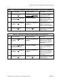
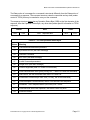
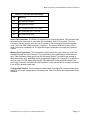
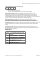
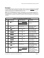
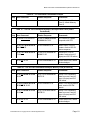
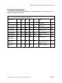
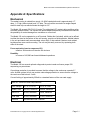
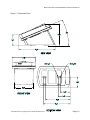
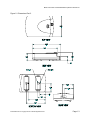
MODEL 152 Smart Card Reader OPERATION INSTRUCTIONS 8182760, REVISION G Co p yr i gh t© 19 9 9, AX IO HM T r a ns ac t io n S o l ut io ns , Inc . A l l R i gh ts Res er v e d Model 152 Smart Card Reader/Writer Operation Instructions FCC This equipment has been tested and found to comply with the limits for a class B digital device, pursuant to part 15 of the FCC rules. These limits are designed to provide reasonable protection against harmful interference in a residential installation. This equipment generates, uses and can radiate radio frequency energy and, if not installed and used in accordance with the instructions, may cause harmful interference to radio communications. However, there is no guarantee that interference will not occur in a particular installation. If this equipment does cause harmful interference to radio or television reception, which can be determined by turning the equipment off and on, the user is encouraged to try to correct the interference by one or more of the following measures: Reorient or relocate the receiving antenna. Increase the separation between the equipment and receiver. Connect the equipment into an outlet on a circuit different from that to which the receiver is connected. Consult the dealer or an experienced radio/TV technician for help. This equipment has been certified to comply with the limits for a class B computing device, pursuant to FCC Rules see Appendix H: Declaration of Conformity. In order to maintain compliance with FCC regulations, shielded cables must be used with this equipment. Operation with non-approved equipment or unshielded cables is likely to result in interference to radio and TV reception. The user is cautioned that changes and modifications made to the equipment without the approval of the manufacturer could void the user’s authority to operate this equipment. Statement of Electromagnetic Compliance This product has passed all electromagnetic interference and susceptibility testing required by the European Community and thus bears the "CE" mark This Class B Digital Apparatus meets all requirements of the Canadian Interference Causing Equipment Regulations. Notice The information contained in this manual is subject to change without prior notification. Axiohm American Magnetics Division shall not be held liable for technical and editorial omissions or errors made herein; not for incidental, or consequential damages resulting from the furnishing, performance or use of this material. This document contains proprietary information protected by copyright. All rights are reserved. No part of this document may be photocopied without prior, written permission of Axiohm. Trademarks All terms used in this document that are known to be trademarks or service marks have been capitalized where appropriate. AMC cannot attest to the accuracy of this information. Use of a term should not be regarded as affecting the validity of any trademark or service mark. 8182760 Revision G Copyright Axiohm 1998 All Rights Reserved Page 2 Model 152 Smart Card Reader/Writer Operation Instructions Table of Contents FCC .........................................................................................................................................i Statement of Electromagnetic Compliance...................................................................................i Notice .........................................................................................................................................i Trademarks ..................................................................................................................................i Table of Contents........................................................................................................................ii Tables and Figures.................................................................................................................... .iii Chapter 1: Introduction ........................................................................................................... 1.1 Appearance ................................................................................................................. 1.1 Features ...................................................................................................................... 1.1 Accessories ................................................................................................................. 1.1 Other Documents of Interest ........................................................................................ 1.2 Chapter 2: Installation ............................................................................................................ 2.1 Hardware ..................................................................................................................... 2.1 Configuration / Demo Software .................................................................................... 2.2 Technical Support........................................................................................................ 2.2 Chapter 3: Basic Operation ..................................................................................................... 3.1 Transmission Parameters ............................................................................................ 3.1 Host Protocols ............................................................................................................. 3.1 Power Cycle/Reset........................................................................................... 3.1 Chapter 4: USI2 Protocol........................................................................................................ 4.1 Transport layer ............................................................................................................ 4.1 Basic Frame Structure ................................................................................................. 4.1 Commands .................................................................................................................. 4.2 Table 3 - USI2 Reader Commands .................................................................. 4.2 USI2 Reader Command Details................................................................................... 4.2 Table 5 - USI2 Card Commands ...................................................................... 4.4 Responses from Card Reader to the Host ................................................................... 4.5 Status Bytes ................................................................................................................ 4.5 Examples..................................................................................................................... 4.7 Chapter 5: TLP-224 Protocol ................................................................................................... 5.1 Transport layer ............................................................................................................ 5.1 Response Operation Status Byte................................................................................. 5.2 Commands .................................................................................................................. 5.3 Table 14 - TLP-224 Reader Commands........................................................... 5.3 Table 16 - TLP-224 Card Commands............................................................... 5.5 Responses................................................................................................................... 5.6 Examples..................................................................................................................... 5.7 8182760 Revision G Copyright Axiohm 1998 All Rights Reserved Page iii Model 152 Smart Card Reader/Writer Operation Instructions Chapter 6: TLP-224Turbo Protocol ......................................................................................... 6.1 Chapter 7: ISO TPDU Command/Response Structure ........................................................... 7.1 TPDU Command Structure .......................................................................................... 7.1 TPDU Response Structure .......................................................................................... 7.1 Chapter 8: Memory Card Support........................................................................................... 8.1 Commands Supported ................................................................................................. 8.2 Appendix A: Specifications ................................................................................................... A.1 Mechanical .................................................................................................................. A.1 Electrical ...................................................................................................................... A.1 Environmental.............................................................................................................. A.4 Appendix B: FCC Declaration of Conformity........................................................................... B.1 Glossary..................................................................................................................................C.1 Index D.1 8182760 Revision G Copyright Axiohm 1998 All Rights Reserved Page iv Model 152 Smart Card Reader/Writer Operation Instructions Tables and Figures Table 1 - Power Jack............................................................................................................... 2.1 Table 2 - DB-9 Connector........................................................................................................ 2.1 Table 3 - USI2 Reader Commands ......................................................................................... 4.2 Table 4 - Memory Card Types ................................................................................................. 4.3 Table 5 - USI2 Card Commands ............................................................................................. 4.4 Table 6 - Responses from Card Reader to the Host ................................................................ 4.5 Table 7 - First Status Byte .................................................................................................... 4.5 Table 8 - Second Status Byte.................................................................................................. 4.5 Table 9 - Response to Configuration Request ......................................................................... 4.6 Table 10 - USI2 Reader Commands Example......................................................................... 4.7 Table 11 - USI2 Card Commands Example, Microprocessor Card (Solaic PocketBook .......... 4.8 Table 12 - USI2 Card Commands Example, Memory Card (AT24C01A)................................. 4.8 Table 13 - TLP-224 Operation Status Bytes ............................................................................ 5.2 Table 14 - TLP-224 Reader Commands.................................................................................. 5.3 Table 15 - TLP-224 LED Control Byte ..................................................................................... 5.4 Table 16 - TLP-224 Card Commands...................................................................................... 5.5 Table 17 - TLP-224 Reader Status Byte Format...................................................................... 5.6 Table 18 - TLP-224 Reader Commands Example ................................................................... 5.7 Table 19 - TLP-224 Card Commands Example, Microprocessor Card (Solaic PocketBook).... 5.9 Table 20 - TLP-224 Card Commands Example, Memory Card (AT24C01A) ........................... 5.9 Table 21 - Memory Card Commands Supported ..................................................................... 8.2 Table 22 - Electrical Power Requirements............................................................................... A.1 Figure 1 - Dimensions Part 1................................................................................................... A.2 Figure 2 - Dimensions Part 2................................................................................................... A.3 Table 23 - Environmental Requirements ................................................................................. A.4 8182760 Revision G Copyright Axiohm 1998 All Rights Reserved Page v Model 152 Smart Card Reader/Writer Operation Instructions Chapter 1: Introduction This booklet describes the requirements, operation, and usage of the Model 152 Smart Card Reader/Writer (the “reader”). This booklet should be read and understood prior to initial operation of the reader. Appearance The Model 152 is a manually operated insert reader for Smart Cards. The reader is contained in an attractive plastic housing which allows easy insertion and withdrawal of smart cards. It may be used with or without its base. The housing is suitable for desk top, cabinet top, and cabinet side mounting. Features • • • • • • • • ISO 7816 compliant. Supports Microprocessor Cards requiring a variety of f/d ratios (speeds). Supports a minimum speed of 1920 bps and a top speed of 38400 bps, with various speeds in between. Reads and writes Microprocessor Cards using either T=0 or T=1 protocol.* RS232 compatible. Reads and writes a variety of Memory Cards. Capable of accessing up to 8 Secure Application Module (SAM) cards in addition to the card in the User Connector. Can use one of three communication protocols to talk with the host: AMC USI2, TLP-224, or TLP-224Turbo. Gives the host full control over the LEDs. Allows the host to interrogate the device about current status and configuration information. Accessories • • • • • • A power supply AC/DC adaptor is available which complies with your local power requirements. Smart Card prototyping and training software for learning and demonstrating capabilities of Smart Card technology using the Model 152. Local Connector (LSAM) for a Secure Application Module (SAM), in the GSM size. This accessory must be specified when ordering the reader, it is not field upgradable. CTS for flow control. This option allows the host to block transmission from the reader. This option must be specified when ordering the reader, it is not field upgradable. External SAM boxes allowing access of up to seven additional SAM cards. Axiohm - American Magnetics Division is committed to working with users to meet their special requirements. * Supports T=1 cards with using LRCs in the EDC field. 8182760 Revision G Copyright Axiohm 1998 All Rights Reserved Page 1.1 Model 152 Smart Card Reader/Writer Operation Instructions Other Documents of Interest ISO 7816-3 Identification Cards - Integrated circuit(s) cards with contacts Part 2: Dimension and location of the contacts (1988) Part 3: Electronic signals and transmission protocols (1989) Amendment 1: Protocol type T=1, asynchronous half duplex block transmission protocol Amendment 2: Revision of protocol type selection Part 4: Interindustry commands for interchange 8182760 Revision G Copyright Axiohm 1998 All Rights Reserved Page 1.2 Model 152 Smart Card Reader/Writer Operation Instructions Chapter 2: Installation Hardware 1. Attach a suitable (See electrical specifications) power supply to the DB-9 connector and to a wall socket. 2. A 6 foot (1.8 meter) cable terminated with a female DB-9 connector is permanently attached to the reader. The DB-9 housing has a power jack with a 2.1 mm diameter center pin as positive polarity. See electrical specifications for power requirements. 3. Attach the DB-9 connector to a suitable RS232 connector on your host system. See tables 1 and 2 below for the cable pinouts. 4. Mount the reader in a suitable location for your application. You may use the included rubber feet, velcro, or slotted screw mounts as desired. The base may be separated from the body of the reader by squeezing the sides of the base and pulling. Table 1 - Power Jack CenterPin +Vin IN Blade Circuit Ground ---- Table 2 - DB-9 Connector 1 Not Used 2 TXD OUT 3 RXD IN 4 Not Used --- 5 Circuit Gnd --- 6 Not Used --- 7 CTS IN 8 Not Used --- 9 Not Used --- Chassis Gnd --- Case --- 8182760 Revision G Copyright Axiohm 1998 All Rights Reserved Page 1.1 Model 152 Smart Card Reader/Writer Operation Instructions Configuration / Demo Software The Model 152 ships from the factory with certain default conditions. These defaults can be changed by running the configuration program (available from American Magnetics Division of Axiohm) which may be used to change certain operational conditions. Using the demo/configuration program is easy, simply launch it from a Microsoft Windows® environment and follow the instructions. You will need to know to which serial communication port the reader is attached (e.g COM1). The configuration program will lead you through a series of steps to complete your configuration successfully. Once configured, the reader retains the new configuration in its permanent memory. The configuration program also contains a demonstration mode. From the main screen simply click on a command to execute and click on the execute button. To configure the reader click on the configure button. When you have finished selecting the configuration options, simply click the done tab and click on the OK - write to the EEPROM button to update the EEPROM and return to the main screen. The demo allows you to explore all the functions of the Model 152. Technical Support For technical support, call Axiohm - American Magnetics Division at one of the phone numbers found on the back cover of this manual. 8182760 Revision G Copyright Axiohm 1998 All Rights Reserved Page 1.2 Model 152 Smart Card Reader/Writer Operation Instructions Chapter 3: Basic Operation Transmission Parameters Each character is transmitted using 8 data bits, no parity, and 1 stop bit. The factory default speed is 9600 bps. Other speeds may be chosen using the configuration program. The other speeds are: 38400, 19200, 4800, 2400, and 1200 bps. Host Protocols The Model 152 supports three communications protocols to talk with the host. They are: USI2, TLP-224, TLP-224Turbo USI2 is a proprietary protocol developed by Axiohm - American Magnetics which has features allowing it to be used for multi-dropping and for large (up to 64K bytes) messages. Though the Model 152 does not support multi-dropping at this time, a future variation of the device may. TLP-224 is a protocol used by several manufacturers of Smart Card devices. There are a core set of functions defined, which, if used exclusively, provide for plug compatibility between different manufacturer’s readers. The AMC implementation has all of the core functions plus a few more which you may use at your discretion. TLP-224Turbo is an AMC originated variant of the TLP-224 protocol. The standard TLP-224 protocol requires each byte to be split into two ASCII readable bytes for transmission. This effectively doubles the communication time for each message. The TLP-224Turbo protocol corrects this problem by simply not splitting bytes. If you like TLP-224, but don’t like its speed, you may want to try TLP-224Turbo. Power Cycle/Reset Cycling the power to the Model 152 will cause the device to loose the contents of volatile memory, including the information on the current card and selected connector. When power is restored the device checks the validity of the EEPROM to make sure they are functioning correctly. The host needs to set all the parameters stored in volatile memory before resuming. 8182760 Revision G Copyright Axiohm 1998 All Rights Reserved Page 1.1 Model 152 Smart Card Reader/Writer Operation Instructions Chapter 4: USI2 Protocol Transport layer Each message sent to or from the reader must be formatted according to the protocol rules. A maximum of 100 milliseconds is allowed between successive bytes of a message; if more than 100 ms passes without a new byte, the message is considered spurious and is ignored. The receiver then starts to look for a new message. Basic Frame Structure Header SOH ADDR LENH LENL Data Trailer COMMAND or RESPONSE BCC Data Trailer COMMAND or RESPONSE EOT OR Header SOH ADDR LENH LENL BCC SOH is the value 01H and is used to signal the start of a message ADDR is the address of the intended recipient. The host is always address 00H. Each reader may be assigned a different address if desired. Readers will ignore messages sent to other addresses. The factory default address is 00H. This address feature is meant for future use in multi-drop configurations. LENH and LENL give the length of the Data portion of the message. Together they are considered as an integer with LENH as the high order portion and LENL as the low order portion. If the value of LENH and LENL are both zero, the length of the Data portion is determined by the presence of the EOT byte. COMMAND is the message being sent. This is either a command to the reader or a response from the reader. If LENH and LENL are not both equal to zero, any values may be sent in the COMMAND field. If LENH and LENL are both zero, any value except the EOT character may be sent as part of COMMAND. EOT is optional. It is present only in messages where LENH and LENL are both equal to zero. In these messages, EOT signals the end of the Data portion of the message. The value of EOT is 04H. BCC is the block check character. Its value is computed by exclusive oring the value of all preceding bytes in the message, back to and including the SOH byte. Commands 8182760 Revision G Copyright Axiohm 1998 All Rights Reserved Page 1.1 Model 152 Smart Card Reader/Writer Operation Instructions There are two types of commands which can be sent to the reader. The first type is used to manipulate the reader (LEDs, status, etc.). The second type is used to manage I/O with cards. Tables 3 & 5 show the commands of each type. Table 3 - USI2 Reader Commands ASCII HEX Name Use % 25 Retransmit Retransmits the last message again 9 39 Version Report Transmits Version String DEL 7F Warm Reset Simulates power cycle $ 24 Reader Status Request Transmits Reader Status Bytes (see Tables 7 & 8) L 4C Green LED ON Turns on Green LED l 6C Green LED OFF Turns off Green LED ( 28 Green LED FLASH Flashing Green LED (Firmware Beta 2.22 & later) M 4D Red LED ON Turns on Red LED m 6D Red LED OFF Turns off Red LED ) 29 Red LED FLASH Flashing Red LED (Firmware Beta 2.22 & later) C 43 Select Card Connector Selects the card connector to be used with the following card I/O commands T 54 Memory Card Type Select Selects the type of Memory Card for use with the following Memory Card Commands 8 38 Switch Report Read and report state of card seated switch (Firmware Beta 2.22 & later) # 23 Configuration Request Transmits Reader Configuration Bytes USI2 Reader Command Details Retransmit Command. Use this command when you detect a communication error in a message received from the reader. The reader will re-transmit the last response it transmitted before this request. The host may request re-transmits as many times as it likes. Version Report. Use this Command when you want to know the version of the Model 152 firmware currently loaded. The response is an ASCII string giving the firmware ID. Warm Reset. Use this command when you want the reader to simulate a power cycle. As on any power up, the Power Up Message will be sent by the reader. 8182760 Revision G Copyright Axiohm 1998 All Rights Reserved Page 1.2 Model 152 Smart Card Reader/Writer Operation Instructions Reader Status Request. Use this command to interrogate the reader about its operational status. Two bytes of status information will be returned. ICC Power and Card Seated bits refer to the currently selected card connector. Card Seated is only meaningful for the User Connector. See Tables 7 & 8 for an interpretation guide for these bytes. LED Commands. Use these commands to manipulate the LEDs on the reader (Firmware Beta 2.22 & later has flashing mode). Select Card Connector. The Model 152 supports up to 9 card connectors. This command tells the reader which connector is to be used with succeeding Card I/O Commands. The User Connector (the only one the user can see) is number 0, and is always selected after a power cycle. The Local Sam (GSM connector) is number 1. The remote SAM box contains up to 7 more connectors, numbered 2-8. The byte following the command byte codes the Connector number. Memory Card Type Select. This command is used to specify the type of Memory Card to be accessed through the User Connector. The byte following the command byte codes the card type. Table 4 shows the card types, type 0 is the factory default. The default type (always in effect after power up) is selectable via the configuration program. By using type 0, a read of the first four bytes (0-3) will always give the ISO 7816 defined ATR for synchronous cards if the card in the connector conforms to the ISO standard. A user may be able to use the information in the ATR to determine card type. Table 4 - Memory Card Types TYPE CARDS 00H Siemens SLE4406, SLE4436, SGS Thomson ST1305, Solaic E192B 01H Siemens SLE4418, SLE4428 02H Siemens SLE4404, GemPlus GPM416-5V, GPM896, Atmel AT88SC101, AT88SC102, Incard MS101, MS102, AMMI AM0101, AM0102 03H Siemens SLE4432, SLE4442 04H 3 Byte I2C Protocol, Atmel AT24C01a - AT24C16, SGC Thomson ST14C02C 05H 4 Byte I2C Protocol, Microchip 24LC65 06H Xicor X76F041* 07H Xicor X76F640* Configuration Request This command is used to obtain a configuration response which gives details of the current configuration in the reader. See Table 9 for format and interpretation of the response. Switch Report. This command will return a “p” (hex 70) if no card is inserted or “s” if a card is inserted. In automatic response mode the reader will send either “p” or “s” whenever the state of the switch changes (Firmware Beta 2.22 & later). 8182760 Revision G Copyright Axiohm 1998 All Rights Reserved Page 1.3 Model 152 Smart Card Reader/Writer Operation Instructions Table 5 - USI2 Card Commands ASCII HEX Name Use N 4E ICC Power ON Power on Microprocessor Card, return ATR n 6E ICC Power OFF Power off card, Microprocessor or Memory A 41 *Output to Microprocessor Card T=0 Sends request (and maybe data) to a Microprocessor Card a 61 *Input from Microprocessor Card T=0 Sends request to a Microprocessor Card, waits for response data F 46 *I/O microprocessor Card T=1 Sends request to a Microprocessor Card, waits for response data and/or status bytes B 42 *I/O to Memory Card Performs an operation on a Memory Card. * these commands are followed by a TPDU as explained in Chapter 7.The Command and TPDU may be sent in separate messages, or together. If they are sent in separate messages, the reader will transmit an ACK response after receiving the Command and wait for the TPDU message. Upon receipt of the TPDU, the TPDU will be processed (with resulting card I/O), and the response returned to the user. ICC Power ON. This command is used to power up a Microprocessor Card in the currently selected connector. It will follow the ISO power up sequence and return the ATR as the response. Memory Cards do not have an explicit power up command, rather the first I/O operation directed to the card causes a power up, which is performed according to the specifications for the current Memory Card type. ICC Power OFF. This command is used to power down the card in the currently selected connector. It will work for any type of card. Output to Microprocessor Card. This command is used to pass a TPDU to a Microprocessor Card using T=0, where only an ISO status reply is expected from the card. Because different Microprocessor Cards use different TPDU commands, the host must specify (via command selection) whether any data is expected in reply. WARNING: If you use this command to send a TPDU which generates a data response, results are undefined. Input from Microprocessor Card. This command is used to pass a TPDU to a Microprocessor Card using T=0, where both data and an ISO status are expected in the response. If you pass a TPDU with data intended for the card, the data will not be sent by this command. I/O Microprocessor Card. This command is used to pass a TPDU to a Microprocessor Card using T=1, where both data and an ISO status may be expected in the response. I/O to Memory Card. This command is used to perform all operations with a Memory Card. This command will always include a TPDU. Valid TPDUs are defined in Chapter 8 Memory Card Support and Appendices 8182760 Revision G Copyright Axiohm 1998 All Rights Reserved Page 1.4 Model 152 Smart Card Reader/Writer Operation Instructions Table 6 - Responses from Card Reader to the Host ASCII HEX NAME MEANING ^ 5E Acknowledge Acknowledges correct completion of most recent command * 2A Error Command was received correctly, but could not be completed. ? 3F Communication Error Command was not received correctly. ! 21 Invalid Command Command was received correctly, but is not a recognized command : 3A Power On Report The reader has just completed a power cycle, either real or via the Warm Reset command ISO TPDU Response TPDU processing complete. See Chapter 7 for format. Unavailable Hardware not available to complete this request ~ 7E Status Bytes Table 7 - First Status Byte Bit Position ’0’ ’1’ 0 RFU, always 0 1 Card not seated 2 RFU, always 0 3 ICC Power OFF ICC Power ON 4 Auto slot switch OFF Auto slot switch ON 5,6,7 Card seated Unused, always 0 Table 8 - Second Status Byte Bit Position Meaning 0,1 00 - Green LED OFF 01 -Green LED ON 10 -Green LED FLASHING 2,3 00 - Red LED OFF 01 - Red LED ON 10 - Red LED FLASHING 4,5,6,7 Not used, Always’0’ 8182760 Revision G Copyright Axiohm 1998 All Rights Reserved Page 1.5 Model 152 Smart Card Reader/Writer Operation Instructions Table 9 - Response to Configuration Request (16 bytes) 0 Equip ment 0 1 RFU 2 3 4 5 6 7-15 Prot Speed Addr Actual Mem. Card Type Default Mem. Card Type RFU Table 9a - Equipment Byte 0 7 6 5 4 3 2 1 0 RFU RFU RFU RFU CTS RFU Local SAM User Card Equipment may be any of the following: 01H - User Connector only 03H - User Connector and Local SAM 09H - User Connector and CTS (Clear to Send) 0BH - User Connector, Local SAM and CTS Protocol is one of: 0=USI2, 1=TLP-224, 2=TLP-224Turbo Speed is one of: 0=1200, 1=2400, 2=4800, 3=9600, 4=19200, 5=38400 Address is the actual address byte used to access this device (meaningful only if communicating with USI2 protocol) Memory Card Types per Table 4 8182760 Revision G Copyright Axiohm 1998 All Rights Reserved Page 1.6 Model 152 Smart Card Reader/Writer Operation Instructions Examples In the following examples, the protocol envelope is shown in normal, unenhanced text; the device information (commands, device responses) is underlined; and TPDU requests and responses are in bold. All values are in hex. Table 10 - USI2 Reader Commands Example Step Host Command Reader Response Comments 1 01 00 00 01 39 39 01 00 00 15 39 36 31 30 33 30 2C 41 4D 43 20 4D 31 35 32 2C 56 31 2E 30 30 44 Version String request and response 2 01 00 00 01 25 25 01 00 00 15 39 36 31 30 33 30 2C 41 4D 43 20 4D 31 35 32 2C 56 31 2E 30 30 44 Retransmit request and given. 3 01 00 00 01 7F 7F 01 00 00 01 3A 3A Warm Reset and Power Up Response 4 01 00 00 01 24 24 01 00 00 02 02 00 01 Status Request, reply shows Card Seated 5 01 00 00 01 4C 4C 01 00 00 01 5E 5E Turn on Green LED, reader Acknowledges 6 01 00 00 01 4D 4D 01 00 00 01 5E 5E Turn on Red LED, reader Acknowledges 7 01 00 00 01 6C 6C 01 00 00 01 5E 5E Turn off Green LED, reader Acknowledges 8 01 00 00 01 6D 6D 01 00 00 01 5E 5E Turn off Red LED, reader Acknowledges 9 01 00 00 02 43 00 40 01 00 00 01 5E 5E Select Connector 0, reader Acknowledges 10 01 00 00 02 54 02 55 01 00 00 01 5E 5E Select Type 2 Memory Card (SLE4404), reader Acknowledges 11 01 00 00 01 23 23 01 00 00 09 F0 00 00 03 00 02 00 00 00 00 00 00 00 00 00 00 F9 Request Configuration, reader responds. CTS and all Connectors present, Model 0, Protocol USI2, speed 9600, address 0, actual Memory Card 2, default Memory Card 0 8182760 Revision G Copyright Axiohm 1998 All Rights Reserved Page 1.7 Model 152 Smart Card Reader/Writer Operation Instructions Table 11 - USI2 Card Commands Example, Microprocessor Card (Solaic PocketBook) Step Host Command Reader Response Comments 1 01 00 00 01 4E 4E 01 00 00 09 3B 26 00 06 23 00 00 90 00 A0 ICC Power On, reader responds with ATR 2 01 00 00 08 41 FA A4 00 00 02 AA CC 72 01 00 00 02 90 00 93 Send Output TPDU to reader, receive ISO OK status response. 3 01 00 00 06 61 FA B0 00 00 05 29 01 00 00 07 31 32 33 34 35 90 00 A7 Send Input TPDU to reader, receive input (5 bytes) and ISO OK status. 4 01 00 00 01 6E 6E 01 00 00 01 5E 5E Power down card, reader Acknowledges Table 12 - USI2 Card Commands Example, Memory Card (AT24C01A) Step Host Command Reader Response Comments 1 01 00 00 06 42 DA B0 00 10 04 3B 01 00 00 06 31 32 33 34 90 00 93 Send TPDU requesting data from card, receive input (4 bytes) and ISO OK status. 2 01 00 00 0A 42 DA D0 00 10 04 35 36 37 38 5B 01 00 00 02 90 00 93 Send TPDU writing data to card, receive ISO OK status. 3 01 00 00 06 42 DA B0 00 10 04 3B 01 00 00 06 35 36 37 38 90 00 9B Send TPDU requesting data from card, receive input (4 bytes) and ISO OK status. 4 01 00 00 01 6E 6E 01 00 00 01 5E 5E Power down card, reader Acknowledges 8182760 Revision G Copyright Axiohm 1998 All Rights Reserved Page 1.8 Model 152 Smart Card Reader/Writer Operation Instructions Chapter 5: TLP-224 Protocol Transport layer The transport layer is symmetrical, that is, a transport unit looks the same going either from the host to reader or from reader to host. The relationship between host and reader is fixed, with the host initiating all exchanges and the reader responding only when prompted by the host. For each message sent by one side, the other side may ACK (acknowledge) correct receipt of the message, NAK (negative acknowledge) correct receipt (requesting a retransmit), or ignore the message. If the reader receives a NAK, it will retransmit the last message again. The host may retransmit at its discretion. Header TYPE LEN Data Trailer Command or Response BCC ETX TYPE specifies whether the message is a normal Acknowledge (ACK), or whether it is a Negative Acknowledge (NAK). The value of TYPE for an ACK is 60H. The value of TYPE for a NAK is E0H. LEN gives the length of the Data portion of the message. Command or Response is the message being sent. LEN bytes are sent. BCC The Block Check Character is computed by exclusive ORing the value of all preceding bytes in the message, back to and including the TYPE byte. ETX Signals the end of the message. Its value is 03H. Note: During transmission, each byte, including the ACK/NAK, Length, Data and LRC, but excluding the ETX, is broken into 2 nibbles which are converted into the ASCII equivalent of HEX, and transmitted. The ETX is transmitted as is. The receiver must reconstruct the inbound. Thus an actual message takes almost twice as many bytes to transmit as there are bytes to send. Suppose you want to send a Request Version String Command to the reader. Before splitting the bytes, the message would look like (all values are HEX): Header Data Trailer TYPE LEN Command or Response BCC ETX 60 01 39 58 03 After splitting the bytes according to the TLP-224 rules, the transmitted character string would look like this: 36 30 30 31 33 39 35 38 03 Response Operation Status Byte 8182760 Revision G Copyright Axiohm 1998 All Rights Reserved Page 1.1 Model 152 Smart Card Reader/Writer Operation Instructions The Data portion of a message for a command is structured differently from the Data portion of a message for a response. The command structure codes the command and any data (reader control or TPDU) that may be needed to carrry out the command. The response structure always has an Operation Status Byte (OSB) as the first character of the response. After the Operation Status Byte, any other data (reader specific information or TPDU response). Header TYPE Data LEN OSB response data Trailer BCC ETX Table 13 - TLP-224 Operation Status Bytes Status Meaning 00 Command executed without problems 03 Byte Receive Error (with NAK message) 04 Unknown Command 05 BCC Error (with NAK message) 07 Invalid Command parameters 08 Length Error (with NAK message) A2 Card not supported (after ICC Power ON command) A3 Card Communication Error (parity, timing, etc.; -- after ICC Power ON command) E3 Same as A3, but with command other than ICC Power ON E4 Inconsistent Procedure Byte from card (T=0 only, DA or DB commands) E5 Card Interrupted Communications, check TPDU structure and sequence E7 WARNING. TPDU response status (SW1/SW2) not = “9000" F7 Card Removed Since Last Operation; this status is sent only once FB Card Not Present 8182760 Revision G Copyright Axiohm 1998 All Rights Reserved Page 1.2 Model 152 Smart Card Reader/Writer Operation Instructions Commands The TLP-224 protocol has some commands which we call the “core” commands. These commands are implemented with the objective of being compatible with other readers which use the TLP-224 protocol. Most readers implement these commands in the same way. Thus, if you use only these commands, you may be plug compatible with other readers. The core commands are marked with an * in Table 16. Table 14 - TLP-224 Reader Commands HEX Name Use 39 Version Report Transmits Version String 7F Warm Reset Simulates power cycle 0101 Reader Status Request / Set LEDs Transmits Reader Status Bytes, can also be used to set LEDs 43 Select Card Connector Selects the card Connector to be used with subsequent card I/O commands 54 Select Memory Card Type Selects the type of Memory Card for use with subsequent Memory Card commands 23 Configuration Request Transmits Reader Configuration Bytes to the host Version Report. Use this Command when you want to know the version of the Model 152 firmware currently loaded. The response is an ASCII string giving the firmware ID. Warm Reset. Use this command when you want the reader to simulate a power cycle. Reader Status Request / Set LEDs. Use this command to interrogate the reader about its operational status and, optionally, to set the state of the LEDs. One byte of status information will be returned, see Tables 7 & 8 for status byte interpretation.. ICC Power and Card Seated bits refer to the currently selected card Connector. Card Seated is only meaningful for the User Connector. If you wish to manipulate the LEDs with this command, you must send an extra byte after the 0101H bytes sent to designate the command. The extra byte tells the reader how to manipulate the LEDs, and you can find the encoding for that byte in Table 15. 8182760 Revision G Copyright Axiohm 1998 All Rights Reserved Page 1.3 Model 152 Smart Card Reader/Writer Operation Instructions Table 15 - TLP-224 LED Control Byte Bit Meaning 0 Not used, set to zero 1 Not used, set to zero 2-3 00 = Green LED OFF, 01 = ON 4-5 00 = Red LED OFF, 01 = ON 6-7 Not used, set to zero Select Card Connector. The Model 152 supports up to 9 card Connectors. This command tells the reader which Connector is to be used with succeeding Card I/O Commands. The User Connector (the only one the user can see) is number 0, and is always selected after a power cycle. The Local SAM (GSM connector) is number 1. The remote SAM box contains up to 7 more Connectors, numbered 2-8. The byte following the command byte codes the Connector number. Memory Card Type Select. This command is used to specify the type of Memory Card to be accessed through the User Connector. The byte following the command byte codes the card type. Table 4 shows the card types, type 0 is the factory default. The default type (always in effect after power up) is selectable via the configuration program. By using type 0, a read of the first four bytes (0-3) will always give the ISO 7816 defined ATR for synchronous cards if the card in the Connector conforms to the ISO standard. A user may be able to use the information in the ATR to determine card type. Configuration Request. This command is used to obtain a configuration response which gives details of the current configuration in the reader. See Table 9 for format and interpretation of the response. 8182760 Revision G Copyright Axiohm 1998 All Rights Reserved Page 1.4 Model 152 Smart Card Reader/Writer Operation Instructions Table 16 - TLP-224 Card Commands HEX Name Use 6E *ICC Power ON Power on Microprocessor Card, return ATR. 4D *ICC Power OFF Power off card, Microprocessor or Memory DA *Output to Microprocessor Card T=0 Sends TPDU (with or without data) to a Microprocessor Card. DB *Input from Microprocessor Card T=0 sends TPDU (soliciting data) to a Microprocessor Card and waits for the reply.6 46 I/O to Microprocessor Card T=1 Sends a TPDU to the reader to perform an operation on a Microprocessor card. 42 I/O to Memory Card Sends a TPDU to the reader to perform an operation on a Memory Card. * marks the “core” commands ICC Power ON. This command is used to power up an Microprocessor Card in the currently selected Connector. It will follow the ISO power up sequence and return the ATR as the response. Memory Cards do not have an explicit power up command, rather the first I/O operation directed to the card causes a power up, which is performed according to the specifications for the current Memory Card type. The command format is: 6E xx 00 00 6E is the command byte xx is a wait time in seconds. If no card is in the reader when this command is received, the reader will wait xx seconds looking for a card. If the card is inserted within xx seconds, it will be powered and its response returned to the host. Special case: when xx = 0, the wait time is 256 seconds. If no card is inserted in the given time, the Operation Status Byte will be FB, No Card Present. The response format is: OSB 38 02 xx ATR OSB is the Operation Status Byte xx is the number of bytes in the ATR , if no ATR was received, xx will be zero. ATR is the Answer to reset from the card. ICC Power OFF. This command is used to power down the card in the currently selected Connector. It will work for any type of card. This command is useful for polling the reader to see if a card is in the connector. If no card is in the connector the No Card Present OSB (FBH) is returned. If a card is present, the Command Executed Without Problems OSB (00H) is returned. 8182760 Revision G Copyright Axiohm 1998 All Rights Reserved Page 1.5 Model 152 Smart Card Reader/Writer Operation Instructions This command has a special response format: OSB 90 00 00 OSB is the Operation Status Byte The rest of the bytes always have the same value, and no meaning. Output to Microprocessor Card. This command is used to pass a TPDU to a T=0 Microprocessor Card where only an ISO status reply is expected from the card. Because different Microprocessor Cards use different TPDU commands, the host must specify (via command selection) whether any data is expected in reply. WARNING: If you use this command to send a TPDU which generates a data response, results are undefined. Input from Microprocessor Card. This command is used to pass a TPDU to a T=0 Microprocessor Card where both data and an ISO status are expected in the response. If you pass a TPDU with data intended for the card, the data will not be sent by this command. I/O to Memory Card. This command is used to perform all operations with a Memory Card. This command will always include a TPDU. Valid TPDUs are defined in Chapter 8 Memory Card Support. I/O to Microprocessor Card. This command is used to perform all operations with a T=1 Microprocessor Card. This command will always include a TPDU. Valid TPDUs are defined in Chapter 8 Memory Card Support. Responses Table 17 - TLP-224 Reader Status Byte Format Bit Meaning 0 0 = No Card Seated, 1 = Card Seated 1 0 = ICC Power OFF, 1 = ICC Power ON 2-3 00 = Green LED OFF, 01 = ON 4-5 00 = Red LED OFF, 01 = ON 6-7 Not used, set to zero, 00 8182760 Revision G Copyright Axiohm 1998 All Rights Reserved Page 1.6 Model 152 Smart Card Reader/Writer Operation Instructions Examples In the following examples, the protocol envelope is shown in normal, unenhanced text; the OSB is shown in italics, device information (commands, device responses) is underlined; and TPDU requests and responses are in bold. All values are in hex. Note: The TLP-224 byte split is not shown in this example. If you are using the standard TLP224 (as opposed to TLP-224Turbo), be aware that each byte (except the ETX), is broken into 2 nibbles which are converted into the ASCII equivalent of HEX for transmission to the other side of the link. Table 18 - TLP-224 Reader Commands Example Step Host Command Reader Response Comments 1 60 01 39 58 03 60 15 00 39 36 31 30 33 30 2C 41 4D 43 20 4D 31 35 32 2C 56 31 2E 30 30 25 03 Version String request and response 2 60 01 7F 1E 03 60 01 00 61 03 Warm Reset, reader Acknowledges 3 60 02 01 01 62 03 60 02 00 01 63 03 Status Request, reply shows Card Seated 4 60 03 01 01 04 67 03 60 02 00 05 67 03 Turn on Green LED, reader Acknowledges 5 60 03 01 01 14 77 03 60 02 00 15 77 03 Turn on Red LED, reader Acknowledges 6 60 03 01 01 10 73 03 60 02 00 11 73 03 Turn off Green LED, reader Acknowledges 7 60 03 01 01 00 63 03 60 02 00 01 63 03 Turn off Red LED, reader Acknowledges 8 60 02 43 00 21 03 60 01 00 61 03 Select Connector 0, reader Acknowledges 9 60 02 54 02 34 03 60 01 00 61 03 Select Type 2 Memory Card (SLE4404), reader Acknowledges 10 60 01 23 42 03 60 0A 00 F0 00 00 03 00 02 00 00 00 00 00 00 00 00 00 00 9A 02 Request Configuration, reader responds. CTS and all Connectors present, Model 0, Protocol USI2, speed 9600, 8182760 Revision G Copyright Axiohm 1998 All Rights Reserved Page 1.7 Model 152 Smart Card Reader/Writer Operation Instructions Table 18 - TLP-224 Reader Commands Example Step Host Command Reader Response Comments address 0, actual Memory Card 2, default Memory Card 0, Table 19 - TLP-224 Card Commands Example, Microprocessor Card (Solaic PocketBook) Step Host Command Reader Response Comments 1 60 04 6E 01 00 00 0B 03 60 0A 00 3B 26 00 06 23 00 00 90 00 C2 03 ICC Power On, reader responds with ATR 2 60 08 DA FA A4 00 00 02 AA CC 88 03 60 03 00 90 00 F3 03 Send Output TPDU to reader, receive ISO OK status response. 3 60 06 DB FA B0 00 00 05 F2 03 60 08 00 31 32 33 34 35 90 00 C9 03 Send Input TPDU to reader, receive input (5 bytes) and ISO OK status. 4 60 01 4D 2C 03 60 04 00 90 00 00 F4 03 Power down card, reader Acknowledges Table 20 - TLP-224 Card Commands Example, Memory Card (AT24C01A) Step Host Command Reader Response Comments 1 60 06 42 DA B0 00 10 04 5A 03 60 07 00 31 32 33 34 90 00 F3 03 Send TPDU requesting data from card, receive input (4 bytes) and ISO OK status. 2 60 0A 42 DA D0 00 10 04 35 36 37 38 3A 03 60 03 00 90 00 F3 03 Send TPDU writing data to card, receive ISO OK status. 3 60 06 42 DA B0 00 10 04 5A 03 60 07 00 35 36 37 38 90 00 FB 03 Send TPDU requesting data from card, receive input (4 bytes) and ISO OK status. 4 60 01 4D 2C 03 60 04 00 90 00 00 F4 03 Power down card, reader Acknowledges 8182760 Revision G Copyright Axiohm 1998 All Rights Reserved Page 1.8 Model 152 Smart Card Reader/Writer Operation Instructions Chapter 6: TLP-224Turbo Protocol The TLP-224Turbo protocol differs from the TLP-224 protocol in only one very important area. The TLP-224 protocol requires that each byte in a frame, except the ETX byte, be broken into 2 nibbles which are converted to an ASCII-HEX notation and then transmitted. This requirement dramatically increases the amount of time it takes to transmit a message. The TLP-224Turbo protocol drops this requirement. Each byte in a frame is transmitted as is and the receiver should not try to reconstruct broken bytes. This restores the speed of the interface to almost double the speed the original TLP-224 protocol attains. Programming changes in drivers to handle this variant should be minor when compared to the performance boost received. At this time, we know of no other reader offering this variant. If you use this variant, you may not be able to substitute in other readers as easily as if you were using the standard TLP-224 protocol. 8182760 Revision G Copyright Axiohm 1998 All Rights Reserved Page 1.1 Model 152 Smart Card Reader/Writer Operation Instructions Chapter 7: ISO TPDU Command/Response Structure Managing Microprocessor Cards is done using Transport Protocol Data Units (TPDU). ISO 7816-3 defines the structure of TPDUs. The Model 152 uses the TPDU structure to communicate with Microprocessor Cards, (APDU support not yet standardized in industry). The Model 152 also uses the TPDU structure to format messages for Memory Cards. This has the advantage of providing an interface closer to a standard than would otherwise be possible. TPDU Command Structure CLA CLA INS P1 P2 P3 Data Le INS P1 P2 P3 Lc or Le Data (if P3 si Lc) ISO Class byte ISO instruction code, tells reader/card which kind of operation ISO Parameter 1, usage varies with commands ISO Parameter 2, usage varies with commands ISO Parameter P3, codes Lc or Le fields (see note). Output data, varies with commands ISO Parameter Le, maximum length of expected reply Note: P3 usually codes Lc (length of data to send to card). If there is no data to send to the card and data is expected from the card, P3 will code Le (maximum length of data expected from the card). If there is no data to send to the card, and no data is expected in the response, P3 is 0. If Data or Le are marked N/A, they should not be supplied! (Memory Cards) TPDU Response Structure Data (optional) SW1 SW2 This response format applies when the reader is able to maintain communications with the card until the operation is completed. Each response may include data (usually Le bytes if operation was successful), if applicable. Each response is terminated with a two byte status (SW1/SW2), which should be interpreted according to the card manufacturer’s instructions for Microprocessor Cards, and according to 7816-3 and IS0 7816-4 for Memory Cards. If the reader is unable to maintain communications with the card until the operation is completed, a single byte reader status will be returned. In USI2 protocol, the card removed status is the ‘*’ character. In the TLP-224 protocol, the card removed status is F7H. 8182760 Revision G Copyright Axiohm 1998 All Rights Reserved Page 1.1 Model 152 Smart Card Reader/Writer Operation Instructions Chapter 8: Memory Card Support Memory Cards are to be accessed by using the “B” command. The command consists of the command designator (B) and an ISO 7816 TPDU. The reader interprets the TPDU based on the currently active Memory Card type and performs the requested operation. When the operation is complete, the reader returns an ISO 7816 status (SW1, SW2). TPDUs are coded, to the extent possible, according to ISO 7816-4 requirements and the response status conforms to ISO 7816-4 requirements. This allows the user to use a command interface which is relatively easy to upgrade to Microprocessor Cards in the future. Additionally, it provides a single model for the operation of all different Memory Cards, with limited exceptions for cards with special needs. The “B” command is usable with either the USI2 or TLP-224 protocols. When used with the TLP-224 protocol (or its faster derivative, TLP-224Turbo), the response always has one byte of device status before the ISO defined response. The interface design is intended to present the smoothest interface possible when switching between types of Memory Cards. Functions which are identical or similar from card to card will be supported by identical or similar commands (i.e. Read Binary will probably be identical for all cards). When a command closely matches a command described in ISO 7816-4, that command INS and as much of its format as practical are used. This manual does not presume to detail the complete operation of all the Memory Cards it supports. Each Memory Card has special features which are, in some cases, quite complex. Most of the documents describing these features are copyrighted. Usually, these documents represent the best source of information. It is presumed that if you intend to use the reader to access a particular type of Memory Card, you will have either the card manufacturer’s technical documentation and/or the chip manufacturer’s documentation. 8182760 Revision G Copyright Axiohm 1998 All Rights Reserved Page 1.1 Model 152 Smart Card Reader/Writer Operation Instructions Commands Supported The following list shows commands supported. Commands with INS of C0 or greater have no similar commands in ISO 7816-4. Table 21 - Memory Card Commands Supported Command CLA INS P1 P2 P3 Lc or Le Data Le Verify DA 20 0.00 xx len Password N/A Int Authenticate DA 88 xx xx len Challenge len Read Binary DA B0 addr addr len Data read from card N/A Write Binary DA D0 addr addr len Data to write N/A Erase Binary DA 0.00 addr addr len may need data N/A Restore Data DA C0 addr addr len N/A N/A Write Binary with Protect DA C1 addr addr len Data to write N/A Read Binary with Protect DA C2 addr addr len Data and protect info read from card N/A Erase User Area DA C3 acnt addr len Erase Password N/A 8182760 Revision G Copyright Axiohm 1998 All Rights Reserved Page 1.2 Model 152 Smart Card Reader/Writer Operation Instructions Appendix A: Specifications Mechanical The reader housing is molded from sturdy, UL-94V0 rated plastic and is approximately 4.7" deep, 1 .0" high (without stand) and 3.3" wide. The unit can be mounted to a wedge shaped stand for desk top use which extends the height to 3.5". The Model 152 accepts ISO 7816-1/2 cards. The gold plated ICC contacts allow a sliding action to ensure reliable contact. The contacts are dome shaped and partially recessed which reduces the possibility of contact damage from vandalism or normal use. The Model 152 can be operated on or off its stand. Rubber feet (included), which can be affixed to either the stand or the bottom of the unit housing, provide non-skid operation. Molded indents in the unit and stand easily accommodate velcro strips, if that method is desired, and molded keyholes allow more secure mounting. The unit may be easily removed, by squeezing both sides of the stand. Force required to insert or remove an ICC: Insertion 10N maximum Extraction 3N minimum Durability: In excess of 100,000 card insert/withdrawal operations Electrical The Model 152 has several optional safeguards to protect cards and insure proper ISO sequencing on power down. Overvoltage protection is provided to ensure that the voltage to the card never exceeds 5.7 volts. Another optional circuit can provide undervoltage protection to ensure that the voltage to the card never falls below 4.3 volts. Current limiting of approximately 250mA is a standard feature of the user card supply. Table 22 - Electrical Power Requirements Input /Voltage 8.7 to 12.2 V DC 8.2 to 16.2 Vdc Reader Total 250 mA, maximum 180mA, maximum USER ICC 50 mA, maximum 15mA, maximum Local SAM 50 mA, maximum 15 mA, maximum SAM Box see SAM Box user’s manual. 8182760 Revision G Copyright Axiohm 1998 All Rights Reserved Page 1.1 Model 152 Smart Card Reader/Writer Operation Instructions Figure 1 - Dimensions Part 1 8182760 Revision G Copyright Axiohm 1998 All Rights Reserved Page 1.2 Model 152 Smart Card Reader/Writer Operation Instructions Figure 2 - Dimensions Part 2 8182760 Revision G Copyright Axiohm 1998 All Rights Reserved Page 1.3 Model 152 Smart Card Reader/Writer Operation Instructions Environmental Table 23 - Environmental Requirements Condition Temperature Humidity Condensin g Operating 41 to 131°F (+5 to 50°C) 5 to 95% NO Shipping -40 to 158°F (-40 to 70°C) 5 to 95% NO Storage 14 to 140°F (-10 to 60°C) 5 to 95% NO 8182760 Revision G Copyright Axiohm 1998 All Rights Reserved Page 1.4 Model 152 Smart Card Reader/Writer Operation Instructions Appendix B: FCC Declaration of Conformity FEDERAL COMMUNICATION COMMISSION DECLARATION of CONFORMITY TRADE NAME: SMART CARD READER MODEL NUMBER: MODEL 152 COMPLIANCE TEST REPORT NUMBER: COMPATIBLE ELECTRONICS #B70507C1 COMPLIANCE TEST REPORT DATE: MAY 7, 1997 RESPONSIBLE PARTY (IN USA): AMERICAN MAGNETICS COMPANY ADDRESS: 740 WATSONCENTER ROAD CARSON, CA 90745 TELEPHONE: (310) 518-2380 This equipment has been tested and found to comply with the limits for a class B digital device, pursuant to part 15 of the FCC rules. These limits are designed to provide reasonable protection against harmful interference in a residential installation. This equipment generates, uses and can radiate radio frequency energy and, if not installed and used in accordance with the instructions, may cause harmful interference to radio communications. However, there is no guarantee that interference will not occur in a particular installation. If this equipment does cause harmful interference to radio or television reception, please refer to your user’s manual for instructions on correcting the problem. I the undersigned, hereby declare that the equipment specified above conforms to the above requirements. Place: Cypress, CA Signature: Date: Full Name: George Steele Position: 8182760 Revision G Copyright Axiohm 1998 All Rights Reserved Vice President, Engineering Page 1.1 Model 152 Smart Card Reader/Writer Operation Instructions Glossary AC Alternating Current ACK Acknowledge. Used in a communications protocol to Acknowledge correct receipt of a message. AMC Axiohm - American Magnetics Division Answer To Reset The response an ICC Card returns when the proper power sequence is applied. Defined in ISO 7816-3 for Microprocessor Cards. Definition for Synchronous Cards is not as well defined. ASCII A character set used by many computers Asynchronous Cards Also known as Microprocessor Cards. ICC Cards which have a microprocessor and function according to ISO 7816-3 specifications for Microprocessor Cards. Asynchronous refers to the fact that they communicate using an asynchronous communications technique. ATR Answer To Reset Authentication The process of assuring that one, or both, parties to a transaction are who they say they are. BCC Block Check Character. Used in many communications protocols to detect errors in transmission. BPS Bits Per Second, abbreviated in either upper case or lower case. Refers to the number of bits which can be sent on a communications path in one second. Card Seated Refers to a card which is actually inserted fully into a card Connector such that the switch at the back of the reader slot changes state because of the contact with the card. Card Connector Any connector designed to receive an ICC. The Model 152 supports a User Connector, which is visible to the general public, and a Local SAM Connector, which is contained within the unit. Additionally, a SAM Box may be connected to the Model 152 which adds 7 more card Connectors for additional SAMs. Challenge Some of the security schemes used with Smart Cards require a random number to be associated with key manipulations. The random number, which of course changes with every 8182760 Revision G Copyright Axiohm 1998 All Rights Reserved Page 1.1 Model 152 Smart Card Reader/Writer Operation Instructions transaction/session, assures that no two occurrences of the same transaction will look the same, thus avoiding replay of secure transactions. CLA Class. This is one of the bytes used in a TPDU. Communications Protocol A set of rules governing the structure, sequencing, and validation of messages between two or more points on a communications media. Configuration The subset of the possible features which is actually active at a given time. Also, the act of setting the configuration, as with a configuration program. CTS A hardware signal from the host to the Model 152 reader which allows the host to block transmission of data from the Model 152. DB-9 This is the kind of connector used to connect to the host. If you were running the reader using a PC as a host, this connector would mate to a “9 pin commport”. DC Direct Current EEPROM Electrically Erasable Programmable Read Only Memory. Most Smart Cards store user data in EEPROM, which can be erased and re-programmed numerous times. See the card manufacturer’s specifications for information on the number of programming cycles available with a particular card. EOT End Of Transmission. This byte is used in many communications protocols to signify the end of a transmission. In the ASCII character set it is defined to have the value 04H. Erase When talking about Smart Cards, erase usually means setting data bits to all ones. This is because EEPROM programming changes bits from the erased (all ones) state to zeroes a bit at a time, but cannot change single bits from zero to one. Currently available EEPROM’s require at least one complete byte to change to ones (erasure) in order to change a single bit to one. Some EEPROM’s erase in blocks of 2 or more bytes. ETX End Of Text. This byte is used in many communications protocols to signify the end of a transmission. In the ASCII character set it is defined to have the value of 03H. 8182760 Revision G Copyright Axiohm 1998 All Rights Reserved Page 1.2 Model 152 Smart Card Reader/Writer Operation Instructions F/D Ratio F stands for Frequency, D stands for Divisor. In ISO 7816-3, these terms are used as a ratio (along with an oscillator frequency) to determine the actual speed of the Smart Card interface. ISO 7816-3 defines a default F of 372 with a default D of 1. When used with a standard oscillator frequency a speed of 9600 bps is the result. GeldKarte A variant of the ISO 7816-3, Amendment 1, T=1 protocol specification. Fuse Many Memory Cards have a way of making an irreversible change to the card structure so that future modifications to certain portions of the card (i.e. card serial number) are impossible. Usually the technique is referred to as a fuse. GSM Global System Mobile HEX Hexadecimal, base 16. Some numbers in this manual are followed by H (i.e. 03H). This notation is to denote a HEX number. Host The device connected to the Model 152 reader via the communications cable. The host controls all operations of the reader. ICC Integrated Circuit Card. Any card which acts as a carrier for an Integrated Circuit. Most particularly, cards which conform to ISO 7816 standards. INS Instruction. This is one of the bytes used in a TPDU. ISO 7816 This international standard is used as a guideline by many Smart Card manufacturers. It defines standards (mechanical, electrical, operational) for a Integrated Circuit Cards with Contacts. Other standards apply to ICCs without contacts. Key Many Smart Card security schemes require the use of a “key” to prove either a reader has legitimate access to a Smart Card, or that a reader should accept a Smart Card as valid. Lc One of the parameters which may be used in a TPDU, it codes the length of data being transferred to the Smart Card. One of the parameters which may be used in a TPDU, it codes the length of data expected to be returned by the Smart Card. Le LED Light Emitting Diode, the visible lights on the front of the reader. 8182760 Revision G Copyright Axiohm 1998 All Rights Reserved Page 1.3 Model 152 Smart Card Reader/Writer Operation Instructions LSAM Local Secure Application Module. A Secure Application Module inserted in the LSAM Connector located inside the reader. LSAM Connector This Connector (if installed) is found inside the reader where it is not easily accessible to the general public. It receives the LSAM which allows the reader to be used for security applications. One disadvantage of having a SAM in an LSAM Connector is the possibility of the whole reader being stolen. Such an occurrence could (if the logical security scheme is inadequate) expose the owner to possible fraud. If the SAM is used to contain actual cash from transactions, the loss of the entire reader could mean loss of the revenue currently residing in the LSAM! mA Milliampere. Memory Cards Also known as Synchronous Cards or Serial Cards. These cards do not have a microprocessor. They contain simple (relatively) circuitry which allows the card to read, write and update data. There are a variety of security mechanisms available on many cards. Microprocessor Cards Also known as Asynchronous Cards. ICC Cards which have a microprocessor and function according to ISO 7816-3 specifications for Microprocessor Cards. ms milliseconds Multi-drop Refers to techniques for multiple computers/devices to be attached to a single communications line and be able to communicate with each other coherently. N/A Not Applicable. NAK Negative Acknowledge. This term is used, usually when talking about a communications protocol, to designate how one party on a communications line tells another party that a particular message was not received correctly. Typically, when a sender receives a NAK, the sender retransmits the incorrect message. OSB Operation Status Byte. This byte is present in all responses from the reader when using either of the TLP-224 protocols available. It informs the host of the final status of the operation. P1 One of the parameters used in a TPDU. Specific usage depends on the TPDU being used. 8182760 Revision G Copyright Axiohm 1998 All Rights Reserved Page 1.4 Model 152 Smart Card Reader/Writer Operation Instructions P2 One of the parameters used in a TPDU. Specific usage depends on the TPDU being used. P3 One of the parameters used in a TPDU. It is used to code either Lc or Le. If both Lc and Le are zero, P3 is zero. PIN Personal Identification Number. Many Smart Cards have security mechanisms which presentation of a PIN to authorize usage of the card. Procedure Byte This byte is part of the card level communications for Microprocessor Cards using the T=0 protocol. It used to regulate the flow of data from the card to the reader. The Model 152 handles all procedure bytes, relieving the host of having to even know that procedure bytes exist. RFU Reserved for Future Use. When sending a command to the reader, any field documented as RFU should be filled with zeroes. RS232 An electrical specification of a communications system which used between parties on a communications line. The Model 152 is RS232 compatible. SAM Secure Application Module. Many Smart Card applications require security to protect against fraud. Many security schemes are implemented via SAMs which are Smart Cards which make security algorithms available and supply a secure place to store keys. It is quite difficult to discover the value of a key stored in a SAM. SAM Box This accessory available for connection to the Model 152 allows the reader access for up to seven additional SAMs. The SAM box may be stored under the counter or in some other secure location. Secure Application Module See SAM. Serial Cards Smart Card See Memory Cards. Any card with implanted integrated circuitry. The Model 152 is used to read and write Smart Cards conforming to ISO 7816 standards for Integrated Circuit Cards with Contacts. EOT End Of Transmission. This byte is used in many communications protocols to signify the end of a transmission. In the ASCII character set it is defined to have the value 04H. 8182760 Revision G Copyright Axiohm 1998 All Rights Reserved Page 1.5 Model 152 Smart Card Reader/Writer Operation Instructions SOH Start Of Header. This byte is used in many communications protocols to signify the the start of a transmission. In the ASCII character set it is defined to have the value 01H. SW1 and SW2 These bytes are defined in ISO 7816 to be the last two bytes of any TPDU response. They convey status information about the card operation. Synchronous Cards See Memory Cards. T=0 One of the protocols defined in ISO 7816 for communicating with Microprocessor Cards. This protocol is byte oriented, with error correction and recovery techniques applied on a byte by byte basis. T=1 One of the protocols defined in ISO 7816 for communicating with Microprocessor Cards. This protocol is block oriented, with error correction and recovery techniques applied to whole messages. TLP-224 One of the communication protocols supported by the Model 152 for communications between the reader and the host. This protocol is used by several manufacturers of Smart Card readers. If you use only the core set of commands in your application, your unit may be plug compatible with units from other manufacturers. TLP-224Turbo A proprietary variant of the TLP-224 communications protocol which reduces the transmission time required to exchange messages between the host and reader. TPDU Transport Protocol Data Unit. Defined in ISO 7816, this is a definition of the structure of message content being exchanged between a reader and a Microprocessor Card. A passwording technique used by many manufacturers of Smart Cards to assure that cards cannot be tampered with, or diverted to other destinations, for fraudulent purposes. There are many names used by manufacturers of this technique, but they are usually similar in nature and the level of protection provided. Transport Code 8182760 Revision G Copyright Axiohm 1998 All Rights Reserved Page 1.6 Update Because most Smart Cards use EEPROM for data storage, if the new value to be stored at a location has any one bits where the old value had zero bits, the byte (or maybe a larger section of storage space) must be erased prior to writing the new value. In many cards the operation called “update” performs an erase before writing the new value to the card. Consult your card documentation to determine the exact nature of the “update” operation for your card. User Connector The card Connector visible to the user. When the Model 152 goes through a power cycle, this Connector is selected. USI2 One of the communications protocols supported by the Model 152 for communications between the reader and the host. This protocol is unique to Axiohm - American Magnetics. This protocol allows fuller usage of the features of the Model 152. Write Because most Smart Cards use EEPROM for data storage, if the new value to be stored at a location has any one bits where the old value had zero bits, the byte (or maybe a larger section of storage space) must be erased prior to writing the new value. If the byte is not erased, only bits which change from a one to a zero will be changed. In many cards the operation called “write” only changes one bits to zeroes. Consult your card documentation to determine the exact nature of the “write” operation for your card. 5HYLVLRQ*&RS\ULJKW$[LRKP$PHULFDQ0DJQHWLFV'LYLVLRQ$OO5LJKWV5HVHUYHG #0+514')+56'4'&14)#0+<#6+10 4WCNKV[ We at Axiohm American Magnetics are absolutely committed to provide defect-free products and services to our customers in partnership with equally committed suppliers and authorized dealers. AMERICAN MAGNETICS 6185 Phyllis Drive, Cypress, CA 90630 • PH: 714.822.2200 • FAX: 714.822.2202 • www.magstripe.com