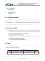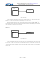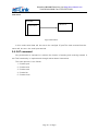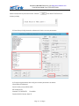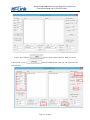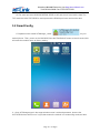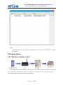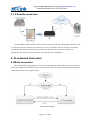
1
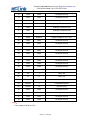
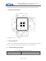
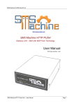
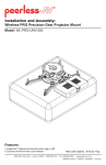
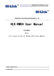
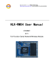
Shenzhen Hi-Link Electronic co., Ltd HLK-M30 User Manual Serial to WiFi Module Shenzhen Hi-Link Electronico.,Ltd Http://www.hlktech.com Tel:0755-23152658 Fax:0755-83575189 Catalog 1 Module Introduction .............................................................................................................................3 1.1.1 Brief Introduction ...................................................................................................................3 1.1.2 Module Features: ................................................................................................................3 1.1.3 Module Parameters: ...........................................................................................................4 1.1.4 Application ..............................................................................................................................5 1.1.5 Hardware ................................................................................................................................5 1.1.6 Pin ............................................................................................................................................6 1.1.7 Mechanical Dimension..........................................................................................................8 1.1.8 Antenna(optional) ..................................................................................................................8 1.1.8.1 External Antenna Parameter................................................................................................8 1.1.8.2 Reference on-board PCB antenna .....................................................................................9 1.1.9 General development test suit .............................................................................................9 1.2 Typecal Application .................................................................................................................12 1.2.1 HLK-M30 typecal circuit......................................................................................................12 1.2.2 MCU Simplest circuit...........................................................................................................13 2 Function .................................................................................................................................................15 2.1Wireless...............................................................................................................................................15 2.1.1 Work At STA Mode ................................................................................................................15 2.1.2 Work At SoftAP Mode ...........................................................................................................15 2.2 Work Mode: Transparent transmission ..........................................................................................16 2.3 Config Parameters............................................................................................................................17 2.4 Firmware Update ..............................................................................................................................17 2.5 GPIO ...................................................................................................................................................17 2.6 Network Protocol...............................................................................................................................18 2.6.1 Transparent transmission ..................................................................................................18 2.6.2 AT command ..........................................................................................................................20 3.Setting and using guide.......................................................................................................................21 3.1 Config by serial .................................................................................................................................21 3.1.1 Preparation work....................................................................................................................21 3.1.2 How to Connect .....................................................................................................................21 3.1.3 Test Steps: ..................................................................................................................................21 3.1.4 Communication test ..............................................................................................................24 4.1Mode conversion ............................................................................................................. 29 4.2 At command instruction .................................................................................................. 30 Appendix ................................................................................................................................................33 Page 2 / 33 Pages Shenzhen Hi-Link Electronico.,Ltd Http://www.hlktech.com Tel:0755-23152658 Fax:0755-83575189 Document history ...................................................................................................................................33 1.1.1 Brief Introduction HLK-M30 is a new low-cost embedded uart wifi module developed by Shenzhen Hi-Lin k Electronic co., Ltd This product is an embedded module based on the universal serial interface network standard, built-in TCP / IP protocol stack, enabling the user serial port, wireless network (wifi) interface between the conversions。 Through the HLK-M30 module, the traditional serial devices do not need to change any configuration data can be transmitted through the Internet network. Provide a quick solution for the user’s serial devices to transfer data via Ethernet.。 This document as familiar with the HLK-M30 module and the test suite for guidance doc ument.Please refer to<< HLK-M30 AT Command.pdf>>and<< HLK-M30 DataSheet>> 1.1.2 Module Features: ► Small size:14mm×16.5mm×2.25mm ► Low power consumption; Quick start;;network connect quickly ► Pefect support 802.11b/g/n ► Support all wifi encryption:WEP/WPA-TKIP/WPA-AES/WPA2-TKIP/WPA2-AES ► No driver need,User only need to use it as a serial port ► Support STA/AP mode ► Support TCP Server/TCP Client/UDP Server/UDP Client ► Support DHCP DNS HTTP ► Support serial at command also network at command ► Support search module in LAN Page 3 / 33 Pages Shenzhen Hi-Link Electronico.,Ltd Http://www.hlktech.com Tel:0755-23152658 Fax:0755-83575189 ► Support SmartLink function,use app to config the module connect the wireless router ► CE/FCC support,ROHS standard support Module Parameters: 1.1.3 Fig:1 HLK-M30 Module parameters Basic Wireless IEEE 802.11n、IEEE 802.11g、IEEE 802.11b 11n:up to 150Mbps Wireless Rate 11g: up to 54Mbps 11b: up to 11Mbps Channle 1-14 Frequency range 2.4-2.4835G Send Power 15-18 DBM Interface UART、GPIO Antenna Antenna Type External antenna Distance 100-300m(different situation, different transmission distance) Function WiFi mode Sta/soft ap Wireless encrypiton Encryption 64/128/WEP encryption WPA-PSK/WPA2-PSK、WPA/WPA2 Serial to Internet Max Serial rate 115200bps TCP Max connect:4 UDP Max connect:4 Others LED WIFI led operate temp:-20-70℃ Environmental Operate humidity:10%-90%RH Store temp:-40-80℃ Store humidity:5%-90%RH Page 4 / 33 Pages Shenzhen Hi-Link Electronico.,Ltd Http://www.hlktech.com Tel:0755-23152658 Fax:0755-83575189 1.1.4 Application The handheld device Remote control The consumer electronics IOT systems Industry systems Portable wireless communication product Medical equipment Led control Sensor network application Wireless printer 1.1.5 Hardware HLK-M30 top HLK-M30 back Page 5 / 33 Pages Shenzhen Hi-Link Electronico.,Ltd Http://www.hlktech.com Tel:0755-23152658 Fax:0755-83575189 1.1.6 Pin HLK-M30 PIN HLK-M30 Pin Interface Pin Function Derection 1 GPIO1 I/O General GPIO 2 GPIO0 I/O General GPIO 3 GND GND Analogue Ground 4 GND GND Analogue Ground 5 GND GND Analogue Ground 6 GND GND Analogue Ground 7 VDD2 Power In Supply Voltage, 3.3V+/-10% 8 GND GND Analogue Ground 9 ANT - Antenna Pin 10 GND GND Analogue Ground 11 GND GND Analogue Ground Page 6 / 33 Pages Description Shenzhen Hi-Link Electronico.,Ltd Http://www.hlktech.com Tel:0755-23152658 Fax:0755-83575189 12 GND GND Analogue Ground 13 GND GND Analogue Ground 14 GND GND Analogue Ground 15 AN1 - Analogue Pin(Reserved) 16 AN2 - Analogue Pin(Reserved) 17 AN3 - Analogue Pin(Reserved) 18 AN4 - Analogue Pin(Reserved) 19 VDD1 Power In Supply Voltage, 3.3V+/-10% 20 GND GND Analogue Ground 21 GND GND Analogue Ground 22 GND GND Analogue Ground 23 GND GND Analogue Ground 24 GND GND Analogue Ground 25 GND GND Analogue Ground 26 GND GND Analogue Ground 27 GND GND Analogue Ground 28 GND GND Analogue Ground 29 RST I Reset Module 30 RX I UART RX 31 TX O UART TX 32 STA_LED O Staus LED 33 ES/RST I Exit/Default/Update 34 GPIO2 I/O General GPIO 35 GND GND Analogue Ground 36 GND GND Analogue Ground 37 GND GND Analogue Ground 38 GND GND Analogue Ground Note: 1. The voltage of GPIO is 3.3V。 Page 7 / 33 Pages Shenzhen Hi-Link Electronico.,Ltd Http://www.hlktech.com Tel:0755-23152658 Fax:0755-83575189 2. When power on, the RST turn low to high voltage,make surn the RX pin at leaset 1ms。 1.1.7 Mechanical Dimension HLK-M30 detail(TOP View) Note:Module:16.5×14.1×2.25mm 1.1.8 Antenna(optional) According to the IEEE 802.11b/g/n standard requirements, and HLK-M30 need 2.4G antenn a, you can use the 2.4G external antenna or design your own onboard antenna 1.1.8.1 External Antenna Parameter Fig:2 HLK-M30 Antenna parameter Required Item Freqence Parameter 2.4^2.5GHz Page 8 / 33 Pages Shenzhen Hi-Link Electronico.,Ltd Http://www.hlktech.com Tel:0755-23152658 Fax:0755-83575189 Impedance 50 Ohm VSWR 2 (Max) return loss -10dB (Max) Connection type I-PEX or Onboard 1.1.8.2 Reference on-board PCB antenna If permit, you can use the PCB onboard antenna. See the Appendix PCB document of P CB antenna. Below is the 2.4G PCB board recommended: Note:C1, C2 do not need weld, L1 uses 0 ohm resistor or capacitor 10pF The top and back o PCB antenna part can not be connected to GND The PCB antenna must placed on the edge of the board please do impedance matching, 50 + 5 Omega impedance 1.1.9 General development test suit We provides the HLK-M30 Startkit, for the customer to quickly familiar with the product a nd in-depth application development. The figure below shows the general assessment of deve lopment and test suite appearance, users can debug module through the RS-232 serial port b y computer,and also configuration parameters…… Page 9 / 33 Pages Shenzhen Hi-Link Electronico.,Ltd Http://www.hlktech.com Tel:0755-23152658 Fax:0755-83575189 HLK-M30 StartKit StartKit Interface Fuction Interface Name Item Description DB9 J1 RS232 interface,can DC5V P1 5V input, min:3.8, max:5.5V 10pin P2 HLK-M30 module’s pin IPEX P3 Antenna IPEX SPI interface P4 Burn firmware into the flash(customs can not use) Connect to the HLK-M30 GPIO0; GPIO00 GPIO00 When GPIO0 at low voltage the LED will light up; This can test thee GPIO0 output; 3.3V power led; LED POWER POWER If this led do not light up,please check the power supply Connect to the HLK-M30 GPIO1; GPIO01 GPIO01 When GPIO1 at low voltage the LED will light up; This can test thee GPIO1 output; Page 10 / 33 Pages Shenzhen Hi-Link Electronico.,Ltd Http://www.hlktech.com Tel:0755-23152658 Fax:0755-83575189 Connect to the HLK-M30 GPIO2; GPIO02 GPIO02 When GPIO2 at low voltage the LED will light up; This can test thee GPIO2 output; WIFI LED, indicate below: Flash 2 times (cycle):The moduel staus:STA SmartConfig Staus; Flash 3 times (cycle): The moduel staus:STA Manual Staus; Extinguishing:Module have connect to the WIFI_LED Indicate LED wireless router(No communication data ); Random flash:when receiving or sending data, broadcast data, LED will flash once corresponding Fast blink:When use IoTManager config the module,when successful it will fast blink;Or there are huge Data communication Flash 4 times:The module are now get DHCP. Button Reset RESET Exit/Default Exit/Default Reset button,Press the module will reset. Short press(0.5-5s):Enter at command mode Long press(More than 6s):Back to factory Page 11 / 33 Pages Shenzhen Hi-Link Electronico.,Ltd Http://www.hlktech.com Tel:0755-23152658 Fax:0755-83575189 1.2 Typecal Application 1.2.1 HLK-M30 typecal circuit Figure 7. HLK-M30 typecal circuit <Descripiton>: Page 12 / 33 Pages Shenzhen Hi-Link Electronico.,Ltd Http://www.hlktech.com Tel:0755-23152658 Fax:0755-83575189 MCU custom’s mircrochip or serial enddevice or serial chip,the interface voltage is 3.3V TTL. RX/TX The module’s receive/send pin 74LVC3157(U3) Analog switch.This IC cannot be removed,it wil help to boot the module RESET(K2) Reset button.Press it the module will restart. WIFI_LED Indicate LED Exit/Default (K1) Short Press:exit transparent transmission. Long press(more than 6s):back to default seeting IPEX(P3) 1.2.2 Antenna interface,make sure the matching 50 + 5 Omega impedance MCU Simplest circuit Below is there is a mcu to control the hlk-m30’s RX pin,the smallest circuit.In this circuit you can remove the 74LV3157.because this IC’s fuction is replace by your mcu.Do like this: Power On → Use your mcu’s GPIO to pull down the voltage of hlk-m30’s RST and RX pin → Release RST_N pin → Wait for at least 50ms than release RX pin →Module StartUp The time between RX and RST pin is controlled by your MCU. HLK-M30 Startup sequence diagram Page 13 / 33 Pages Shenzhen Hi-Link Electronico.,Ltd Http://www.hlktech.com Tel:0755-23152658 Fax:0755-83575189 HLK-M30 Smallest Circuit Page 14 / 33 Pages Shenzhen Hi-Link Electronico.,Ltd Http://www.hlktech.com Tel:0755-23152658 Fax:0755-83575189 2 Function 2.1Wireless HLK-M30 can be configured STA or AP mode. So,there are two serial to wifi mode:serial to WIFI(STA mode) and serial to WiFi(SoftAp mode) Note: AP: The center of a wireless network node. Commonly was a wireless router. STA:Wireless node,a enddevice,like notebook,PDA are both STA device. 2.1.1 Work At STA Mode This is the basic wireless network,A ap connect all the STA device together,See the below picture, communication between the STA forward by AP,In this mode,HLK-M30 work at STA mode,by some proper settings, the data can transfer between the serial and wifi. HLK-M30 Sta Work Topology 2.1.2 Work At SoftAP Mode HLK-M30 works in AP mode, the PAD, mobile phone, computer and other equipment can directly connect to the module, That means the user can convenient to monitor their equipment。 Page 15 / 33 Pages Shenzhen Hi-Link Electronico.,Ltd Http://www.hlktech.com Tel:0755-23152658 Fax:0755-83575189 HLK-M30 SoftAP topology 2.2 Work Mode: Transparent transmission The HLK-M30 supports serial transparent transmission. This has the advantage of plug a nd play serial, to reduce the user's complexity. Module in transparent transmission mode, the user only need to configure the necessary parameters.After power on, module automatically c onnect to the default wireless network and server. Because in this mode, the module serial port always work in transparent transmission mod e, so the user just use it as a virtual serial port. In short, the module is a wireless serial por t, without any change,the user’s equipment can be easily add wireless data transceiver Transparent transmission mode is fully compatible with the user's own software platfor m, reduce integration of wireless data transmission software development. You should to cofni g the below parameters at STA Manual mode: Wireless Parameters Target AP’s SSID and SSID’S length. Target AP’s encryption Target AP’s key and key’s length TCP/UDP parameters Network Protocol Remoto IP Page 16 / 33 Pages Shenzhen Hi-Link Electronico.,Ltd Http://www.hlktech.com Tel:0755-23152658 Fax:0755-83575189 Port Serial Parameters Bandrate Data length Checksum bit Stop bit 2.3 Config Parameters HLK-M30 can config by at command,Learn more you can find << HLK-M30 AT Command V1.2>> HLK-M30 also can be configed by UDP/988 port,When you establish udp,you can send at commad by network,learn more you can see the “ at+DP” command. 2.4 Firmware Update HLK-M30 supprt serial port to update firmware.Use tool:HLK_M30_update.exe.Steps below: 1. Open HLK_M30_update.exe,Change the name of the firmware to HLK-M30.img,copy it to the same directory of the HLK_M30_update.exe tool. 2. Press C to choose update serial port. 3. Press “Enter”to let the tool to start update. 4. Connect the serial prot,Press the Exit/Reset/Update button and then power on,Wait for 1s then release,the tool will load the firmware. 5. When update complete,the module will restart. 2.5 GPIO HLK-M30 supply three GPIO to use,These GPIO can control by serial at command,and also can be controlled by UDP. HLK-M30 GPIO GPIO Function Feature Type GPI000 Output/Input High/Low Voltage Write/Read by at command I/O Page 17 / 33 Pages Shenzhen Hi-Link Electronico.,Ltd Http://www.hlktech.com Tel:0755-23152658 Fax:0755-83575189 GPI001 Output/Input High/Low Voltage Write/Read by at command I/O GPI002 Output/Input High/Low Voltage Write/Read by at command I/O For example: At+GW=0,1 GPIO0 Output High Voltage At+GR=2 Query GPIO2 Input Voltage Udp Control below: when the module have connect to the ap.Then establish udp client, prot is 988,in defa ult setting,you can send:hlkATat+GW=0,1\r,the GPIO0 will output high voltage 2.6 Network Protocol The serial to network have two method: Transparent transmission,at command 2.6.1 Transparent transmission There are 4 mode of serial to network:TCP Server、TCP Clinet、UDP Server、UDP Client。 TCP Server HLK-M30 TCP Client TCP Server TCP Client TCP Client Fig10.TCP Server In this mode,HLK-M30 is waiting for the TCP Client connection.All TCP data is sent dir ectly to the serial port.Serial data is transmitting to all TCP Clien terminal. The HLK-M30 support 4 tcp client. TCP Client Page 18 / 33 Pages Shenzhen Hi-Link Electronico.,Ltd Http://www.hlktech.com Tel:0755-23152658 Fax:0755-83575189 HLK-M30 TCP Server TCP Client Fig11.TCP Client In this mode, the HLK-M30 will connect the remote domain or ip. All TCP data is sent directly to the serial port.Serial data is transmitting to the tcp server Abnormal network disconnect can cause module active reconnection. When enable TCP reconnection function, TCP Server active disconnected, module will immediately active reconne ction, otherwise the module will not reconnect UDP Server HLK-M30 UDP Server UDP Client Fig12.UDP Server In this mode,Module will listen local udp port, Upon recevied data from this port, the dat a will be sent to the serial port, and record the distal IP,Port.The module will only record the last connection remote information. Serial receive data will be sent directly to the recorded di stal IP, Port. Page 19 / 33 Pages Shenzhen Hi-Link Electronico.,Ltd Http://www.hlktech.com Tel:0755-23152658 Fax:0755-83575189 UDP Client HLK-M30 UDP Server UDP Client Fig13.UDP Client In this mode, serial data will be sent to the configed IP, port.The data recevied from the server will be sent the serial port terminal. 2.6.2 AT command We provides the at command to achieve the function of sending and receiving network d ata. This functionality is implemented through socket related instructions. The basic process is as follows 1)Socket open 2)Socket write 3)Socket read 4)Socket list 5)Socket close Page 20 / 33 Pages Shenzhen Hi-Link Electronico.,Ltd Http://www.hlktech.com Tel:0755-23152658 Fax:0755-83575189 3.Setting and using guide 3.1 Config by serial 3.1.1 Preparation work Hardware: HLK-M30 module HLK-M30 motherborad 5V power Serial cable Wireless router Cumputer Software HLK-M30_CONFIG tool Serail&TCP_UDP test tool 3.1.2 How to Connect Below is the general development kit for communication test. Need a serial computer, no serial port machine can use a USB to serial cable. Connections are as follows: Connection of the testboard 3.1.3 Test Steps: 1.PowerOn the wireless router.We set the wireless parameter as below: Page 21 / 33 Pages Shenzhen Hi-Link Electronico.,Ltd Http://www.hlktech.com Tel:0755-23152658 Fax:0755-83575189 Wireless name:(ssid):HI-LINK_Guest Encryption:WPA2_AES Key:hlktech123 DHCPD:191.168.16.100 网关:192.168.16.254 DNS:192.168.16.254 2,Connect the DB9 of startkit with your computer’s DB9, then power on,the wifi led will flash. 3.Open“HLK-M30_CONFIG-English”, ,Software interface as follows: HLK-M30_CONFIG Interface 4,Chose the right COM port ,Press the “Exit/Default” button on the Page 22 / 33 Pages Shenzhen Hi-Link Electronico.,Ltd Http://www.hlktech.com Tel:0755-23152658 Fax:0755-83575189 starkit board,and then press the button “Search” ,it will back:Find Device at COM1(115200) 5,Press QueryConfig button,the software will list the current parameters 6,Change the parameters.We config the module parameters as below: Work Mode:STA Manual, Ssid:HI-LINK_Guest WPA2 /AES KEY:hlktech123、 Network:TCP SERVER. Port:8080 Disable DHCP,Choose Staic IP. Page 23 / 33 Pages Shenzhen Hi-Link Electronico.,Ltd Http://www.hlktech.com Tel:0755-23152658 Fax:0755-83575189 7,Press Commit ,the command will send to the module. Command and respongse area will display the status of command will send and execution. 3.1.4 Communication test 8,Till now the module have connect to HI-LINK_Guest.So we open serial and TCP/UDP test tool to test the communication. Page 24 / 33 Pages Shenzhen Hi-Link Electronico.,Ltd Http://www.hlktech.com Tel:0755-23152658 Fax:0755-83575189 9.Open the COM port module,press connect ,type in the ip address and the 8080 port of the ,and send data to each other,you can see both have received data Page 25 / 33 Pages Shenzhen Hi-Link Electronico.,Ltd Http://www.hlktech.com Tel:0755-23152658 Fax:0755-83575189 10,The serial port send:HLK-M30 SERIAL SEND to wifi,and the wifi received the data.The TCP send:HLK-M30 TCP SEND to serial port and the RS232 port have received the data. 3.2 SmartConfig 1 Preparation work:Install“IoTManager_v0.96” on your android phone .Then, power on the HLK-M30,Press the”Exit/Default” button at least 6 second,this will make the module return to factory setting. 2,Open IoTManager,type in the target wireless router’s ssid and passwork, observe the WIFI-LED blink two times out of a cycle,that means the module is in smartconfig mode,and then Page 26 / 33 Pages Shenzhen Hi-Link Electronico.,Ltd Http://www.hlktech.com Tel:0755-23152658 Fax:0755-83575189 press start button: ,this will config the module connect to the wireless router,when the WIFI-LED is quickly flashing,that mean the module have connected to the router. 3,Let you notebook also connect to the same router,Open our search tool:HLK-M30_Discover ,Press “Discover” button from our company,See below: Page 27 / 33 Pages ,You can find all the wifi modules Shenzhen Hi-Link Electronico.,Ltd Http://www.hlktech.com Tel:0755-23152658 Fax:0755-83575189 Note: HLK-M30 factory setting is Smart Config.When power on,you can use this tool to config the module 3.3 Applications 3.3.1 Wireless remote control In this application,the HLK-M30 in STA mode,connect to AP, the HLK-M30 serial connected to user’s equipment. Mobile phone, PAD or computer is connected to the AP, and then through the wireless network to control the user’s equipment. Page 28 / 33 Pages Shenzhen Hi-Link Electronico.,Ltd Http://www.hlktech.com Tel:0755-23152658 Fax:0755-83575189 3.3.2 Remote connection The HLK-M30 module as STA, connect to the Internet through the gateway(AP). Module is set to TCP Client, points to the server, the server is set to TCP Sever.The user device is connected to HLK-M30 through the serial port, and its data can be sent to the server to process and storage.The service can send commands to control the user’s equipment 4. At command Instruction 4.1Mode conversion When HLK-M30 module power on,it will enter transparent transmission mode,you can pull down the voltage of the ES/DST pin to let the module enter AT mode.Transparent transmission mode and at mode can change like this: Serail Port Work Mode Page 29 / 33 Pages Shenzhen Hi-Link Electronico.,Ltd Http://www.hlktech.com Tel:0755-23152658 Fax:0755-83575189 When power on,the module will check the config of the network,if it can connect to the internet it will enter transparent transmission,if not,it will enter at command mode. The method of change the transparent transmission mode to at command mode:pull down the voltage of the ES/RST pin more than 0.5s less than 5s,it will enter at command mode.If you pull down the ES/RST pin more than 6s,the module will back to factrory config. Send at+TS=1,the module will enter transparent transmission mode. 4.2 At command instruction At at command mode,you can config the module by at command,the at format like below: at+[command]=[value]\r, There need ” \r”, otherwise it will be considered wrong at instruction. According to the different command module will return a different value For example:”at+UIp=192.168.11.133\r” Set the remote ip address:192.168.11.133。 ”at+UIp=?\r” Query the remote ip address 。 at command below:( Instruction is case sensitive) KeyWord Function WA Wifi mode,ap/sta WM Wifista method:manual or smartconfig Sbssid set target ap bssid Sssid set target ap ssid Sssidl set target ap ssid length Sam set target ap encryption method Spw set target ap key Spwl set length of target ap key WC calculation PMK dhcp set dhcp or static ip static ip mask Static mask dns Static DNS gw Static gateway Ub Set uart bandrate Ud Set uart datalength Up Serial parity bit Us Serial stop bit length UType UIp URPort Set TCP or UDP Set remote ip address Set remote port Page 30 / 33 Pages Shenzhen Hi-Link Electronico.,Ltd Http://www.hlktech.com Tel:0755-23152658 Fax:0755-83575189 ULPort Set local port UPL Set or query data length of automatic framing UPT Set or query period of automatic framing UPT2 Set or query Interval period of automatic framing DP Prefix data for UDP/988 port executes the at command DE UDP/988 port executes the at command enable or disable Rb Reboot the module ver version Df Back to default setting SO Socket open SC Socket close SL Socket check SW Socket send SR Socket read DR Domain name resolution GW GPIO write GR GPIO read TS Transparent ransmission change mac Get mac address Note:The at instruction are case sensitive. "at" the two character is lowercase。 More details of AT Command,you can refer to:<< HLK-M30 AT Command V1.2>> HLK-M30_CONFIG tool Details: Page 31 / 33 Pages Shenzhen Hi-Link Electronico.,Ltd Http://www.hlktech.com Tel:0755-23152658 Fax:0755-83575189 Interface description: 1. Choose Com port 2. Search module button 3. Choose module’s work mode 4. Wireless Parameters 5. Choose network Protocol 6. Serial port parameters 7. Remote/Local port 8. Network IP 9. Submit the configure button 10. Query the configure button 11. Enter the transparent transmission button 12. Back to factory setting button 13. Waiting to send AT command zone 14. At command execue returns area 15. Save user parameter button. Page 32 / 33 Pages Shenzhen Hi-Link Electronico.,Ltd Http://www.hlktech.com Tel:0755-23152658 Fax:0755-83575189 Appendix Document history version Records Date V1.1 Draft version 2014-8-10 V1.2 Add UDP at command decription 2014-9-20 Page 33 / 33 Pages