1
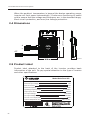
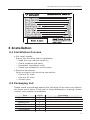
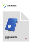
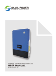
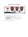
TM
SAMIL POWER
Expert for PV Grid-tied Inverters
SolarPond
Product Manual
SP-SP-1.0-EN
Copyright Declaration
The copyright of this manual belongs to Samil Power Co., Ltd. Any corporation
or individual should not plagiarize, partially copy or fully copy it (including
software, etc.), and should not reproduce or distribute it in any form or by any
means. All rights reserved. Samil Power reserves the right of final interpretation.
This manual changes according to user’s or customer’s feedback. Please check
our website at www.samilpower.com for the latest version.
01
CONTENTS
1 Notes on This Manual
1.1
1.2
1.3
1.4
1.5
Scope of Validity
Target Group
important Safety Information
Important Safety Instructions
Symbols Used
2 The SolarPond series Inverter System
2.1
2.2
2.3
2.4
2.5
New Features
The Advantage of SolarPond MPPT
Protection Function
Dimension
Product Label
3 Installation
3.1
3.2
3.3
3.4
Installation Process
Packaging List
Safety Instruction
Installation Tools
05
05
05
05
05
05
05
07
07
08
08
09
10
19
19
21
22
4 Commissioning
15
5 Troubleshooting
15
5.1 Troubleshooting an Inoperable Inverter
5.2 Disconnecting the Inverter from the PV Module
5.3 Troubleshooting Tips
6 Technical Data
6.1
6.2
6.3
6.4
DC Parameters
AC Parameters
Efficiency
General data
7 Appendix
02
19
19
21
15
22
23
24
25
27
Notes on This Manual
1 Notes on This Manual
This manual is an integral part of the inverter. Please read the product
manual carefully before installation, operation or maintenance. Keep this
product manual for future reference.
1.1 Scope of Validity
This product manual describes the assembly, installation, commissioning,
and maintenance of the following Samil Power SolarPond.
SolarPond 240HF-US
SolarPond240HF-AU
1.2 Target Group
This manual is meant for qualified electricians. The tasks described in
this manual must only be performed by qualified electricians.
1.3 Important Safety Information
Before installation or operation, please read the manual, or contact the
local distributor. Please visit the company website: www.samilpower.com
for more information.
1.4 Important Safety Instructions
When using the product, please remember the following instructions:
● Read all instructions and cautionary markings on the SolarPond series
inverter, and all appropriate sections of this guide.
● Perform all electrical installations in accordance with all local and National
Electrical Codes (NEC), like ANSI/NFPA 70.
● Only qualified personnel should install and/or replace SolarPond series
inverters.
● Do not attempt to repair the SolarPond series inverters; it contains no
user serviceable parts. If it fails, please return the unit to your distributor
for maintenance. Tampering with or opening the SolarPond series inverters
will affect the warranty.
● Connect the SolarPond series inverter to the electrical utility grid as per
local regulations which may include prior written approval from the
utility company.
1.5 Symbols Used
Some symbols are used in this manual in order to ensure personal and
property safety. Please read and understand the following symbols
carefully.
03
Notes on This Manual & The SolarPond series Inverter System
Danger!
Danger indicates a hazardous situation, if not avoided,
will result in death or serious injury.
Note!
Note provides tips about the optimal operation when
using the product.
2 The SolarPond series Inverter System
The SolarPond series inverter is a PV micro inverter which converts the DC
power of a PV generator into AC power and feeds it into the public grid.
The key elements of a SolarPond series inverter based system are:
● SolarPond series inverter
● SolarWatcher100-zigbee (SW100)
● SolarWatcher Manager
Photovoltaic modules
Microv-inverters
SolarWatcher100
SolarRepeater(optional)
Ethernet cable
Meter
Router
SolarWatcher Manager
This integrated system maximizes energy harvest, increases system
reliability, and simplifies design, installation and management.
04
The SolarPond series Inverter System
2.1 New Features
●
●
●
●
●
●
●
●
●
●
Max. efficiency of 96%
EURO Efficiency of 94.5%
CEC efficiency of 95.5%
MPPT efficiency of 99.5%
HF transformer
Advanced monitoring
Outdoor installation&wide operate temperature
Excellent protection
Long life design with 25-year warranty
Simple installation
2.2 Advantage of SolarPond MPPT
The SolarPond series inverter maximizes energy production from your
photovoltaic (PV) array. Each SolarPond series inverter is individually
connected to one PV module in your array. This unique configuration
means that an individual Maximum Power Point Tracker (MPPT) controls
each PV module. This insures that the maximum power available from
each PV module is exported to the utility grid regardless of the
performance of the other PV modules in the array. That is, although
individual PV modules in the array may be affected by shading, soiling,
orientation, or module mismatch, the SolarPond series inverter ensures
top performance of each associated PV module. The result is maximum
energy production from your PV system.
2.3 Protection Function
Anti-islanding protection
When the local power grid shuts down because of failure or equipment
maintenance, SolarPond series inverter should be physically disconnected
safely so as to protect any personnel working on the grid, in full compliance
with the applicable prevailing national standards and regulations.
Grounding fault
Inverters with direct inputs from a grounded photovoltaic array or arrays
need to be provided with a ground-fault detector/interrupter (GFDI).
The GFDI is capable of detecting ground fault, providing an indication of
the fault, interrupting the flow of fault current, and either isolating the
faulty array section or disabling the inverter to cease export of power.
The GFDI is used only in the SolarPond 240HF-US.
More equipment protection
SolarPond series inverter can run safely in any working condition because
of the following protections:
05
The SolarPond series Inverter System
When the ambient temperature is beyond the design operating range,
inverter will limit power automatically; Continuous monitoring of power
grid to ensure that the voltage and frequency are in the standard range;
short-circuit protection, and over/low voltage protection .
+
-
230.0mm
170.0mm
2.4 Dimensions
AC
34.5mm
2.5 Product Label
Product label attached to the back of the inverter provides basic
information of the unit. Do pay special attention to the type of inverter
and other specifications.
Model:SolarPond-US
MPPT range at full load:
Maximum input voltage:
Max. DC current:
Nominal frequency:
Operating frequency range:
Output power factor:
AC output Voltage:
AC output voltage range:
48V
>9.5A
60HZ
59.3-60.5Hz
0.95min
240V/208V
211-264V/183-229V
AC max. cont. output power:
240W
Ambient temperature range:
-40℃ to +65℃
P
06
27~40V
The SolarPond series Inverter System & Installation
3 Installation
3.1 Installation Process
● Pre install checks
Ensure the following before installation:
√ Read the user manual carefully;
√ Check products and parts;
√ Inspection installation tools;
√ Check the installation environment.
● Electrical connection
Work involved in the electrical connection:
√ Connect DC side;
√ Connect AC side;
√ Ground joint.
3.2 Packaging List
Please check the package against the following list to make sure that all
the items are in place. If any part is found damaged or missing, please
contact your supplier immediately.
Item
Inverter
Set of screw
Packing list
Manual
Warranty card
Certification
Value
1
1
1
1
1
1
Comments
Up to UL1741 and AS standard
07
Installation
3.3 Safety Instruction
SolarPond series inverter is easy to install. Each inverter can be quickly
mounted on the PV racking, directly beneath each PV module. DC cables
connecting the PV modules to inverters carry low DC voltage thereby
making this system safer than conventional PV systems having much
higher voltages.
● Before installing the SolarPond series inverter, read all instructions and
cautionary markings in the user manual, on the SolarPond series
inverter, and on the photovoltaic array.
● Perform all electrical installations in accordance with all local electrical
codes like National Electrical Code (NEC),and ANSI/NFPA 70.
● Connect the inverter to the electrical utility grid as per local regulations
which may include prior approval from the utility company.
● Only qualified personnel should connect the inverter to the electrical
utility grid.
● Be aware that installation of this equipment includes risk of electric
shock. Normally grounded conductors may become un-grounded and
energized when a ground fault is indicated.
3.4 Installation Tools
Following tools and parts are needed for installation.
●
●
●
●
●
●
Junction box
Grounding cable
Screwdriver
1/2 and 9/16 inch socket wrenches
Wire cutters
Wire strippers
3.5 Installation
Installing the SolarPond series inverter System involves five key steps:
A. Installing the junction box
B. Attaching the SolarPond series inverter to the racking
C. Grounding the system
D. Connecting AC side
E. Connecting to the PV modules
A. Installing the junction box
Step 1: Mount the junction box at the end of rack, ensure that the hole
on the junction box match the corresponding hole on the rack.
Step 2: Insert the T-headed bolt through junction box and rack holes
and tighten the flange nut.
08
Installation
T bolt component
B. Attaching the SolarPond series inverter to the racking
Step 1: Mount the SolarPond series inverter at the appropriate location
of the rack.
Step 2: Insert the T-headed bolt through junction box and rack holes
and tighten flange nut.
Step 3: Insert the T-headed bolt with grounding clamp through junction
box and rack holes, and tighten flange nut.
T bolt component
09
Installation
Note!
Note provides tips about the optimal operation when
using the product.
C. Grounding the system
Step 1: Fix the copper wire into grounding clamp.
Step 2: Tighten the bolt of grounding clamp to fix the copper wire.
Earthing lug component
D. Connecting AC side
Step 1: Connect the first inverter to the first junction box (closest to
junction box).
Step 2: Repeat for each the inverter.
Step 3: Cover the last connector to protect it.
Connect
10
Installation
One junction box connects up to 24 inverters in a 208V
AC mode and 17 inverters in 240V AC mode. Please
ensure that the Copper wire used can operate at the
maximum current.
The minimum-bending radius of AC wire is 40mm.
E. Connecting to the PV modules
Step 1: Connect the positive cable of PV modules to the negative cable
of the inverter.
Step 2: Connect the negative cable of PV modules to the positive cable
of the inverter.
Step 3: Then install the PV module.
11
Installation & Commissioning
If the wire is too long, please fasten it to the rack by
strapping.
The minimum-bending radius of DC wire is 32.5mm.
4 Commissioning
Connect the inverter to the electrical utility grid as per
local regulations which may include prior approval from the
utility company.
Be aware that only qualified personnel must connect the
inverter to the electrical utility grid.
Ensure that all AC and DC wiring is correct. Ensure that
none of the AC and DC wires are pinched or damaged.
Ensure that all junction boxes are properly closed.
To commission the inverter PV system:
1. Turn ON the AC switch on each AC circuit junction box.
2. Turn ON the main utility-grid AC circuit breaker. Your system will start
producing power after a five-minute wait time.
3. Verify operation and production by reading the display on the LCD panel
of the SW100. Please refer to the SW100 Installation and Operation Manual
for information on the SW100.
12
Troubleshooting
5 Troubleshooting
Do not attempt to repair the inverter; it contains no userserviceable parts. If it fails, please return the unit to your
distributor for maintenance.
Be aware that only qualified personnel should troubleshoot
the PV array or the inverter.
The inverters are powered both by AC power from the
utility grid and DC power from the PV modules. Make sure
you disconnect both the AC and the DC connections and
reconnect either AC or DC power to hear the six start-up
beeps.
Always disconnect AC power before disconnecting the PV
module wires from the inverter. The AC connector of the
first inverter in a branch circuit is suitable as a disconnecting
means once the AC branch circuit breaker in the load
center has been opened.
5.1 Troubleshooting
To troubleshoot in case of a faulty inverter, follow the steps in the order
shown:
1. Check the connection to the utility grid. Verify the grid voltage and
frequency to ensure that these are within allowable ranges shown in
the Technical Data section. Verify utility power is present at the inverter
in question by removing AC, then DC power. Never disconnect the DC
wires while the inverter is producing power. Re-connect the AC power
conductor and listen for six short beeps.
2. Check the AC branch circuit interconnection between all the inverters.
Verify each inverter is energized by the utility grid as described in the
previous step.
3. Make sure that all the AC switches in the junction boxes are functioning
properly and are closed.
4. Verify the PV module DC voltage is within the allowable range shown
in the Technical Data section.
5. Check the DC connections between the inverter and the PV module.
6. If the problem persists, please call customer support at SamilPower.
5.2 Disconnecting the Inverter from the PV Module
To ensure that the inverter is not disconnected from the PV modules
13
Troubleshooting
under load, adhere to the following disconnection steps in the order
shown:
1.
2.
3.
4.
Turn off the AC disconnect on the AC branch circuit junction box.
Turn off the utility-grid AC circuit breaker.
Disconnect the AC branch circuit connector(s).
Using a DC current probe, verify there is no current flowing in the DC
wires between the PV module and the inverter.
5. If there is measurable DC current, cover the PV module connected to
the inverter with an opaque material.
6. Disconnect the PV module DC wire connectors from the inverter.
7. Remove the inverter from the PV array racking.
5.3 Troubleshooting Tips
Alarm message Alarm code
AC Frequency
Out of Range
E001
Causes and solutions
The grid frequency is too high or too low,
beyond normal working range.
In this situation, no action is normally
needed as the inverter will be connected
to the grid automatically when the grid
frequency returns to normal range.
If fault continues even after grid supply
is resitred, please contact Samil customer
service hotline or customer service mailbox.
AC Voltage
Out of Range
E002
The grid voltage is too high or too low,
beyond normal working range.
In this situation, no action is normally
needed as the inverter will be connected
to the grid automatically when the grid
voltage returns to normal range.
If fault continues even after grid supply
is resitred, please contact Samil customer
service hotline or customer service mailbox.
DC Over
Voltage
E003
DC voltage of photovoltaic panels is too
high.
(1) Photovoltaic panels and inverter are
not compatible. Please check the
technical parameters of photovoltaic
panels and inverter.
(2) Reflection from snow. When light level
14
Troubleshooting
Continued:
returns to normal, inverter will be
connected to the grid automatically.
(3) If fault continues, please contact Samil
customer service hotline or customer
service mailbox.
DC Under
Voltage
E004
DC voltage of photovoltaic panels is too
low.
(1) Photovoltaic panels and inverter are
not compatible. Please check the
technical parameters of photovoltaic
panels and inverter.
(2) Poor sunlight. When light returns to
normal inverter will be connected to
the grid automatically.
(3) Photovoltaic panels may be shaded.
Please prevent shading.
(4) If fault continues, please contact Samil
customer service hotline or customer
service mailbox.
GFDI Fault
E005
If GFDI is more than 1A, inverter will stop
generating power.
(1) The photovoltaic panels are covered
with snow or inverter is operating in
damp weather. Please Take necessary
action to address the problem.
(2) Please contact PV technician to test
ground impedance of photovoltaic
panels. If the ground impedance is
more than 1k ohm, photovoltaic panels
may need to be changed.
(3) If fault continues, please contact Samil
customer service hotline or customer
service mailbox.
Grid supply
failure
E006
Grid supply is lost
No action is normally required as the
inverter will restart when the grid voltage
returns to normal range.
15
Troubleshooting
Continued:
If fault continues, please contact Samil
customer service hotline or customer
service mailbox.
Grid Instability
E007
Grid voltage is instable .
The followings could cause grid voltage
instability
(1)
(2)
(3)
(4)
Grid voltage out of range.
Grid frequency out of range.
Grid supply failure
Serious grid voltage distortion .
No action is normally necessary as the
inverter will be connected to the grid
automatically when the grid supply returns
to normal.
If the fault continues please contact Samil
customer service hotline or customer
service mailbox.
Over
Temperature
E008
Working temperature is too high.
(1) The ambient temperature is very high.
If possible shift inverter to a cooler
location.
(2) Inverter output too high.
(3) No action necessary as the inverter
will work normal when the conditions
returns to normal. If the fault continues
please contact Samil customer service
hotline or customer service mailbox.
6 Technical Data
You must match the DC operating voltage range of the PV
module with the allowable input voltage range of the inverter.
The maximum open circuit voltage of the PV module must
not exceed the specified maximum input voltage of the
inverter.
16
Technical Data
6.1 DC Parameters
SolarPond
240HF-US
SolarPond
240HF-AU
250
250
MPPT Voltage Range at Full Load[V]
27~40
27~40
Operating voltage Range[V]
21~48
21~48
Inverter Model
Max DC power[W]
Maximum input voltage[V]
48
48
Turn On Voltage Range[V]
25~48
26~48
Max DC Input Current (RMS)[A]
9.5
9.5
Max Short Circuit Current[A]
15
15
Ground fault protection[mA]
1000
Maximum input source back-feed
current to input source[A]
0
0
SolarPond
240HF-US
SolarPond
240HF-AU
6.2 AC Parameters
Inverter Model
240
240
Output Power Factor[%]
>95%
>95%
Nominal Voltage Range
at 240V nominal[V]
AC 211~264
Nominal Voltage Range
at 208V nominal[V]
AC 183~229
230
(Nominal
Voltage)
Extended Voltage Range
at 240V nominal[V]
AC 206~269
Extended Voltage Range
at 208V nominal[V]
AC 179~232
Max AC output power(-40 to 65℃)[W]
Maximum AC Output current
at 240V nominal[A]
1.14
Maximum AC Output current
at 208V nominal[A]
1.3
Nominal Frequency[Hz]
60
207~264
(Nominal
Voltage Range)
1.16
(Maximum AC
Output current)
50
17
Technical Data
Continued:
Nominal Frequency Range[Hz]
59.3~60.5
Extended Frequency Range[Hz]
59.2~60.6
47.5~52.5(Nominal
Frequency Range)
20
20
Maximum AC output
over current protection[A]
Maximum AC output fault current
& duration[A]
1.4Arms over
1.5Arms over
3 cycles,
3 cycles,
32.8Apeak
37.8Apeak
1.74ms duration 1.74ms duration
High AC Voltage trip limit accuracy[%]
±2.5%
±2.5%
Low AC Voltage trip limit accuracy[%]
±2.5%
±2.5%
Frequency trip limit accuracy[Hz]
±0.05
±0.05
Trip time accuracy[ms]
±16.7
±20
Maximum inverters per 20amp
AC branch circuit at 240V nominal
17
Maximum inverters per 20amp
AC branch circuit at 208V nominal
24
17
(at 230V
nominal)
Total Harmonic Distortion of
current on input (THDI)
<5%
<5%
50
50
SolarPond
240HF-US
SolarPond
240HF-AU
MAX Efficiency[%]
96.0
96.0
EURO Efficiency[%]
95.0
95.0
Power consumption at night[mW]
6.3 Efficiency
Inverter Model
CEC Efficiency[%]
MPPT Efficiency[%]
18
95.5
95.5
>99.5
>99.5
Technical Data & Appendix
6.4 General Data
SolarPond
240HF-US
SolarPond
240HF-AU
Ambient Temperature Range[℃]
-40 to +65℃
-40 to +65℃
Ambient Temperature Range
at Full Load[℃]
-40 to +65℃
-40 to +65℃
Operating Temperature Range
(internal) [℃]
-40 to +85℃
-40 to +85℃
Storage Temperature Range[℃]
-40 to +65℃
-40 to +65℃
Inverter Model
Maximum Operating Altitude
without Derating[m]
Noise[dB]
2000m 3000m 2000m 3000m
with derating
with derating
<30dB
<30dB
7 Appendix
208 V mode system wiring diagram
:GROUND
:L1
:L2
:L3
:NEUTRAL
1
2
3
4
5
1
MICRO INVERTER1
2
3
1
METER
PV CELL1
4
5
AC JUNCTION BOX
PHASE :L1,L2
PV CELL2
MICRO INVERTER2
PHASE :L1,L3
PV CELL3
MICRO INVERTER3
PHASE :L2,L3
AC CABLE
L1 L2 L3 N PE
2
1
5
AC DISTRIBUTION PANEL
SOCKET
SolarWatcher 100
19
Appendix
240V mode system wiring diagram
PV CELL1
2
3
4
1
MICRO INVERTER1
2
3
1
METER
L1
L2
N
PV CELL2
PV CELL N
:GROUND
:L1
:L2
:NEUTRAL
1
MICRO INVERTER2
MICRO INVERTER N
AC CABLE
4
AC JUNCTION BOX
PE
2
1
4
SOCKET
SolarWatcher 100
AC DISTRIBUTION PANEL
230V mode system wiring diagram(Australia)
PV CELL1
1
2
3
METER
MICRO INVERTER1
L
N
1
MICRO INVERTER N
AC CABLE
AC JUNCTION BOX
2
1
3
20
MICRO INVERTER2
3
PE
AC DISTRIBUTION PANEL
PV CELL N
:GROUND
:L
:NEUTRAL
1
2
PV CELL2
SOCKET
SolarWatcher 100
SAMIL POWER CO., LTD.
Marketing & Sales Office
Factory
Add: No.52, Huigu Innovation Park, Huishan District,
Add: No.66 Taihangshan Road,
Tel:
Wuxi, Jiangsu Province, P.R.China 214174
Suyu Economic Development Zone,
+86 510 83593131
Suqian City, Jiangsu Province,
Fax: +86 510 81819678
P.R.China 223800
E-mail: [email protected]
Tel:
+86 527 88754666
http://www.samilpower.com
Fax: +86 527 84453877