1
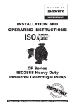
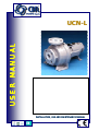
USER MANUAL UCN-L INSTALLATION, USE AND MAINTENANCE MANUAL EN ® MIEN006-04 UCN-L MIEN006-04 First edition (july. 2002) This manual is published by CDR Pompe S.p.A. Without any warranty. Improvements and changes to this manual necessitated by typographical errors, inaccuracies of current information, or improvements to equipment, may be made by CDR Pompe S.p.A. at any time and without notice. Such changes will, however, be incorporated into new editions of this manual. Drawings and technical instruction for assembling, installation and maintenance of the machinery including the manual and information provided with the machine are exclusive property of C.D.R. Pompe S.p.A. The same can not be transferred to any third party without prior written authorizations by C.D.R. Pompe S.p.A.. All rights reserved. CDR Pompe S.p.A., 2002 Trademarks Viton® is a registered trademarks of DuPont Dow Elastomers. Pag. - 2 CDR Pompe S.p.A. – UCN-L User Manual ® MIEN006-04 1. General Information 1.1. 1.2. 1.3. 1.4. 1.5. 1.6. Introduction ………………………………………………………….. Purpose of the manual ………………………………………….... Application fields .…………………………………………………... Copyright .………………………………………………………….... Pump Identification .……………………………………………….... Warranty .………………………………………………………..….. 2. Safety 2.1. 2.2. 2.3. 2.4. 2.5. 2.6. 2.7. Page Page Introduction ……………………………………………………….. Symbols and signs ………………………………………………… Operator qualification and training ……………………………… Safety instructions ………………………………………………… Noise level …………………………………………………………... Modifications and spare parts ……………………………………. Safety in explosive environments ………………………………………… 3. Packaging and Transport Page 5 INDEX 5 5 5 6 6 7 9 9 9 10 10 11 11 11 13 3.1. Packaging ………………………………………………………….. 13 3.2. Shipping and receiving .………………………………………….. 13 3.3. Storage ……………………………………………………………. 14 4. Structural Description Page 15 4.1. Description ………………………………………………………….. 15 4.2. Construction and Operating ..……………………………………….. 16 5. Installation and Assembly Page 5.1. General instructions ………………………………………………….. 5.2. Installation ……………………………………………………………. 5.3. Pump-Motor unit alignment ….……………………………………… 5.3.1. General information ..……...………………………………... 5.3.2. Alignment verification ……………………………………… 5.3.3. Angular Alignment …..……………………………………… 5.3.4. Lateral Alignment ..………………………………………… 5.3.5. Correction of Misalignments …..……………………………. 5.4. Plumbing …………….……………………………………………… 5.4.1. General instruction ..…..……………………………………... 5.4.2. Max. stress on nozzles …………………….……………… 5.4.3. Delivery piping ………………………………………………. 5.4.4. Suction piping ……………………………………………..... 5.4.5. Instruments ……….…………………………………………… 5.5. Connecting the Motor …………….………………………………… CDR Pompe S.p.A. –UCN-L User Manual 19 19 19 20 20 20 20 21 21 20 20 20 20 21 21 20 Pag. - 3 MIEN006-04 ® INDEX 6. Starting and Stopping Page 25 6.1. General prescriptions …………………………………………….. 6.2. Starting the pump …………………………………………………. 6.3. Re-starting after power shut-off ………..………………………… 6.4. Stopping the pump ………………………………………………… 6.5. Periods of long inactivity …………………………………………. 6.5.1. The pump remains installed ..…………………………… 6.5.2. The pump is removed and stored ………………………… 7. Maintenance Page 27 7.1. General information …..………...……………………………….. 7.2. Pump handling ………..……………………………………………. 7.3. Dismantling the pump …………..………………………………… 7.4. Maintenance schedule …...……………………………………… 7.5. Wear parts check and replacement .……………………………. 8. Troubleshooting 25 25 26 26 26 26 26 27 27 28 30 30 Page 31 8.1. General Information …..………...……………………………….. 31 8.2. Assembling Pump ……….………………………………………. 32 9. Tables and Charts Page 35 9.1. Features table ………..…………...……………………………….. 35 Pag. - 4 CDR Pompe S.p.A. – UCN-L User Manual ® MIEN006-04 General information 1.1. Chapter 1 Introduction This manual refers to centrifugal pumps mechanical seal model UCN-L produced according to in agreement to DIN24256 is ISO2858. C.D.R. Pompe S.p.A. would like to thank you for choosing our products. We believe that with a correct installation and proper use of this product you will achieve the best results, therefore please read this manual carefully before carrying out any operations on the pump-motor unit. Any use other than that described herein is considered incorrect and therefore C.D.R. Pompe S.p.A. shall not be held responsible for any damages to people or things. In case of doubt or enquiries, please apply to our technical service directly at the following address: C.D.R. Pompe S.p.A. Via Togliatti 26/A I-20030 Senago, MI Tel. +39 02 990 1941 Fax: +39 02 998 0606 [email protected] 1.2. UK Branch: CDR Pumps (UK) Ltd. Finedon Road Ind. Est Wellingborough Northants – NN8 4ST Tel. 01933 226 200 Fax: 01933 226 225 Purpose of the Manual This manual supplies the user of the pump-motor unit manufactured by C.D.R. Pompe S.p.A. the necessary information for the correct installation, use and maintenance in compliance with safety conditions prescribed by the current CE standards. 1.3. Application Fields The centrifugal pumps to mechanical seal model UCN-L are designed to transfer a variety of different liquids maximum system pressure as specified on chapter 9 “Tables” Obviously such figures depend on the size of the pump, the type of materials used and the pumped liquid. The operating conditions and hence the real field of use for which the type of pump and its components have been selected, are described in the technical sheet released with the order. If you need to change the type of service for which the pump has been selected and purchased, please contact C.D.R. Pompe S.p.A.’s technical service before any change is applied. The user is responsible for any damage caused to person or property if such damage is determined by non-compliance with the operating conditions agreed at the time of the Order Confirmation and the information contained in this manual. CDR Pompe S.p.A. –UCN-L User Manual Pag. - 5 MIEN006-04 ® It is also Customer’s responsibility to: Verify the suitability of the pump-motor unit to the working environment Provide operators with proper protection and safety devices. Provide operators/users with information concerning proper use of the pump. 1.4. Copyright This manual and the information herein is sole property of C.D.R. Pompe S.p.A., who reserves the right to change its contents without prior notice. It contains technical information and drawings that are property of C.D.R. Pompe S.p.A. No parts of this manual can be reproduced in any form without prior written consent from C.D.R. Pompe S.p.A. The ® Logo and name are registered trademarks of C.D.R. Pompe S.p.A. The names ILS (Integrated Lining System) are registered Trademarks and Trade Name of C.D.R. Pompe S.p.A. 1.5. Pump Identification Each pump is provided with a data plate containing the following information: 1234567- Pump model Serial No. Item (when requested) Capacity Head Material in contact with liquid Diameter of impeller 1 3 2 5 4 6 7 For applications with Ex-proof requirements, an additional label is placed on the pump. On the label you will find the following information: 1. 2. 3. 4. CE logo Ex protection Logo Equipment Group Explosive Atmosphere class: G = Gas D = Dust 5. Temperature class: T6 = up to 85°C T5 = from 85°C to 100°C T4 = from 100°C to 135°C T3 = from 135°C to 200°C T2 = from 200°C to 300°C II 2 G D T 4 8 9 10 11 12 In case of requests for spare parts, assistance or information concerning the pump supplied, the serial number must be provided. Please make sure to have the serial number handy before contacting CDR Pompe S.p.A. service Pag. - 6 CDR Pompe S.p.A. – UCN-L User Manual ® MIEN006-04 1.6. Warranty General Terms & Conditions 1. General Condition: The following terms and condition apply to the sale of machinery, components and related services and products, fabricate to C.D.R. Pompe S.p.A. 2. C.D.R. Pompe S.p.A. (the manufacturer) guarantees that only high quality materials are used in the construction of the pumps and that machining and assembly are carried out to the highest standards. 3. The manufacturer warrants its products as being free of defects in material, design and workmanship at the time of original purchase and for a period of 12 (twelve) months from the date of delivery unless otherwise specifically stated in writing and anyway within 18 months from the data of shipment, whichever comes first respectively. The guarantee covers the replacement or repairing of any parts, which is documentedly faulty due to construction or assembling, with new or repaired parts free of charges delivered by C.D.R. Pompe S.p.A. Parts subjected to normal tear and wear are not covered by the warranty. 4. This warranty is not applicable in circumstances other than defects in material, design, and workmanship. The warranty does not cover the following: 4.1 Periodic checks, maintenance, repair and replacement of parts due to normal wear and tear ( seals, O-rings, rubber items, bushings, etc.. 4.2 Damage to the product resulting from: 4.2.1. Tampering with, abuse or misuse, including but not limited to failure to use the product for its normal purposes as stated at the time of purchase or in accordance with CDR’s instructions for use and maintenance of the product, or the installation or use of the product in a manner inconsistent with the technical or safety standard in force. 4.2.2. Repairs performed by non-authorized service workshop, or opening of the unit by non-authorized personnel. 4.2.3. Accidents, acts of God or any cause beyond the control of CDR Pompe S.p.A., including but not limited to lightning, water, fire, earthquake, public disturbances and improper ventilation. 5 Should operating conditions differ from the original request and indicated in the technical specifications of the order, our written authorization is required in order to validate the warranty. 6 Installation, including electric and other connections to utility mains according to C.D.R. Pompe S.p.A. drawings, is for the cost and responsibility of the Buyer, unless otherwise agreed in writing. 7 Repair or replacement under the terms of this warranty shall not give a right to an extension to, or a new commencement of, the period of warranty. Repair or replacement under the terms of this warranty may be fulfilled with functionally equivalent reconditioned units. Qualified personnel can only carry out repair or replacement of faulty parts after careful examination of the pump. Replaced faulty parts or components will become the property of CDR Pompe S.p.A. CDR Pompe S.p.A. –UCN-L User Manual Pag. - 7 MIEN006-04 ® 8 The machinery is built in accordance with normative CE standard and it is tested (where applicable) by C.D.R. Pompe S.p.A. Approval and tests by other control authority are for Buyers account. This product will not be considered defective in materials, design or workmanship if it needs to be adapted, changed or adjusted to conform to national or local technical or safety standards in force in any Country other than that for which the unit was originally designed and manufactured. This warranty shall not reimburse such adaptations, changes or adjustments, or attempt to do so, whether properly performed or not, nor any damage resulting from them, nor any adaptation, change or adjustments to upgrade the product from its normal purpose as described in the product manual without the prior written consent of CDR Pompe S.p.A. 9 Only genuine CDR parts must be used for service and repair. 10 If your CDR unit requires warranty service you should return the product to your local dealer from whom it was purchased. The pump should be sent in carriage paid. 11 Goods in transit are at the sole responsibility of the Buyer. C.D.R. Pompe S.p.A. declines any and all responsibilities for damages suffered in transit, even where the carries is different from that indicated by the Buyer. Goods will be insured against risk in transit only upon specific instruction of the Buyer. The Buyer will be responsible for all costs associated with the insurance. 12 Reserve: C.D.R. Pompe S.p.A. reserves the right to replace described material or components with other of equal or better performances, should this be necessary or convenient. 13 Liability: No liability shall attach C.D.R. Pompe S.p.A. for any direct or indirect damages consequential to fact falling within the conditions mentioned under points 3 and 11 as well as to any action or negligence on the parts of C.D.R. Pompe S.p.A. employees or subcontractors outside C.D.R. Pompe S.p.A. works. No liability shall attach C.D.R. Pompe S.p.A. for any damage cause to the Buyer or to third parties in connection with the use, impossibility to use, possible defect or errors of the machine. The use of the machine is restricted to qualified personnel and is made under the total liability of the Buyer. Pag. - 8 CDR Pompe S.p.A. – UCN-L User Manual ® MIEN006-04 Safety 2.1. Chapter 2 Introduction This manual contains all the information needed for the correct installation, use and maintenance of your new CDR pump. It should be read and understood by all the personnel involved in installation, operating and servicing of the pump before it is started. Non-compliance with safety instructions described herein can be a source of danger for people, the environment and the machine, and voids any right to make claims to C.D.R. Pompe S.p.A. The limits provided in this manual or in any documents concerning your pump must never be exceeded. 2.2. STOP Symbols and signs WARNING: Indicates an operation that requires extreme care. DANGER: POWER SUPPLY Possible danger caused by the presence of electric fields or live wires. DANGER MAGNETIC FIELD Indicates the presence of high intensity magnetic fields. GENERAL DANGER: Potential source of danger for whoever is working on the pump unit. CDR Pompe S.p.A. –UCN-L User Manual Pag. - 9 MIEN006-04 ® 2.3. . Operator qualification and training. The personnel in charge of the installation, the operation and maintenance of the pump unit we produce must be qualified to perform the operations described in this manual. C.D.R. Pompe S.p.A. shall not be held responsible for the training level of personnel and for the fact that they are not fully aware of the contents of this manual. 2.4. Safety Instructions STOP FOR YOUR OWN SAFETY: BEFORE UNDERTAKING ANY SERVICE OPERATION ON YOUR PUMPS, PLEASE MAKE SURE TO WEAR THE PROPER PROTECTIVE GEAR Do not perform any maintenance operation on the pump while it is running or before it has been disconnected from the power supply. Always disconnect the unit. Avoid any electric shock hazard caused by electric power (for details see current regulations in force). Do not start nor execute running tests before filling the pump with liquid. Check the electrical specifications on the motor data plate and make sure they correspond to the power supply to which it will be connected. Avoid pumping liquids, even at different times, that may cause chemical reactions. Always clean the pump thoroughly before changing liquid. Mag Drive pumps use wide range, high intensity magnets. All pacemaker carriers must not approach magnetic components; intense magnetic fields can disturb heart pace. The cold or hot parts of the pump unit must be protected to avoid accidental contacts with the operator. Do not tamper with the protection of the rotating parts, do not touch or approach rotating parts while running. STOP Always avoid the dry operation of the pump. Start the pump when it is completely filled and with the delivery valve almost closed, limiting this condition to the time that is strictly necessary to start the pump. It is not recommended to use liquid with suspended solids, especially if sensitive to magnetism. In case dirty liquids are to be pumped and this was not mentioned at the time of ordering, it is necessary to contact C.D.R. Pompe S.p.A.’s technical service before activating the pump. Do not submit pumps to abrupt temperature variations. Pag. - 10 CDR Pompe S.p.A. – UCN-L User Manual ® MIEN006-04 Clean the pump before performing service on it! Corrosive and dangerous liquids contained in the pump could present a thread to your safety! STOP After service, start the pump again following all the safety instructions described in chapter 6 “Starting and stopping”. 2.5. Noise Level UCN-L pumps, including the motor, in normal operating conditions (Qopt) produce a sound level below 80 dBA. The major sources of noise are: liquid turbulence in the plant, cavitation or any other abnormal operation that do not depend from the pump construction nor the pump manufacturer. The user must provide suitable protective means if the sources of noise could produced a harmful noise level for operators and for the environment (in compliance with current regulations). 2.6. Modifications and Spare parts Any changes concerning the service of the pump as originally purchased, can be executed only after written approval from C.D.R. Pompe S.p.A. It is recommended to use only genuine CDR spare parts and approved accessories. The use of non-original spare parts or non approved accessories will void warranty and removes any responsibility on our behalf for any damage caused to people or things. 2.7 Safety in explosive environments It is user’s responsibility, when ordering the pump, to provide the following information: - area classification - maximum acceptable temperature (operating temperature) for the pumped liquid UTS-B pumps are built in accordance with 94/9/CE – ATEX Group II, class 2GD standards. The maximum operating temperature allowed for this pump model is 180°C. The user must verify and insure that such temperature limits are not exceeded. Sparkproof ring Applied inside the lantern, avoids the possibility to generate sparks in case of contacts between the rotating and static metallic parts. Coupling Guard Pump unit coupling should be equipped with a sparkproof, CE compliant protecting cover. Grounding The pumping unit, including the baseplate -where applies- must be provided with separate and proper grounding to avoid staitc charges build up. Suggested Accessories: Powerguard, wattmetric units Will stop the pump in case of dry-running conditions or overloads due to: - Accidental closing of the discharge/suction valve. - Cavitation. - Changes in liquid viscosity due to temperature variation CDR Pompe S.p.A. –UCN-L User Manual Pag. - 11 MIEN006-04 ® Packaging and Transport Chapter 3 3.1. Packaging C.D.R. Pompe S.p.A. pumps or pumping units are normally packed either in cartons (maximum dimensions 800x600x400mm) held in place by foam, or fixed on pallets and wrapped with plastic film. In case of pumps ordered without electric motor, they are packed with the external magnetic core disassembled, which is kept in the packaging, separated from the pump and protected with foam. Special packaging according to customer’s request are available on demand to suit the type and means of transport. Packaging must be opened and handled according to the instructions shown on it. To move cartons, crates or pallets weighing more than 20Kg, use suitable a means for the weight shown on the shipping document and always wear proper safety garments and gear. When lifting, fasten the crate as shown in the figure. To ensure that the crate, cartons or pallets are handled and lifted properly, read the symbols on the packaging. The following legend provides explanations for this purpose: TOP FRAGILE KEEP DRY VOID MOISTURE 3.2. Shipping and Receiving The goods we deliver undergo a control procedure and are approved before being released. It is, however, recommended to verify you incoming packages. The contents of each package are described in the packing-list or in the delivery note. They must be checked carefully at the time of collection and possibly with the carrier present, check the integrity of the goods and packaging. Any claim must be made immediately by notifying the carriers and have them to sign the claim. In addition, check that the material received meets the order specifications (number and type of goods). Pag. - 12 CDR Pompe S.p.A. – UCN-L User Manual ® MIEN006-04 3.3. Storage STOP In case of storage, the pump must be placed in a dry, covered place and stored in its original packaging or equivalent protection. The protecting caps and lids must be kept on the pump flanges until it is installed. If the pump needs to be stored for long periods and/or in particularly severe environmental conditions, it is recommended to seal the pump packaging and use some hygroscopic substance (silica gel) to prevent moist damages CDR Pompe S.p.A. –UCN-L User Manual Pag. - 13 MIEN006-04 ® Chapter Structural Description 4.1. 4 Description The UCN-L is a centrifugal, single-stage mechanical seal pump. It is available both as bare shaft or long coupled execution. The external parts are made of metallic material -Cast Iron- painted with one coat of epoxy varnish (dry thickness 60 µm) and two coats of polyurethane enamel RAL 1017 (dry thickness 50 µm). Different painting coats or different finishing colours must be requested prior to ordering. The parts in contact with the pumped liquid are made of thermoplastic material, either PP or ETFE. The pump casing (lining) is manufactured with a particular moulding technology, called “transfert”, that allows to mould the corrosion resistant layer directly on the metallic shell, providing optimal grip on the metallic shell. 412.1 161 914.1 500 161.1 412.2 322 507 471 433 420.1 637 330 932.1 321 932 505.1 360 412 504 931 923 920.1 905 210 550.1 106 940.3 420.2 914.3 901 550.4 183 504 102 550.2 550.3 903 639 230 901.3 901.1 507.2 Fig.1 Typical section seal FC35 Pag. - 14 CDR Pompe S.p.A. – UCN-L User Manual ® MIEN006-04 Codici DIN Descrizione Materiale 102 106 161 161.1 183 210 230 321 322 330 360 412 412.1 412.2 420.1 420.2 433 471 500 504 505.1 507 507.2 550.1 550.2 550.3 550.4 637 639 901 901.1 901.3 903 905 914.1 914.3 920.1 923 931 932 932.1 940.3 PP+Cast Iron / ETFE+ Cast Iron E-CTFE PP / ETFE Carbon Steel Carbon Steel Aisi 431 PP / E-CTFE Steel Steel Cast Iron Carbon Steel NBR ® ® Viton / EPDM / Viton -FEP ® ® Viton / EPDM / Viton -FEP NBR NBR ® SIC + ETFE + Viton / EPDM / FFKM Aisi 304 Carbon Steel Steel Carbon Steel PP PP Aisi 304 Aisi 304 Aisi 304 Aisi 304 PVC PVC Aisi 304 Aisi 304 Aisi 304 PVC Aisi 304 Aisi 304 Aisi 304 Aisi 304 Carbon Steel Carbon Steel Carbon Steel Carbon Steel Carbon Steel Pump Casing Wear Ring Stuffing Box Stuffing Box Flange Foot Shaft Impeller Ball Bearing 6306 Roller Bearing NU 306 Lantern Flange Lantern O-ring O-ring O-ring Lip Seal Lip Seal Mechanical Seal FC35 Seal Flange Casing Adaptor Ring Elastic Ring Spacer Splash Guard Splash Guard Washer Washer Washer Washer Oil Filling Plug Oil Level Indicator Screw Screw Screw Oil Drain Plug Stud Screw Screw Nut Locking Nut Locking Ring Seeger Seeger Key CDR Pompe S.p.A. –UCN-L User Manual Pag. - 15 MIEN006-04 ® Installation and Assembly 5.1. STOP Chapter 5 General Instructions C.D.R. Pompe S.p.A. shall not be held responsible for any damage to people or objects due to incorrect assembly performed by unqualified personnel. Install the pump in a place where servicing can be carried out easily. The delivery and suction piping as well as the foundation work must be prepared in compliance with the dimensions shown in the overall drawing or installation plan. The diameter of the piping shall never be smaller than the suction/delivery nozzles of the pump. Electrical parts that operate in areas in which there is a danger of explosion must comply with current regulations in force; this must be shown on the motor data plate. Whenever there is a danger of explosion, follow the prescriptions concerning Ex protection and the test certificate. The certificate must be kept where the machine is used. If flammable liquids are pumped, provide all pump components with proper grounding: static currents may cause sparks and explosions. 5.2. Installation The pump-motor unit must be installed to a solid structure strong enough to support the entire area on which the unit stands. Concrete foundations on a firm ground are the most satisfactory. Once the pump-motor unit is in position, complete levelling by adjusting or adding metal shims placed between the feet and the surface on which it stands. The shims must be placed in direct contact with the foundation bolts and they must be sufficiently wide to cover the largest possible surface. Check that each foot of the pump-motor unit stands steady and flat on the foundation however, in no case this position must be obtained by tightening the nuts of the foundation bolts. The surface on which the foundation stands must be flat and horizontal. If the unit is fitted on a steel structure, make sure that it is supported so that the feet do not bend. CDR recommends to fit some rubber vibration-dampener between the pump and the brickwork. The UCN-L pump is close-coupled type thus pump-motor alignment is not required. Pag. - 16 CDR Pompe S.p.A. – UCN-L User Manual ® MIEN006-04 5.3. Pump-Motor Unit alignment 5.3.1. General Information STOP Pump and motor are connected through an elastic coupling, that can compensate little alignment imperfections due to the assembly itself or caused by thermal dilatation. The elastic coupling is complete with sparkproof coupling-cover. Alignment imperfections however must not exceed the limits specified below! An appropriate alignment is extremely important for the correct life of the pump. CDR Pompe S.p.A. always delivers aligned pump-motor units. 5.3.2. Alignment verification STOP Usually it is not necessary to re-align the pump-motor unit at site, if it has not been damaged during transport or handling. However, it is safer always to check the alignment before starting the pump or after performing a maintenance service. Warning: Always make sure that the motor has been switched off before performing the alignment check. CDR standard coupling are elastic with spacers. The only necessary instruments in order to perform this check are a ruler and a thickness gage. For different kinds of couplings further instruments might be requested. In that case, please contact the coupling producers. 5.3.3. Angular Alignment The 2 semi-couplings must be parallel to each other. In order to make sure that they are properly aligned, measure the distance between the faces of the two semi-couplings in 4 different points using a thickness gauge and make sure that this distance remains always the same. The maximum misalignment allowed is 0,5 mm (for a 100 mm diameter coupling). Fig.6 CDR Pompe S.p.A. –UCN-L User Manual Pag. - 17 MIEN006-04 ® 5.3.4. Lateral Alignment The 2 half-couplings must be also parallel to each other if measured with a ruler positioned at their bottom. The maximum lateral misalignment allowed is 0,2 mm Fig.7 Fig.7 5.3.5. Correction of Misalignments We advise to loosen the bolts that fix the motor to the baseplate and remove the motor only. It is easier to start from the lateral alignment (Fig. 6). If this alignment has proper results, also the angular alignment should be satisfactory. In order to adjust the leveling of the unit, it is possible to use thin metallic shims underneath the motor feet. Once the motor is properly aligned, fasten the bolts that fix it to the baseplate. 5.4. Plumbing 5.4.1. General Instructions A pump is generally part of a plumbing system that can include a number of components such as valves, fittings, filters, expansion joints, instruments, etc. The way the piping is arranged and the positioning of the components have a great influence on operation and the life of your pump. The pump cannot be used as a support for the components connected to it. All piping should be supported Pag. - 18 CDR Pompe S.p.A. – UCN-L User Manual ® MIEN006-04 indipendently of the pump. Piping should not exert any stress on the pump connection. Before installation, remove the pump suction and delivery protection caps. 5.4.2. Max. Stresses on Nozzles The forces, torque, and stresses transmitted to the pump by the piping system shall never exceed those values reported in the following table. STOP Series Pump 25-32 Forze (N) Momenti (Nm) X Y Z X Y Z 460 575 375 310 210 160 Series Pump 40-50 Forze (N) Momenti (Nm) X Y Z X Y Z 710 900 575 410 275 210 STOP The thermal expansion of pipework requires the installation of expansion compensators. All flanges must be centred before tightening the bolts. DO NOT try to pull or straighten the piping by tightening the bolts of the flanges or threaded fittings. The suction and delivery piping, valves or filters installed nearby must be self supported and so that no strain is discharged on the the pump. The piping must be clean and free from debris (welding slag, chip, etc.) CDR Pompe S.p.A. –UCN-L User Manual Pag. - 19 MIEN006-04 ® 5.4.3. STOP A non-return valve and a cut-off/regulation valve are normally fitted on the delivery side. The non-return valve protects the pump from any backflow. The cut-off/regulation valve excludes the pump from the line and adjusts output. Never adjust flow-rate using the valve on the suction pipe. 5.4.4. STOP Delivery Piping Suction Piping The suction piping is very important for the correct operation of your pump. Pump of UCN-L range are single-stage centrifugal type, thus not self-priming therefore the suction must be flooded at start up. Also, the suction line must provide sufficient pressure and smooth flow to pump inlet to prevent pump cavitation. The suction piping must be as short and as direct as possible. Elbows, fittings or valves installed close to the suction can disrupt liquid flow and cause malfunctions. If a long suction line is needed, the diameter should be large enough to ensure low friction losses. Air entrapment in the suction line because of leaks or improper design may cause the pump to lose prime and fail. It is always necessary to install a foot valve in all those cases where the static height of the liquid is lower than the suction height of the pump. The suction piping must be designed to prevent air from being trapped in high spots in the piping. This condition may cause the pump to vapor lock as the air bubble moves into the pump. Critical points in the system could be the seals between flanges and the seals of the valve stems. The UCN-L pump range can become self-priming if equipped with a priming barrel (for any further information please get in touch with C.D.R. Pompe S.p.A.’s technical service). 5.4.5. Instruments In order to ensure a reasonable control of the performance and the conditions of the pump installed, we recommend to use the following instruments: - a vacuum gauge on the suction piping; - a pressure gauge on the delivery piping. The pressure intakes must be made on straight pieces of piping and placed at minimum five diameters from the pump inlets. The pressure gauge on delivery must always be fitted between the pump and the cut-off/regulation valve. The output can be read on the pressure, transformed into meters and then compared with the typical curves. The electric power absorbed by the motor can be measured with watt-meters. Optional instruments can warn about abnormal operating conditions of your pump such as: valves accidentally closed, missing liquid, overloads, etc. (for any further information please contact C.D.R. Pompe S.p.A.’s technical service). If the temperature of the pumped liquid is a critical element, provide a thermometer (best on suction). 5.5. Connecting the Motor Pag. - 20 CDR Pompe S.p.A. – UCN-L User Manual ® MIEN006-04 WARNING! Ground motor before connecting to electrical power supply. Failure to ground motor can cause severe or fatal electrical shock azard. Do not ground to gas supply line. Electrical connection must always be executed by a certified electrician. Match voltage to nameplate voltage on motor pump! Incorrect voltage can cause fire or seriously damage motor, voiding warranty. Connection is stated on the motor data plate andt can be Y (star) or ∆ (Delta), according to the power supply of the motor (see figure). Y Star connection ∆ Delta connection Power inlet Power inlet Follow the prescriptions of the local electricity board for the connection. In no case connect the electrical motors directly to mains but also fit in between a suitable electric switchboard equipped with a knife switch and suitable safety devices. The motor must be protected from overloads by suitable meanings. Before applying power to the motor, check that the motor/impeller is free to turn, by manually moving the motor cooling fan. Always verify the motor rotation before starting regular operation. The motor must turn in the same direction as the arrow shown on the pump lantern. The rotation however, must always be clockwise looking at the pump on the motor side CDR Pompe S.p.A. –UCN-L User Manual Pag. - 21 MIEN006-04 ® Starting and Stopping Chapter 6 6.1. General Prescription Check manually that the motor is free to turn, moving the motor cooling fan. Make sure that the piping is not clogged and is free from residues, solid particles or crystals from the pumped product. In case of installation on new or modified plants, it is advisable to use temporary filters (strainers, socket type) placed on the suction line. If the liquid must be kept at a certain temperature to avoid crystallization or solidification, heat piping according to the type of piping or plant needs. Make sure that the liquid flows regularly into the pump. The pump and piping connected to the suction type, must be flooded. Any air or gas must be carefully released. In case of suction with negative head, fill the suction piping and check how the bottom valve works. It must guarantee that the liquid does not flow back, emptying therefore the suction pipe with consequent unpriming of the pump. STOP The suction cut-off valve (if any) must be completely open. The cut-off/regulation valve on the delivery side must be almost completely closed. The motor must turn in the same direction as the arrow shown on the pump. The direction of rotation is always clockwise looking at the pump on the motor side; check by starting briefly, then looking at the direction of rotation of the motor fan through the fan lid. If it is wrong, the motor must be stopped immediately. Change the connection to the terminals of the electric motor (Par. 5.4 “Motor connection”) and repeat the procedure described above. All eventual auxiliary connections must be connected. STOP 6.2. Starting the Pump Start the electric motor and open the delivery adjustment/cut-off valve gradually until the desired output has been reached. The pump must not turn more than two or three minutes with delivery closed. A longer operation in these conditions can damage the pump seriously. If the pressure shown on the pressure gauge on the delivery piping does not increase, turn off the pump immediately and release pressure carefully. Repeat the connection procedure (Paragraph 5.4 “Piping connection”). If there are changes of flow-rate, head, density, temperature or viscosity of the liquid, stop the pump and get in touch with C.D.R. Pompe S.p.A.’s Technical Service. Pag. - 22 CDR Pompe S.p.A. – UCN-L User Manual ® MIEN006-04 6.3. STOP In case of accidental stopping, make sure that the non-return valve has prevented backflow and check that the motor cooling fan has stopped. Start the pump again following the instructions of paragraph 6.2 “Starting”. If the pump intakes from a lower level, it can unprime during the standstill and therefore you must check again before starting that the pump and the suction piping are full of liquid. 6.4. STOP Re-starting after power cut-off Stopping the Pump It is advisable to close the delivery adjustment/cut-off valve gradually and stop the motor immediately after. Make sure that the motor has an even deceleration. The reverse sequence is not recommendable, especially with larger pumps or longer delivery piping. That is to avoid any problems due to water hammering (ram head). If a suction cut-off valve has been installed, it is advisable to close it completely. In some cases (e.g. if the pump is used to empty tanks or tank trucks), it may occur that the liquid stops flowing to the pump that is still operating. In this case the pump runs without liquid and can be seriously damaged if it is not stopped immediately. In these cases, if the pump is not intended to work without liquids (FTC TM system) and if no automatic safety devices (optional) are installed, it is necessary to ensure the constant presence of an operator who can stop the pump promptly and carry out the above-mentioned operations. C.D.R. personnel is available for consulting on the proper choice of the instrument suitable for your pump to prevent dry running operation. 6.5. Periods of long inactivity 6.5.1. The pump remains installed To avoid substances settling inside the pump because of a long period of inactivity, start the pump for about five minutes periodically (about twice a month). The same applies to pumps in stand by. 6.5.2. The pump is removed and stored If the pump has to be removed and stored, proceed according to the instructions contained in paragraphs 6.4 “Stopping the pump” and 7.1 “General instructions”. Protect the suction/delivery nozzles (use the caps supplied). When handling the pump, follow the instructions contained in paragraph 7.2 “Transport” and then store the pump as described in paragraph 3.3 “Storage”. CDR Pompe S.p.A. –UCN-L User Manual Pag. - 23 MIEN006-04 ® Maintenance 7.1. Chapter 7 General Information During the warranty period, no operations must be carried out other than by personnel from, or authorized in writing by C.D.R. Pompe S.p.A. All the stages described in this chapter must be carried out by qualified personnel, following all the procedures described herein, step by step. Each operation carried out on the machine must always be carried out once all the electrical contacts have been disconnected. The pump-motor unit must be placed in a position where it cannot be started inadvertently. Before servicing in any way the parts in contact with the pumped liquid, make sure that the pump has been fully emptied and washed. When draining the liquid make sure that there is no danger for people or the environment. 7.2. Pump Handling The pumps/motor pumps weighing over 20 Kg must be handled and positioned using suitable hoisting means. Always use hoisting eyebolts, when available. The close-coupled pumps, can have unbalanced masses on the hoisting fittings, therefore transport the units with all the necessary care. While moving the parts avoid any impact that may damage the pump or the electric motor. 7.3. Pump Dismantling Please refer to the following steps (fig. 5 can be used as a reference – Din codes reported in brackets) Wet Parts disassembling Remove the casing 1 (102) from the adapter ring 20 (500) connected to the lantern 3 (330), loosening the screws 28 (901.3) and the washers 27 (550.2). In order to pull out the suction cover 2 (106) from the casing 1 (102), pull down the tooth and turn the suction cover counter-clockwise. Loosen the nut 42 (920.1) and the washer 41 (550.1) and pull out the impeller 3 (230) together with the stud 40 (905), the stuffing box 7 (161), and the splashguard 21 (507.2). STOP Pag. - 24 The static and rotating rings of the mechanical seal are usually made from very fragile, sintered material and hence must be handled with extreme care. CDR Pompe S.p.A. – UCN-L User Manual ® MIEN006-04 Remove the rotating ring 5 and O-ring 4 of the mechanical seal (433) from the impeller. Remove O-ring 6 (412.1) and the stuffing box flange 8 (161.1) from the stuffing box, loosen the screws 12 (901.1) and washers 11 (550.3) and pull out the seal casing 10 and o-ring 9 (412.2). STOP Do not remove the static ring from the seal! Make sure that the seal ring faces have not been damaged in any way. Disassembling the drive-unit Loosen the oil drain cap 31 (903) and pour out the oil from the lantern 32 (330). Loosen the screws 39 (914.3) and pull out the flange 38 (360), the o-ring 37 (412) and the compensating ring 35 (504). Pull out the seal ring 36 (420.2) from the flange 38 (360). Pull out the shaft 14 (210) from the lantern 32 (330), removing it from the motor side. Remove the lock of washer 17 (931) and loosen the lock nut 18 (923), pull out the bearing 16 (321) and remove the axial thrust shoe 13 from the bearing (322). Pull out the seeger ring 22 (932.1) and remove the seal ring 29 (420.1) and the bearing 30 (322). CDR Pompe S.p.A. –UCN-L User Manual Pag. - 25 MIEN006-04 ® Fig.5 Pag. - 26 CDR Pompe S.p.A. – UCN-L User Manual ® MIEN006-04 7.4. Maintenance Schedule STOP The UCN-L pumps have been designed and tested to run for a minimum operating time of 8000 hours assuming ideal working conditions. This figure is conservative and can change according to the duty point of your pump -compared with the BEP on the typical curve-. Moreover, factors such as intermittent operation, type of pumped liquid, installation and location in the plant may affect the life of those components subject to wear and tear. C.D.R. Pompe S.p.A. also recommends to perform preventive maintenance service on the pump at least once a year, even when used in ideal operating conditions. 7.5. Wear Parts Check and Replacement In your pumps there are some parts subject to wear and tear by nature and that require periodic maintenance and/or verification: Mechanical Seal (433) when it shows wear signs on the seal ring faces; Casing O-ring (412.1) Mechanical Seal O-ring (412.2) Lantern Flange O-ring (412) Lubricating Oil of the lantern bearings (330) The lubricating oil must have the following characteristics: Viscosity SAE 400 Application limits From 15 to 225°c Quantity 320 g ReplacementAfter 9000 Hours In the following table there are some of the lubricants having the requested characteristics CDR Pompe S.p.A. –UCN-L User Manual ROL-OIL LR-46 AGIP OTE-46 MOBIL DTE MEDIUM ESSO NURRAY 46 CASTROL MAGNA 46 Pag. - 27 MIEN006-04 ® 7.6. Wear Parts Check and Replacement STOP In order to assembly the pump, please repeat the same steps mentioned for the dismantling, however proceeding from the bottom up to the first steps After having assembled the drive unit, loosen the cap 26 (637) and pour the oil up the indicated level 25 (639). STOP The static and rotating rings of the mechanical seal are usually made from very fragile, sintered material and hence must be handled with extreme care. STOP Fitting of the O-ring 14 (412.1) must be made with extreme care and make sure that its sealing capabilities are not affected or compromised. 7.6.1. .Screws recommended locking torque Please refer to the following table to set proper wrench torque when locking the pump screws, bolts and nuts. DIN Code 920.1 901.3 914.1 914.3 901 Pag. - 28 Description Tension Nut Casing screws Casing adapter ring screws Lantern flange screws Foot screw Thread M10 M12 M8 Locking torque 30 35 25 M8 25 M10 30 CDR Pompe S.p.A. – UCN-L User Manual ® MIEN006-04 Troubleshooting 8.1. Chapter 8 General Information The following tables can help you to identify the possible causes for pump failures or problems you might encounter during operation. Identify on the left column of table "A" (symptoms) the problem encountered and read on the right column (causes) its reference number. Look for the probable reason for the malfunctioning and/or solution on Table "B" (Page 36). Excluding the causes not applicable to the case being examined, you can identify the source of the problem. If the pump malfunctioning is identified with a number marked with #, we recommend to contact our after sales service for further support. STOP Warning: In compliance with the Italian law 626/94 on workplace safety, our service centre will not repair nor work on pumps and components that have not been perfectly cleaned. We regret that we shall be forced to return any pump that, in our indisputable opinion, is not sufficiently clean. Table “A” Problems Possible Causes Pump does not have required head 1,2,3,4,9,10,11,12,14,15,17,18,19,24,29,32 Insufficient flow rate 2,3,4,5,6,7,8,9,10,11,12,14,15,17,18,29,32 Low delivery pressure 9,12,14,15,17,18,21,29 Pump unmprimes after startup 2,3,4,9,10 Leaks from pump 14,19,21,23,24,25,27,33 Abnormal power absorption 13,16,17,18,21,23,24,25,26,28,30 Vibrations and unnatural noises 2,3,6,7,9,10,11,16,19,21,24,26,27,28,29,30,31,32 Bushing life too short 27,28,29,33 The pump overheats 1,6,9,13,19,20,24,26,28 CDR Pompe S.p.A. –UCN-L User Manual Pag. - 29 MIEN006-04 ® Table “B” 1 The Pump is not primed 2 Suction height too high 3 Suction piping or pump is not completely filled with liquid 4 Suction piping with air pockets 5 Insufficient suction pressure 6 Vapour pressure is too high 7 Suction piping has high friction losses than calculated 8 Insufficient suction head 9 Too much air or gas in the pumped liquid 10 Suction piping not sealed 11 Bottom valve not sealed or clogged 12 Low rotation speed 13 High rotation speed 14 Wrong direction of rotation 15# The plant required head is higher than the one delivered by the pump 16 The plant required head is lower than the one delivered by the pump 17# Liquid with density differs from the expected one (specified at purchase time) 18# Liquid with viscosity differs from the expected one (specified at purchase time) 19 Operation without liquid -dry running- 20 Operating flow rate too low 21 Operating flowrate too high -pump cavitates- 22# Material not suitable for the pumped liquid 23# Pumped liquid with suspended solid 24# Liquid temperature too high 25# Liquid temperature too low 26 Insufficient pressure or bushing lubrication/cooling (flushing flow) 27 Shaft is not straight 28 Static and rotating parts rubbing 29 Damaged impeller 30 Internal bushes worn or damaged 31 Rotating unit out of balance 32# Magnetic coupling damaged, demagnetized or insufficient 33 Wrong assembly, dirt/solids presence or liquid non compatible Pag. - 30 CDR Pompe S.p.A. – UCN-L User Manual ® MIEN006-04 Tables and Charts 9.1. Chapter 9 Features Table FEATURES DESCRIPTION Pump Type Pump is available both Materials PP- / ETFE Pumped Liquids CORROSIVE, INFLAMABLE AND TOXIC LIQUIDS Performance Limitations Drives Temperature Range Q max = 70 m3/h -> H max = 55 mcl 0,75 Kw ( size 80 ) -> 22 Kw ( size 180 ) 0°C -> +70°C version PP -15°C -> +100°C version ETFE System Pressure Ratings PP max 2 Mpa ( @ 20°C ) to 0,8Mpa ( @ 70°C ) ETFE max 2 Mpa ( @ 20°C ) to 0,8Mpa ( @ 100°C ) Viscosity 700 cSt max Solids Concentration 5% in weight Max. Hardness 800 Vk / Size 500 µ CDR Pompe S.p.A. –UCN-L User Manual Pag. - 31 ® MIEN006-04 Notes and Logbook Pag. - 32 CDR Pompe S.p.A. – UCN-L User Manual ® MIEN006-04 Notes and Logbook CDR Pompe S.p.A. –UCN-L User Manual Pag. - 33 ® MIEN006-04 Notes and Logbook Pag. - 34 CDR Pompe S.p.A. – UCN-L User Manual ® MIEN006-04 CDR Pompe S.p.A. –UCN-L User Manual Pag. - 35 MIEN006-04 ® Tech-Books and User Manuals CDR POMPE S.p.A. ® Via P. Togliatti, 26/a I-20030 Senago, MI Tel.: +39 02 990 1941 Fax: +39 02 998 0606 Pag. - 36 CDR Pompe S.p.A. – UCN-L User Manual