1
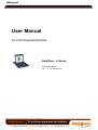
Manual
User Manual
1U LCD Keyboard Drawer
KwikDraw - A Series
- With KVM options
- 15", 17”, 19” screen size
Amplicon.com
IT and Instrumentation for industry
Sales: +44 (0) 1273 570 220 Website: www.amplicon.com Email: [email protected]
Manual
1.1 Important Safeguards
Please read all of these instructions carefully before you use the device. Save this manual for future reference.
What the warranty does not cover
■
Any product, on which the serial number has been defaced, modified or removed.
■
Damage, deterioration or malfunction resulting from:
□
Accident, misuse, neglect, fire, water, lightning, or other acts of nature, unauthorized product modification, or
failure to follow instructions supplied with the product.
□
□
□
□
□
□
□
■
Repair or attempted repair by anyone not authorized by us.
Any damage of the product due to shipment.
Removal or installation of the product.
Causes external to the product, such as electric power fluctuation or failure.
Use of supplies or parts not meeting our specifications.
Normal wear and tear.
Any other causes which does not relate to a product defect.
Removal, installation, and set-up service charges.
P. 1
Amplicon.com
IT and Instrumentation for industry
Sales: +44 (0) 1273 570 220 Website: www.amplicon.com Email: [email protected]
Manual
1.2 Regulatory Notice
Safety Instructions
■
■
Unplug equipment before cleaning. Don’t use liquid or spray detergent; use a moist cloth.
Keep equipment away from excessive humidity and heat. Preferably, keep it in an air-conditioned environment with temperatures not exceeding 40º Celsius (104º Fahrenheit).
■
When installing, place the equipment on a sturdy, level surface to prevent it from accidentally falling and
■
When the drawer is in an open position, do not cover, block or in any way obstruct the gap between it and
causing damage to other equipment or injury to persons nearby.
the power supply. Proper air convection is necessary to keep it from overheating.
■
■
Arrange the equipment’s power cord in such a way that others won’t trip or fall over it.
If you are using a power cord that didn’t ship with the equipment, ensure that it is rated for the voltage
and current labeled on the equipment’s electrical ratings label. The voltage rating on the cord should be
higher than the one listed on the equipment’s ratings label.
■
■
Observe all precautions and warnings attached to the equipment.
If you don’t intend on using the equipment for a long time, disconnect it from the power outlet to prevent
being damaged by transient over-voltage.
■
Keep all liquids away from the equipment to minimize the risk of accidental spillage. Liquid spilled on to
the power supply or on other hardware may cause damage, fire or electrical shock.
■
Only qualified service personnel should open the chassis. Opening it yourself could damage the equipment and invalidate its warranty.
■
If any part of the equipment becomes damaged or stops functioning, have it checked by qualified service
personnel.
Regulatory Notices Federal Communications Commission (FCC)
This equipment has been tested and found to comply with the limits for a Class B digital device, pursuant to Part 15 of the
FCC rules. These limits are designed to provide reasonable protection against harmful interference in a residential
installation.
Any changes or modifications made to this equipment may void the user’s authority to operate this equipment. This
equipment generates, uses, and can radiate radio frequency energy and, if not installed and used in accordance with the
instructions, may cause harmful interference to radio communications.
However, there is no guarantee that interference will not occur in a particular installation. If this equipment does cause
harmful interference to radio or television reception, which can be determined by turning the equipment off and on, the user
is encouraged to try to correct the interference by one or more of the following measures:
■
■
■
Re-position or relocate the receiving antenna.
Increase the separation between the equipment and receiver.
Connect the equipment into an outlet on a85
circuit different from that to which the receiver is connected.
P. 2
Amplicon.com
IT and Instrumentation for industry
Sales: +44 (0) 1273 570 220 Website: www.amplicon.com Email: [email protected]
Manual
1.3 Package Contents
○
1
LCD keyboard drawer x 1 pc
○
2
USB 2-in-1 KVM cable x 1 pc
○
3
Combo 4-in-1 KVM cable x 1 pc
User manual x 1 pc
○
4
Power cord x 1 pc
○
5
Auto switch power adapter ( for external power version) x 1pc
○
6
Mounting bracket x 2 pcs
○
7
○
8
M6*15mm screw x 8 pcs
or
M6 cage nut x 8 pcs
9 Cup washer x 8 pcs
○
P. 3
Amplicon.com
IT and Instrumentation for industry
Sales: +44 (0) 1273 570 220 Website: www.amplicon.com Email: [email protected]
Manual
1.4 Before Installation
■
■
It is very important to locate the LCD Keyboard Drawer in a suitable environment.
The surface for placing and fixing the LCD Keyboard Drawer should be stable and level or mounted into a suitable
cabinet.
■
Make sure the place has good ventilation, is out of direct sunlight, away from sources of excessive dust, dirt, heat, water,
moisture and vibration.
■
Position LCD Keyboard Drawer with respect to related facilities.
1.5 Unpacking
The LCD keyboard drawer comes with the standard parts shown on the package contents. Check and make sure they are included and in
good condition. If anything is missing, or damage, contact the supplier immediately.
P. 4
Amplicon.com
IT and Instrumentation for industry
Sales: +44 (0) 1273 570 220 Website: www.amplicon.com Email: [email protected]
Manual
1.6 Structure Diagram
1
○
Carry handle to release the 2-pt lock
5
○
Membrane switch (KVM option)
2
○
LCD interchangeable module kit
6
○
Micro switch for screen auto power off
3
○
“One Man” Installation Slides
7
○
Keyboard interchangeable module kit
4
○
LCD membrane
8
○
Mouse interchangeable module kit
P. 5
Amplicon.com
IT and Instrumentation for industry
Sales: +44 (0) 1273 570 220 Website: www.amplicon.com Email: [email protected]
Manual
1.7 How to Install "One Man" Installation Slides
Install into rack
■
Attach the left and right mounting bracket to rack 19”
mounting rails.
■
■
Adjust the rear mouting bracket to fit your rack.
M6 screw and cup washer x 6 pcs included.
Caution: Leaving the screws slightly loose, until
you complete the installation in step
■ Pick up the LCD keyboard drawer.
■ Insert the LCD keyboard drawer into the mounting bracket.
■ Pull and hold the left & right black arrow buttons on the rails.
■ Return the LCD keyboard drawer to park position.
P. 6
Amplicon.com
IT and Instrumentation for industry
Sales: +44 (0) 1273 570 220 Website: www.amplicon.com Email: [email protected]
Manual
1.8 How to Install "One Man" Installation Slides
■
Attach front left and right mounting ears of the LCD
keyboard drawer to vertical mounting rails.
■
M6 screw and cup washer x 2 pcs included.
Complete the installation
■
Tighten all 8 pcs of M6 screw to complete the installation.
P. 7
Amplicon.com
IT and Instrumentation for industry
Sales: +44 (0) 1273 570 220 Website: www.amplicon.com Email: [email protected]
Manual
1.9 How to Use the Slides
■
A black arrow release button is located on the
outside of each slide. (shown in Figure 1).
Figure 1.
■
Pull and hold the black arrow button on either side of
the LCD keyboard drawer to unlock. (shown in
Figure 2).
Figure 2.
■
Push the LCD keyboard drawer into the rack. (shown
in Figure 3).
Caution : Keep your fingers away from the slide stop
Figure 3.
P. 8
Amplicon.com
IT and Instrumentation for industry
Sales: +44 (0) 1273 570 220 Website: www.amplicon.com Email: [email protected]
Manual
1.10
How to Use “A” Series LCD Keyboard Drawer
■
Press the carry handle button. Gently pull the
carry handle toward the front of the LCD shown
in Figure 4.
Figure 4. Sliding out the LCD keyboard drawer by pressing the carry
handle button first.
■
Flip up the LCD to a suitable angle shown in Figure 5.
■
Operate the LCD keyboard drawer shown in Figure 6.
Figure 5. Flipping up the LCD to a suitable angle.
Figure 6. Operating the LCD keyboard drawer.
P. 9
Amplicon.com
IT and Instrumentation for industry
Sales: +44 (0) 1273 570 220 Website: www.amplicon.com Email: [email protected]
Manual
1.11 A Series (Single console)
1.12 A Series (Single console)
Caution: The LCD keyboard drawer is hot-pluggable, but components of connected devices, such as the servers
and KVM switch, may not be hot-pluggable. Plugging and unplugging cables while servers and KVM are powered
on may cause irreversible damage to the servers, KVM and LCD keyboard drawer. Before attempting to connect
anything to the LCD keyboard drawer, we suggest turning off the power to all devices before connecting them.
Apply power to connected devices again only after the LCD keyboard is receiving power. The company is not
responsible for damage caused in this way.
P. 10
Amplicon.com
IT and Instrumentation for industry
Sales: +44 (0) 1273 570 220 Website: www.amplicon.com Email: [email protected]
Manual
1.13 A Series (Single console)
1.14 A Series (Single console)
Caution: The LCD keyboard drawer is hot-pluggable, but components of connected devices, such as the servers
and KVM switch, may not be hot-pluggable. Plugging and unplugging cables while servers and KVM are powered
on may cause irreversible damage to the servers, KVM and LCD keyboard drawer. Before attempting to connect
anything to the LCD keyboard drawer, we suggest turning off the power to all devices before connecting them.
Apply power to connected devices again only after the LCD keyboard is receiving power. The company is not
responsible for damage caused in this way.
P. 11
Amplicon.com
IT and Instrumentation for industry
Sales: +44 (0) 1273 570 220 Website: www.amplicon.com Email: [email protected]
Manual
2.1 On-screen Display Operation
15" LCD membrane
17" & 19” LCD membrane
Membrane Switch
Function
Power light
Green = On
Orange = Power saving
Power on / off LCD
Display the OSD menu
Scrolls through menu options and adjusts the displayed control
(To auto adjustment by pressing the button
for 5 seconds)
Exit the OSD screen
Toggle analog, digital & video connection (DVI-D and video options only)
P. 12
Amplicon.com
IT and Instrumentation for industry
Sales: +44 (0) 1273 570 220 Website: www.amplicon.com Email: [email protected]
Manual
2.2 On-screen Menu
OSD Configuration Page
Image:
To enter into the brightness, contrast, colour temp, red, green, and blue
Geometry:
To enter into the auto adjust, H position, V position, phase and clock
Video:
To enter into the colour, tint, sharpness, noise reduction, DCDi and TV Setup
Audio:
To enter into volume, bass, treble, balance, AVL and mute
Misc:
To enter into the language, OSD position, graphic mode, OSD time, ratio, reset and timer
P. 13
Amplicon.com
IT and Instrumentation for industry
Sales: +44 (0) 1273 570 220 Website: www.amplicon.com Email: [email protected]