1
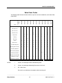
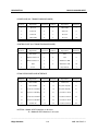
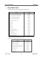
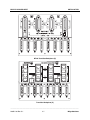
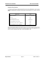
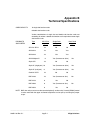
High Density Mk III Plus
Card Nest
Installation Manual
228B1101/C
Milgo Solutions, Inc.
1619 N. Harrison Parkway
P.O. Box 407044
Fort Lauderdale, FL 33340-7044
Internet: http://www.milgo.com
7/96
Third Edition, July, 1996
All logos and product names are trademarks or registered trademarks of their respective companies.
©1999 Milgo Solutions, Inc.
All rights reserved. No part of this work covered by the copyright hereon may be reproduced or copied in any form or by
any means — graphic, electronic, or mechanical, including photocopying, recording, taping, or information and retrieval systems
— without written permission of the publisher. Any software furnished under a license may be used or copied only in accordance
with the terms of such license.
Milgo Solutions, Inc. reserves the right to modify or revise all or part of this document without notice and shall not be
responsible for any loss, cost, or damage, including consequential damage, caused by reliance on these materials.
Printed in U.S.A.
ii
Milgo Solutions
Customer Information Contacts
CORPORATE HEADQUARTERS
Milgo Solutions SA
Parc du Colombier
18 Rue Jules Saulnier
93206 Saint-Denis
Cedex, France
Tel: +331 (0) 49 33 5800
Fax: +331 (0) 49 33 5851
Milgo Solutions, Inc.
1619 North Harrison Parkway
Sunrise, Florida 33323-2802, U.S.A.
Tel: (954)-846-1601/(800)-333-4143
Fax: (954)-846-3935
Internet: http://www.milgo.com
Call Milgo's Corporate Headquarters if you
need the following information:
Press
1
2
3
4
5
6
7
8
For:
Billing or invoice information
Orders, product delivery or availability, and
repairs
Sales
Field service
Training
Employee benefits and information
Corporate quality
Mailing or street addresses
For technical support, please contact your
supplier/distributor with details of the issue.
MILGO SERVICE CONTRACT CUSTOMERS:
For customers with Milgo Service Contracts or
service requirements, contact the following offices:
Milgo Solutions BV
Poortweg 14
2612 PA Delft
The Netherlands
Tel: +31 15 269 82 82
Fax: +31 15 262 18 08
ASIA/PACIFIC
Contact your Milgo affiliate support center. (See
next page for addresses and phone/fax numbers.)
MILGO AFFILIATE SUPPORT CENTERS:
AMERICAS Region
Milgo Solutions, Inc.
1619 North Harrison Parkway
Sunrise, Florida 33323-2802, U.S.A.
Tel: (954)-846-6116/(888)-722-2548
Fax: (954)-846-3692
email: [email protected]
EUROPE/MIDDLE EAST/AFRICA Region
Milgo Solutions, Ltd.
Landata House, Station Road
Hook, Hampshire, RG279JF, England
Tel: +44 (0) 1256 761240
Fax: +44 (0) 1256 382112
email: [email protected]
Internet: www.milgo.com/emea
Bulletin Board Service: +44 1256 766608 (PSTN)
+44 1256 744832/3/4 (ISDN)
AMERICAS
U.S. and U.S. Multinational
Milgo Solutions, Inc.
1619 North Harrison Parkway
Sunrise, Florida 33323-2802
Tel: (954)-846-4569/(800)-366-0126
Fax: (954)-846-1137
EUROPE/MIDDLE EAST/AFRICA
Milgo Solutions, Ltd
Landata House, Station Road
Hook, Hampshire, RG279JF, England
Tel: +44 (0) 1256 763911
Fax: +44 (0) 1256 764717
iii
MILGO AFFILIATE SUPPORT CENTERS:
ASIA/PACIFIC Region
Milgo Solutions (Hong Kong), Ltd.
Sun House 6th Floor
181 Des Voeux Road, Central
Hong Kong
Tel: 852-2815-1886
Fax: 852-2815-2895
Milgo Solutions (Hong Kong) supports:
• China (southern provinces)
• Japan
• Korea
• Hong Kong
• Macau
• Taiwan
Milgo Solutions (Singapore) Pte Ltd.
26 Ayer Rajah Crescent, #04-06
Ayer Rajah Industrial Estate
Singapore 139944
Tel: +65 779 2200
Fax: +65 778 5400
Milgo Solutions (Singapore) supports:
• Brunei
• Indonesia
• Malaysia
• Philippines
• Singapore
• Thailand
• Australia
• New Zealand
• Rest of Indochina
Cambodia
Laos
Myanmar
Vietnam
Milgo Solutions (Beijing), Inc.
Room 20659
Beijing Friendship Hotel
Beijing 100873
Tel: 86-10-6849-8731
Fax: 86-10-6849-8732
Milgo Solutions (Beijing) supports:
• China (northern provinces)
iv
About This Manual
Manual Description
The High Density Mark III Plus Manual provides all the information needed to properly
install and use the card nest. For information on the individual function cards installed in
the card nest, please refer to the appropriate manual for the function card. This manual is
composed of the following chapters and appendices:
Chapter 1 - Description describes the features and capabilities of the High Density
Mark III Plus Card Nest.
Chapter 2 - Installation gives the installation procedure for the card nest and shows
illustrations of backplanes.
Appendix A - International Warnings gives UK statutory warnings and notices
required for UK BABT approvals. It also gives notices that are required by any other
country's approvals regulator.
Appendix B - Technical Specifications provides the card nest specifications and lists the
function cards that may be used in the card nest.
v
About This Manual
vi
MK III PLUS CARD NEST
MK III PLUS HIGH DENSITY CARD NEST
CONTENTS
Page
Chapter 1
Description
1
Introduction
1-1
2
2.1
2.2
2.3
The RS485 Backplane
Function Card Power
Power Supplies
Control and The RS485 Data Bus
2.3.1 RS485 Slot Address
2.3.2 RS485 Unit Address
2.3.3 RS485 Daisy Chaining
1-2
1-3
1-3
1-4
1-6
1-6
1-7
3
3.1
3.2
3.3
3.4
The ALM Transition Backplanes
The Transition Backplane (M)
The Transition Backplane (P)
Control Via The Transition Backplanes (P)
Transition Backplane Customer Interfaces
1-9
1-9
1-10
1-10
1-13
4
Replacement Parts
1-15
Chapter 2
Installation
1
Introduction
2-1
2
2.1
2.2
Connecting The Supplies
Connecting The AC Supply
Connecting The DC Supply
2-1
2-1
2-2
3
Installation
Power Unit Installation
Fitting The Function Cards
2-2
2-3
2-3
4
Additional Information For ALM 3223/3239 & Multiple Card Nests
Control Port Connector
Inter Nest Control Port Cable
Replacement of Transition Backplanes
2-4
2-5
2-5
2-6
Appendix A
International Warnings
A-1
Appendix B
Technical Specifications
B-1
5
____________________________________________________________________________________
228B 1101 Rev C.1
vii
Milgo Solutions
MK III PLUS CARD NEST
Sales Order Codes
MN8571
8
MN8572
8
PSU 230 volt a.c.
MN8573
8
MN8574
8
MN8575
MN8569
8
MN8576
MN8568
8
MN8570
MN8567
Nest
MN8566
Items
Sales Order
Codes
The following table indicates the items which are part of, and are included with, each Sales Order
Code (SOC):
8
8
8
8
8
8
8
8
8
8
8
8
8
8
8
8
PSU 115 volt a.c.
8
PSU 48 volt d.c.
Cable, PSU
8
UK Plug
8
8
8
8
8
8
8
8
8
8
8
8
8
Euro Plug
8
Manual
PSU Screws ±
8
8
8
8
8
8
8
8
8
8
8
8
8
8
8
8
8
8
8
8
PSU Mounting Plate
8
8
8
8
8
8
8
8
8
8
8
Mounting Plate Screws ²
8
8
8
8
8
8
8
8
8
8
8
88
RJ45 Busy Out BP ³
88
RJ45 Non Busy Out BP ³
88
BT226 Busy Out BP ³
88
88
BT226 Non Busy Out BP ³
88
RS485 BP ³ Jumper
8
8
8
8
8
8
8
8
8
8
8
RS485 BP ³ Terminator
88
88
88
88
88
88
88
88
88
88
88
NOTES
±
Screws, for attaching the PSU to the Mounting Plate.
²
Screws, for attaching the Mounting Plate to the 19 inch rack.
³
BP = Back Plane
Busy Out is an indication to the network and the incoming call.
____________________________________________________________________________________
Milgo Solutions
viii
228B 1101 Rev C.1
MK III PLUS CARD NEST
____________________________________________________________________________________
228B 1101 Rev C.1
ix
Milgo Solutions
MK III PLUS CARD NEST
____________________________________________________________________________________
Milgo Solutions
x
228B 1101 Rev C.1
CHAPTER 1
DESCRIPTION
1
INTRODUCTION
The Milgo Solutions Mk III Plus High Density Card nest is designed to fit a standard 19 inch rack
and to accommodate a maximum of sixteen Milgo Solutions single function card devices or eight
double width (50 mm) function cards. A mixture of single and double width function cards may be
fitted depending on physical limitations.
The function cards slide into the card nest on card guides, and connect into backplane edge
connectors. The lower backplane is known as the RS485 Backplane and this supplies power to all
function cards. If designed for it, function cards can also make use of the built-in unit/slot address
system, the RS485 data bus or the open collector bus which are all carried on the RS485
Backplane.
The RS485 bus can also facilitate the connection of CMS 400 nodes to a CMS 400 network. For
CMS 400 control, a master node in the card nest is connected to the network and control to the
other slave CMS 400 nodes in the card nest is via the RS485 bus and the master node. The card
nest will support up to 1 master node and fifteen slave nodes (if the units are 25 mm units) or 2
master nodes and seven slave nodes (if the units are 25 mm units). The 16 slot backplane is
converted to an 8 slot backplane by removal of the RS485 jumper. If 50 mm units are in use, the
card nest will accommodate half of these numbers. Mixtures of high density cards (25 mm and 50
mm) and types of unit are also possible.
The High Density Mk III Plus card nest is available for use with either a.c. or d.c. power supplies.
When using the RS485 Backplane for power and/or RS485 control purposes, the Alpha IV, DAP
4100 and DAP 4500 cards will utilise PSTN, Leased Line, DTE and Control ports which are
mounted directly on the individual function cards. These high density cards each have a 36 way
edge connector which mate directly with a backplane connector in the High Density Mk III Plus
Card Nest. If RS485 control is not required, these cards are also compatible with earlier Mk III
Card Nests.
____________________________________________________________________________________
228B 1101 Rev C.1
1-1
Milgo Solutions
DESCRIPTION
2
MK III PLUS CARD NEST
THE RS485 BACKPLANE
The purpose of the RS485 Backplane is to carry power to all function cards and to connect the
nest address (for control purposes) and the RS485 bus to all function cards. This is achieved via
the 36 way edge connectors.
TABLE 1
36 Way Edge Connectors
NOTES
Pin
Signal Name
Pin
Signal Name
1
Protective Ground
19
B1
2
Protective Ground
20
B0
3
RS485N
21
12 VAC or 18 VDC
4
RS485P
22
12 VAC or 18 VDC
5
DO NOT USE
23
+12 VAC or +18 VDC
6
DO NOT USE
24
+12 VAC or +18 VDC
7
Spare
25
9 VAC or 12 VDC
8
Spare
26
9 VAC or 12 VDC
9
DO NOT USE
27
+9 VAC or +12 VDC
10
DO NOT USE
28
+9 VAC or +12 VDC
11
RS485E
29
14 VAC or 18 VDC
12
X0
30
14 VAC or 18 VDC
13
B7
31
+14 VAC or +18 VDC
14
B6
32
+14 VAC or +18 VDC
15
B5
33
0V
16
B4
34
0V
17
B3
35
Protective Ground
18
B2
36
Protective ground
The pins marked DO NOT USE have been purposely omitted from the sockets.
This is to ensure that equipment presently designated to use the older High
Density Mark II/III card nests remains compatible with the High Density Mark III
Plus card nest.
____________________________________________________________________________________
Milgo Solutions
1-2
228B 1101 Rev C.1
MK III PLUS CARD NEST
DESCRIPTION
The sixteen card slots are numbered 1 to 16 to correspond with the addresses
carried by the slots.
2.1
Function Card Power
The RS485 Backplane connects the power supplies (Table 1, pins 21 to 32) to the function cards:
*
The a.c. supplies (pins 21 to 32) are the low power a.c. supplies obtained from the a.c.
power unit PSU 301 (115 volts a.c. or 230 volts a.c. version)
*
The d.c. supplies (pins 21 to 32) are the d.c. supplies obtained from the d.c. power unit.
Generally, all cards designed for installation in the Milgo Solutions Mk III High Density Card Nests
should work with either (a.c. or d.c.) type of supply. The individual function card bridge rectifiers
will only allow a supply of the correct polarity through to the function card regulators.
2.2
Power Supplies
The card nest may obtain power for the function cards from either an a.c. power unit or a d.c.
power unit:
*
*
The a.c. power unit provides the a.c. supplies listed in Table 1 and complete isolation to
the mains supply. The a.c. power unit may be either 115 volts or 230 volts a.c. The
following power is available from the a.c. power unit:
Supply
PSU Rating
Max Single Slot Current
Max Single
9-0-9
8•3 Amps (150 VA)
518 mA
9•32 VA
14 - 12 - 0 - 12 - 14
5•3 Amps (150 VA)
331 mA
9•27 VA
The d.c. power unit is a proprietary d.c. to d.c. converter, which works on the switched
mode principle. It provides the d.c. supplies listed in Table 1. The following power is
available from the d.c. power unit:
Supply
PSU Rating
Max Single Slot Current
Max Single
+12 volts
8•3 Amps
518 mA
6•22 Watts
12 volts
3 Amps
187 mA
2•24 Watts
+18 volts
4•5 Amps
281 mA
5•06 Watts
18 volts
4•5 Amps
281 mA
5•06 Watts
____________________________________________________________________________________
228B 1101 Rev C.1
1-3
Milgo Solutions
DESCRIPTION
MK III PLUS CARD NEST
Power from the Power Supply Units is supplied to the High Density Mk III Plus card nest via a 2 metre
long power cable. The power cable connects to the RS485 Backplane via a twelve way socket P1, which
has the following pin assignment:
2.3
Pin Number
PS 301 (115 or 230) Power Unit
DC Power Unit
1
12 volts a.c.
+18 volts d.c.
2
12 volts a.c.
18 volts d.c.
3
Not used
Not used
4
9 volts a.c.
12 volts d.c.
5
Not used
Not used
6
Not used
Not used
7
9 volts a.c.
+12 volts d.c.
8
9 volts centre tap
0 volts (12 volts)
9
Not used
Not used
10
14 volts a.c.
+18 volts d.c.
11
14 volts a.c.
18 volts d.c.
12
14 volts centre tap
0 volts (18 volts)
Control and The RS485 Data Bus
NOTE ALM 3223 and ALM 3239 modems cannot be controlled using this RS485 configuration.
Please refer to section 3 if you are using these products.
This form of RS485 control uses a single point control port connection (to one function card) which
allows control of other function cards in this Mk III Plus cardnest and any daisy chained cardnests.
For this form of control, the cardnest must contain either Alpha IV or ALM Multiport IV modems, or
DAP 4000 series terminal adaptors. In this context, terminal adaptors must not be mixed with
modems.
Terminal adaptors and modems can only use RS485 control (in the same card nest) if the RS485
jumper is removed and each half of the card nest is provided with its own single point of control.
Modems and terminal adaptors should be installed separately in each half of the cardnest.
The RS485 bus provides industry standard communication to the function cards over a two wire
circuit which operates in half duplex mode. A Control Port/RS485 Bus control may run in one of
two modes:
*
Using a dumb terminal, or a PC running terminal emulation software, and control port
operation for the cards. This is Terminal Mode.
____________________________________________________________________________________
Milgo Solutions
1-4
228B 1101 Rev C.1
MK III PLUS CARD NEST
*
DESCRIPTION
Using a CMS 400 network management terminal via a T7 port on a network and an EDM.
This is Network Mode.
RS485 bus daisy chaining is used typically where control is from a terminal. If CMS 400 network
control is in use, to optimise CMS 400 performance, the bus on each High Density Mk III Plus
card nest is split into two (by removing the RS485 bus jumper connector) and each group of eight
cards is separately addressed.
For Terminal Mode, each function card has an individual address which is based on its slot
number in the card nest. In any High Density Mk III Plus card nest, the function card which is
connected to the Control terminal or the CMS 400 network must be configured as a Master card;
the remainder of the cards being controlled through this card must be configured as slave cards
(this is necessary because of the half duplex nature of the bus). The Master function card can be
placed in any slot in the card nest. For Network Mode, each card uses a CMS 400 node identity in
addition to being either a Master or a Slave card.
For Terminal Control purposes, function cards in the nest which are to be controlled require an
address. Non CMS 400 compatible units can make use of the hard wired address system. This is
made up of a slot address and a unit address. Both addresses are read, combined together and
used to identify the card to the controller, see sections 2.3.1 and 2.3.2.
The pin assignment of the RJ45 control port connector is:
Pin Number
Signal Name
1
485P
2
485E
8
485N
For control purposes, it is possible to configure the RS485 Backplane as one 16 slot unit or two 8
slot units. This is accomplished by either fitting, or not fitting, the jumper connector between the
two central RJ45 control ports. If the RS485 Backplane is split into two control sections, these
sections can also be controlled independently by different controllers connected to the RJ45
control ports. In both 8 slot and 16 slot configurations, the controller may be connected to either of
the two control ports. A RS485 bus terminator must be fitted to the RS485 port at the bus end and
(in the 16 slot configuration) the control port jumper fitted between the two central RS485 ports.
NOTE The RS485 Jumper is a short "one to one", connector which is not suitable for daisy
chaining.
The following illustration shows the 'as shipped' RS485 configuration where control is connected
to any function card. The second and third RS485 ports are linked with the RS485 jumper and the
first and last RS485 ports contains the terminator plugs. RS485 terminator plugs (part number
27R497) are shipped with each High Density Mk III Plus card nest.
____________________________________________________________________________________
228B 1101 Rev C.1
1-5
Milgo Solutions
DESCRIPTION
MK III PLUS CARD NEST
The RS485 Backplane
2.3.1
RS485 Slot Address
All card slots in the card nest have (for the purposes of control) a hard wired address (see Table
1) using signals B3 to B0 on pins 17 to 20. B0 (pin 20) is the least significant bit (LSB) and B3 (pin
17) the most significant bit (MSB). The four bit signal lines, which are pulled high by resistors on
the cards, give the following card addresses:
Card Slot Address
Card Slot Address
1
0
5
2
1
6
3
2
4
3
4
Card Slot Address
Card Slot Address
9
8
13
12
5
10
9
14
13
7
6
11
10
15
14
8
7
12
11
16
15
The slot address is used in conjunction with the unit address primarily for control from an ANSI
compatible terminal. The slot address only is used in CMS 400 control together with the node's
CMS 400 node identity.
2.3.2
RS485 Unit Address
A unit address (for the purposes of control) can be set up (see Table 1) using signals B7 to B4 on
pins 13 to 16. B4 (pin 16) is the least significant bit (LSB) and B7 (pin 13) the most significant bit
(MSB). The four-bit signal lines, which are pulled high by resistors on the cards, are connected to
ground by operation of the DIL switch (S1) on the RS485 Backplane.
NOTES
Some products do not support the use of the full range of four bit addresses
which are available. Check with your product documentation or support desk for
information in this instance.
____________________________________________________________________________________
Milgo Solutions
1-6
228B 1101 Rev C.1
MK III PLUS CARD NEST
DESCRIPTION
The DIL switch (S1) reads left to right when viewed from the rear and switch position UP = ON.
The following table lists possible RS485 backplane unit addresses:
S1.1
S1.2
S1.3
S1.4
Address
(Decimal)
On
On
On
On
1
Off
On
On
On
2
On
Off
On
On
3
Off
Off
On
On
4
On
On
Off
On
5
Off
On
Off
On
6
On
Off
Off
On
7
Off
Off
Off
On
8
On
On
On
Off
9
Off
On
On
Off
10
On
Off
On
Off
11
Off
Off
On
Off
12
On
On
Off
Off
13
Off
On
Off
Off
14
On
Off
Off
Off
15
Off
Off
Off
Off
16
The unit address, in conjunction with the slot address, is used primarily for control from a terminal.
The unit address may be set in addition to any CMS 400 node addresses which are set.
2.3.3
RS485 Daisy Chaining
Up to five RS485 Backplanes (or 10 half backplanes) can be daisy chained together for the
purposes of control from a terminal. This limitation is built into the software of function cards and
also takes into account the physical impracticalities of a bus of this length. The RS485 Backplanes
(or half backplanes) may be connected together over the RS485 data bus in any order so long as
each backplane has a different unit address and terminator plugs are connected into the spare
RS485 ports on the first and last RS485 Backplanes in the chain. A possible configuration is
shown in the following illustration:
____________________________________________________________________________________
228B 1101 Rev C.1
1-7
Milgo Solutions
DESCRIPTION
MK III PLUS CARD NEST
Control
Port
RS485 Terminator
RS485
Jumper
Connectors
CONTROL
Control can be from a terminal or an
EDM connected to a T7 port on a
CMS 400 network.
RS485
Inter Unit
Connectors
RS485 Terminator
Power Supply Units
A Typical Daisy Chained High Density Mk III Plus Installation
NOTE Daisy chaining the RS485 bus is not recommended for CMS 400 applications. For CMS
400, the use of more Master units controlling smaller numbers of slave units will help
maintain network response times.
____________________________________________________________________________________
Milgo Solutions
1-8
228B 1101 Rev C.1
MK III PLUS CARD NEST
3
DESCRIPTION
THE ALM TRANSITION BACKPLANES
If ALM Transition Backplanes are fitted, only ALM 3223 or ALM 3239 units can be fitted in the Mk
III Plus card nest. It is not physically possible to fit other units.
The ALM Transition Backplanes are fitted above the RS485 Backplane and carry customer
interface connectors for DTE, PSTN/Leased Line and Control/Diagnostics. Optionally, a Busy Out
signal is available to the network. Backplanes are for use primarily with the ALM 3xxx modem
range (a 25 mm wide unit) although their use with other units is not precluded. Customer
interfaces mounted on Transition Backplanes mate with edge connectors on the upper part of the
function cards. The following Transition Backplane versions, which are all 8 slot, are available:
*
The Backplane (M) having 8 x DTE (25 way D type socket), 8 x PSTN (RJ45), 8 x Leased
Line (RJ45) and 8 x Control ports (RJ45).
*
The Backplane (P) having 8 x PSTN (RJ45), 8 x Leased Line (RJ45) and 2 x Control
ports to allow daisy chaining. Control signals are routed to all other cards in the card nest
via the open collector bus on the RS485 Backplane. For control purposes, up to four other
card nests (using the this type of Transition Backplane) can be daisy chained together.
*
The BT226 Backplane having 4 x PSTN/Leased Line (24 way BT226) connectors and 2 x
Control ports to allow daisy chaining. Control signals are routed to all other cards in the
card nest via the open collector bus on the RS485 Backplane. For control purposes, up to
four other card nests (using this type of Transition backplane) can be daisy chained
together. (This backplane is a limited edition).
The transition backplanes all span eight slots of the High Density MK III Plus card nest. This
requires that two transition backplanes are fitted for a full sixteen slot unit. All Transition
Backplanes facilitate the changing of function cards from the front of the card nest without the
need to individually handle the interface connectors.
All of the Transition Backplane types are capable of on-site replacement in-order to satisfy
changing customer interface requirements. Backplanes must only be changed by trained
telecommunication technicians.
3.1
The Transition Backplane (M)
The Backplane (M) is a robust construction which carries the customer interface connectors for
eight single function cards. This transition backplane provides the following customer interface
connectors for each function card: 25 way D type sockets for the DTE connectors, RJ45
connectors for the PSTN, Leased Line and Control connections. This backplane does not support
the Busy Out feature.
The Backplane (M) pin assignments (of the customer interfaces) are listed after the description of
all three types of transition backplane.
____________________________________________________________________________________
228B 1101 Rev C.1
1-9
Milgo Solutions
DESCRIPTION
3.2
MK III PLUS CARD NEST
The Transition Backplane (P)
Their are two versions of the Transition Backplane (P), for PCB. The two versions differ mainly in
their customer interface arrangements, as follows:
*
The Backplane (P) carries eight 25 way D type sockets for the DTE connectors, eight
RJ45 connectors for the PSTN, eight RJ45 connectors for the Leased Line and two
Control connectors. The control connectors allow one actual control connection and one
daisy chain connection to the transition backplane and both connectors are identically
wired. The Backplane (P) incorporates the Busy Out feature and has straps to select the
line resistance for this feature.
*
The BT226 Backplane (P) carries eight 25 way D type sockets for the DTE connectors,
four 24 way BT226 connectors for both the PSTN and Leased Line interfaces for two
function cards and two Control connectors. The control connectors allow one actual
control connection and one daisy chain connection to the transition backplane and both
connectors are identically wired. The BT226 Backplane is available with or without the
Busy Out feature. If Busy Out is fitted, the backplane incorporates straps to select the line
resistance for this feature. This backplane is not on general release.
The Busy Out feature consists of circuitry fitted to all slots in the PCB Based Transition
Backplanes. It connects a selected impedance across the PSTN line when the particular card is
either powered down, withdrawn (from the High Density Mk III Plus card nest) or when the card is
unable to accept a call, i.e. DTR is Low etc. The loss of power to the card or the action of
withdrawing it from the nest de-energises a solid state relay to connect the selected impedance
across the PSTN line. Straps A to H (one for each modem card) select this impedance:
Busy Out Impedance:
Strap Position 1
Strap Position 2
Strap Position 3
33 kΩ
270 Ω
0Ω
The Busy Out feature is a factory build and ordering option. The Zero Ohm option is not permitted
under the current British Standards and is not available at the present time. Busy Out can be
disabled by the removal of the strap or the line impedance resistors. Non-Busy Out transition
backplanes are available to suit network requirements. The Busy Out straps should not normally
be changed. Should the need to changed these straps arise, the services of a Public
Telecommunications Engineer must be obtained. Alternatively, contact your local Milgo Solutions
office to arrange for a customer service engineer.
3.3
Control Via The Transition Backplanes (P)
If the function cards are designed for remote control (using the open collector bus on the RS485
Backplane) control port connection and daisy chaining to another card nest is implemented on the
transition backplane. Since the open collector bus extends for the full width (sixteen card slots) of
the card nest, it is only necessary to connect the controller to one control port on one of the
transition backplanes. No control daisy chaining is necessary if function cards in this one card
nest only are to be controlled.
____________________________________________________________________________________
Milgo Solutions
1-10
228B 1101 Rev C.1
MK III PLUS CARD NEST
DESCRIPTION
Up to five High Density Mk III Plus card nests (using their respective open collector busses) may
be daisy chained together using the control ports on the PCB Based Transition Backplanes. The
requirements for remote control using the transition backplanes are:
*
The control and daisy chain connectors are connected to transition backplane connectors
in a card nest. If only one transition backplane is in use, it must be in a position
corresponding to function cards 1 to 8.
*
If control is required for one card nest only, a function card must be installed in a position
which has an RJ45 control port. This will be slot 1, 8, 9 or 16 and for control purposes
only one of these slots need be filled. This function card will connect the control port, via
the transition backplane, to the bus on the RS485 Backplane and to all other function
cards fitted in this card nest.
*
If a daisy chain connection to another High Density Mk III Plus card nest is required, a
function card must also be installed in line with the second RJ45 control port connector on
the transition backplane on which the control port is being used, i.e. slot 8 for slot 1, slot
16 for slot 9 or vice versa. This function card will connect the bus on the RS485
Backplane, to the daisy chain control port on the transition backplane and the next card
nest down the line.
If designed for it, function cards using remote control via a transition backplane control port, can
make use of the Slot Address and Unit Address features described earlier in this chapter in
sections 2.3, 2.3.1 and 2.3.2.
____________________________________________________________________________________
228B 1101 Rev C.1
1-11
Milgo Solutions
DESCRIPTION
MK III PLUS CARD NEST
Control Via The PCB Backplanes
NOTES ±
The connector from the terminal to the control port on the first nest must go to a
backplane control port which is associated with a card. Port B and Card Slot 1 are
recommended.
²
The inter nest control port cable must be connected from another control port (in
the same cardnest having a card associated with it) to a control port on the last
cardnest (which is also associated with a card). Port A / Card Slot 8 to Port B /
Card Slot 1 are recommended here.
Wiring information for the inter nest link cable is given in Chapter 2.
____________________________________________________________________________________
Milgo Solutions
1-12
228B 1101 Rev C.1
MK III PLUS CARD NEST
DESCRIPTION
For EMC reasons, cards should be installed starting at slot 1 and leaving any
empty slots at the right hand end of the cardnest (when viewed from the front).
3.4
Transition Backplane Customer Interfaces
DTE CONNECTORS (ALL TRANSITION BACKPLANES)
These are 25 way D type sockets with a pin assignment as follows:
Pin No.
V.24 Signal
Pin No.
V.24 Signal
1
Protective ground
15
TxC
2
TxD
16
Secondary RxD
3
RxD
17
RxC
4
RTS
18
Local Analogue Loop
5
CTS
19
Secondary RTS
6
DSR
20
DTR
7
Signal Ground
21
Remote Digital Loop
8
DCD
22
RI
9
Positive Test Volts
23
Speed Select
10
Negative Test Volts
24
ExTC
14
Secondary TxD
25
TMI
NOTE The above table shows a common 25 way D type connector DTE pin assignment. The
actual pin assignment is product specific and may be different to the above list.
PSTN (ALL TRANSITION BACKPLANES)
RJ45 Pin
Signal Name
Card Pin No.
RJ45 Pin
Signal Name
Card Pin No.
1
Tel TIP
1
5
Line TIP
5
2
Tel RING
4
6
MIC (US Only)
8
3
MI (US Only)
3
7
Program Resistor
7
4
Line RING
6
8
Program Resistor
10
____________________________________________________________________________________
228B 1101 Rev C.1
1-13
Milgo Solutions
DESCRIPTION
MK III PLUS CARD NEST
LEASED LINE (ALL TRANSITION BACKPLANES)
RJ45 Pin
Signal Name
Card Pin No.
RJ45 Pin
Signal Name
Card Pin No.
1
Not used
1
5
4 Wire RING
5
2
4 Wire TIP
4
6
4 Wire TIP
8
3
2 Wire TIP
3
7
Not Used
7
4
2 Wire RING
6
8
Not Used
10
CONTROL PORT (ALL TRANSITION BACKPLANES)
RJ45 Pin
Signal Name
Card Pin No.
RJ45 Pin
Signal Name
Card Pin No.
Busy Anode
2
5
RxD
5
1
DSR/Constellation X
1
6
TxD
8
2
DCD/Constellation Y
4
7
CTS/Chassis RxD
7
3
DTR
3
8
RTS/Chassis TxD
10
4
0 volts
6
Busy Cathode
9
BT226 PSTN/LEASED LINE INTERFACE
BT226 Pin
Signal Name
Card Pin No.
BT226 Pin
Signal Name
Card Pin No.
1
PSTN A RING
6
14
PSTN B TIP
5
2
PSTN B RING
6
17
Busy Wire A (Earth)
n.c.
9
Leased Line A Tx RING
6
18
Busy Wire B (Earth)
n.c.
10
Leased Line A Rx RING
5
21
Leased Line A Tx TIP
3
11
Leased Line B Tx RING
6
22
Leased Line A Rx TIP
8, 4
12
Leased Line B Rx RING
5
23
Leased Line B Tx TIP
3
13
PSTN A TIP
13
24
Leased Line B Rx TIP
8, 4
NOTES A = Modem A PSTN Interface, in all cases.
B = Modem B PSTN Interface, in all cases.
____________________________________________________________________________________
Milgo Solutions
1-14
228B 1101 Rev C.1
MK III PLUS CARD NEST
4
DESCRIPTION
REPLACEMENT PARTS
The following items are available using the order numbers given here:
Assembly
Part Number
Mk III Plus Card Nest with, 230 VAC PSU (UK)
MN 8567
Mk III Plus Card Nest with, 230 VAC PSU (Euro)
MN 8568
Mk III Plus Card Nest with 115 VAC PSU
MN 8569
Mk III Plus Card Nest with 48 VDC PSU
MN 8570
Mk III Plus Card Nest with no PSU
MN 8566
240 VAC PSU
MN 1391
115 VAC PSU
MN 3934
48 VDC PSU
MN 7500
Backplane (M)
MN 7747
Backplane (P)
MN 7748
BT226 Backplane (Busy Out)
MN 7497
BT226 Backplane (Non - Busy out)
MN 7746
1 U Ventilation Panel
CN 1593
1 inch Blanking Panel (Plastic)
MN 7946
1 inch Blanking Panel (Metal)
MN 1396
The following power supply module items are available:
Assembly
Part Number
Transformer, mains, 300 VA
1R208 (230 V)
Transformer, mains, 300 VA
1R151 (115 V)
Thermal Trip Circuit Breaker, 25 A (230 V)
15R114-11
Thermal Trip Circuit Breaker, 50 A (115 V)
15R114-12
Connector plug, 12 way
27R127-12
Contact socket
27R127-27
Low voltage cables:
413K 2215-010 (1 metre)
____________________________________________________________________________________
228B 1101 Rev C.1
1-15
Milgo Solutions
DESCRIPTION
MK III PLUS CARD NEST
413K 2215-0xy
(for xy metre length)
Power Supply Tray
4413A 424A
Power Supply Mounting Plate, 4 U
MN 8455
____________________________________________________________________________________
Milgo Solutions
1-16
228B 1101 Rev C.1
CHAPTER 2
INSTALLATION
1
INTRODUCTION
This chapter gives procedures for installing a High Density Mk III Plus card nest and for changing
a transition backplane.
2
CONNECTING THE SUPPLIES
The High Density Mk III Plus card nest supplies power to the function cards from one of the
following power units:
*
A 230 volt, mains powered unit.
*
A 115 volt, mains powered unit.
*
A 48 volt, d.c. to d.c. converter.
These power units all supply power via an identically wired connector to the power connector on
the RS485 Backplane. The power connector pin assignment is given in Chapter 1.
2.1
Connecting The AC Supply
High Density Mk III Plus card nest a.c. power units, for use in the UK, are supplied with a 13 amp
mains connector.
The wires in the mains lead on the a.c. power units are colour coded in as follows:
EARTH
Green/yellow
NEUTRAL
Blue
LIVE
Brown
If for any reason the moulded on mains plug has to be replaced by a new mains plug, the
terminals shall be connected as follows:
The wire which is coloured GREEN and YELLOW must be connected to the terminal in
the plug which is marked by the letter E, or by the safety earth symbol, or coloured green
and yellow.
____________________________________________________________________________________
228B 1101 Rev C.1
2-1
Milgo Solutions
INSTALLATION
MK III PLUS CARD NEST
The wire which is coloured BLUE must be connected to the terminal which is marked with
a letter N or coloured black.
The wire which is coloured BROWN must be connected to the terminal which is marked
with the letter L or coloured red.
2.2
Connecting The DC Supply
The d.c. to d.c. converter is powered from an exchange type (nominal 48 volt) supply. The
converter must be connected to the d.c. supply using cable suitable for the 10 ampere drain and
which will give a converter terminal voltage in the range 60 volts to 40 volts.
Connect the building d.c. supply to the converter d.c. input connector as follows:
48 VDC
Minus d.c. supply
Signal Ground
Plus (ground) d.c. supply
Protective Ground
Building earth system
The converter also has an earth terminal. This must be connected to the earth terminal on the
High Density Mk III Plus card nest before any power is applied.
3
INSTALLATION
If a card nest is to be installed in an equipment rack with equipment above and/or below it, a gap
of at least 1U must be left. The use of the optional 1 U ventilation panel is recommended. This
panel is mounted below the card nest and will increase the airflow through the card nest.
There is also an option to provide forced air cooling for high ambient temperatures. This is
achieved by installing a Fan Tray (complete with fans) below the Mk III Plus Card Nest.
Proceed as follows:
1.
Inspect the Card Nest, power unit and cables for signs of damage.
2.
Ensure that the power unit is compatible with the intended local supply (a.c. or d.c.).
3.
With the Card nest empty, position it as required in the equipment rack and secure in
place using four suitable screws.
4.
a)
Connect an Earth Lead between the stud on the PSU Case and the Card nest.
b)
Ensure that the Card Nest has a good earth to the cabinet which is being used.
c)
Check that the cabinet earth is connected to a good clean earth point.
____________________________________________________________________________________
Milgo Solutions
2-2
228B 1101 Rev C.1
MK III PLUS CARD NEST
INSTALLATION
Power Unit Installation
Before applying any power, install the power unit as follows:
1.
Mount the a.c. PSU 301 or the d.c. to d.c. converter onto the 19 inch cabinet mounting
plate provided and secure using the four screws, also provided.
2.
Secure the mounting plate (with the power unit) behind the card nest or in any other
suitable location in the equipment rack.
3.
Connect the cable from the power unit to the rear panel power connector P1.
Fitting The Function Cards
1.
Attach all DTE, PSTN, ISDN and control connections to the appropriate connectors on the
transition backplanes (if fitted) in accordance with local regulations. Ensure that the
connector retaining mechanisms are used and are secure.
2.
After the appropriate Function Card hardware configuration has been carried, insert the
Function Cards as follows:
•
Insert the first Function Card in slot 1. This is the extreme Left Hand (LH) card
slot when the card nest is viewed from the front.
•
Insert the remaining Function Cards working from slot 2, in a left to right direction
(when viewed from the front). Function Cards should be fitted close together
leaving no card slots empty.
•
When all Function Cards are in place, fit the blank metal card (which is supplied
with the Mark III Plus Card Nest) in the next card slot position.
•
Leave any empty slots at the Right Hand (RH) end of the card nest, when viewed
from the front.
NOTE Function Cards must be fitted in this way in order that the Mark III Plus Card Nest
complies with the requirements of the CE mark directives (see Appendix A).
3.
Secure all front panels with their Dzus fasteners.
4.
Fit blanking plates over any other unused slot positions.
5.
With the power switched OFF, insert the a.c. mains plug into a power outlet. For all types
of power unit, ensure that the power cable is not under strain before applying power to the
power unit.
6.
Switch the power switch to ON.
7.
Check that the Function Card power indicators are lit.
____________________________________________________________________________________
228B 1101 Rev C.1
2-3
Milgo Solutions
INSTALLATION
MK III PLUS CARD NEST
NOTE If this installation is in the United States of America, please refer to the supplementary
instructions given in Appendix A, under the main heading of National Warnings.
4
ADDITIONAL INFORMATION FOR ALM 3223/3239
& MULTIPLE CARD NESTS
Install individual card nests in accordance with the instructions earlier in this chapter. The
following notes are supplied for guidance:
•
Ensure that each Mk III Plus card nest has a different RS485 unit number.
•
Ensure that you are aware of the card configuration of your card nests before attempting
to run the nest. If necessary make a note for each card nest showing its cards, the card
IDs and the proposed connections etc.
•
For single control port operation, although you could use any of the control ports on the
upper backplanes for the single point control port connection, to keep things simple it is
best to connect to Port A and use the card in slot 1 as the master card. (You could have
used Port B and with the card in slot 8 as the master card, or even the other upper
backplane if fitted).
Keeping things simple, connect Port B on the first backplane to Port A on the first
backplane in the next card nest.
For single point control port operation it is recommended that no more than five Mk III
Plus card nests are connected together in a single point control system.
•
If you are eventually going to use CMS 400 (in any configuration) ensure that each
individual function card has its own unique CMS 400 identity. This must be done from the
terminal via the control port before switching to CMS 400.
•
If using CMS 400 it is recommended that individual card nests are connected to different
EDM channels. Daisy chaining for CMS 400 operation would result in slow management
traffic although the speed of data traffic would not be affected. In each Mk III Plus card
nest, connect Port A on the first upper backplane to an EDM channel.
____________________________________________________________________________________
Milgo Solutions
2-4
228B 1101 Rev C.1
MK III PLUS CARD NEST
INSTALLATION
Control Port Connector
This connector may either be a 25 way D type to RJ45 or a 9 way D type to RJ45. At the D type
connector end, DTR is linked to DSR and RTS is linked to CTS.
Control Port Connector
Terminal
25 way D Type
Terminal
9 way D Type
Back Plane Control Port
RJ45
Signal
Pin Number
Signal
Pin Number
Signal
Signal Ground
RxD
TxD
7
3
2
Signal Ground
RxD
TxD
5
2
3
0 volts
RxD
TxD
DTR/DSR
RTS/CTS
20//6
4/5
DTR/DSR
RTS/CTS
4/6
7/8
Pin number
4
5
6
Link at terminal end
Link at terminal end
Inter Nest Control Port Cable
The purpose of this cable is to daisy chain the nests together using the control port connectors on
each nest, see table and diagram below:
Inter Nest Control Port Connector
Upstream Nest
(A End)
Downstream Nest
(B End)
Signal
Pin Number
Signal
Pin Number
RxD
TxD
0 volts
7
8
4
TxD
RxD
0 volts
6
5
4
Inter Nest Cabling
____________________________________________________________________________________
228B 1101 Rev C.1
2-5
Milgo Solutions
INSTALLATION
5
MK III PLUS CARD NEST
REPLACEMENT OF TRANSITION BACKPLANES
It is possible for the Transition Backplanes to be replaced. If the Transition Backplanes are to be
replaced, the services of a trained telecommunications technician must be obtained. Alternatively,
contact Milgo Solutions Ltd at the address given at the front of this manual to arrange for a
customer service visit.
Full installation procedures are supplied with replacement transition backplanes.
CAUTION
This equipment uses Posidriv crosshead screws. Use only Posidriv screwdrivers
of the correct size.
If an incorrect type of screwdriver is used, damage to the screw heads will result.
The correct sizes of Posidriv screwdrivers for some common metric sized screws
are as follows:
Screws
Posidriv Screwdriver
M2 & M3
M4
M5 & M6
0 Pt
1 Pt
2 Pt
Transition Backplane (M)
____________________________________________________________________________________
Milgo Solutions
2-6
228B 1101 Rev C.1
MK III PLUS CARD NEST
INSTALLATION
BT226 Transition Backplane (P)
Transition Backplane (P)
____________________________________________________________________________________
228B 1101 Rev C.1
2-7
Milgo Solutions
Appendix A
International Warnings
UNITED KINGDOM
WARNINGS
Warnings are concerned with danger to personnel.
HIGH VOLTAGES
This unit uses the domestic a.c. supply. Under no circumstances is it to be
operated with the covers removed.
DANGEROUS
SUBSTANCES
Semiconductor devices contain dangerous substances, such as
beryllium and arsenic. Electronic devices must not be opened. If they
become damaged, they must only be handled using protective gloves.
If the substances, inside electronic devices, come into contact with
broken skin or wounds, hospital care must be sought immediately.
Electronic components must be disposed of as hazardous toxic waste
and must not be incinerated.
GENERAL
At all times working practices must be in accordance with the Health and
Safety at Work Act, and the Control of Substances Hazardous to Health
(COSHH) regulations.
CAUTIONS
Cautions are concerned with damage to equipment or systems.
CMOS DEVICES
The electronic components in this unit use Complimentary Metal Oxide
Semiconductor (CMOS) Devices. All modules and components must be
handled in accordance with the British Standards Institute BS 5783, the
code of practice for Handling Static Sensitive Devices.
____________________________________________________________________________________
228B 1101 Rev C.1
App A-1
Milgo Solutions
INTERNATIONAL WARNINGS
MK III PLUS CARD NEST
SAFETY STATEMENT
All Milgo Solutions supplied products and systems are designed, not only to meet their Technical
Specification, but also to ensure that they present no Health and Safety Hazards to the users.
It is the customers obligation to install and operate these Products and Systems in the correct
manner.
In its rôle as a Supplier of Products and Systems, Milgo Solutions takes particular care to meet all its
obligations imposed by Section 6 - Health and Safety at Work Act, and all other relevant United
Kingdom Health and Safety Legislation.
There are components within this Product which contain substances, that are subject to the Control
of Substances Hazardous to Health Regulations, 1988 (COSHH).
However, they present no hazard to the user when the product is used for the purpose for which it
was designed, and in the manner indicated in the User Manual.
If further information is required, it can be obtained from the Milgo Solutions Health and Safety officer,
via the local Milgo Solutions Sales Office.
STATUTORY WARNINGS
This unit contains components which under certain circumstances could be considered potentially
hazardous under the COSHH regulations of 1988.
If the equipment is used under its normal operating conditions there is no hazard to health. Normal
operating conditions are deemed to be those contained in this document.
If further information is required, please contact the Milgo Solutions Safety officer at the address
shown at the front of this manual.
____________________________________________________________________________________
Milgo Solutions
App A-2
228B 1101 Rev C.1
MK III PLUS CARD NEST
INTERNATIONAL WARNINGS
SAFETY INSTRUCTIONS FOR UK USERS
The wires in the mains lead of the High Density Mk III Plus a.c. power unit is colour coded in
accordance with the following code:
GREEN and Yellow
Earth
BLUE
Neutral
BROWN
Live
If, for any reason the moulded on mains plug (fused at 3 amps) has to be replaced by a new mains
plug, the terminals shall be connected as follows:
*
The wire which is coloured GREEN and YELLOW must be connected to the terminal in the
plug which is marked by the letter E, or by the safety earth symbol or coloured green and
yellow.
*
The wire which is coloured BLUE must be connected to the terminal which is marked with a
letter N or coloured black.
*
The wire which is coloured BROWN must be connected to the terminal which is marked with
a letter L or coloured red.
UK PTO APPROVALS NOTICES
CONNECTION to the Public Telecommunication Network is the responsibility of the Public
Telecommunications Operator or a person authorised by that PTO.
This apparatus is designed to house telecommunication equipment connecting directly to the
telecommunications systems specified in the instructions for use and subject to the conditions set out
in them.
The approval number for the Mark III Plus (and associated power supplies) is:
NS/1338/1235/R/604401
____________________________________________________________________________________
228B 1101 Rev C.1
App A-3
Milgo Solutions
INTERNATIONAL WARNINGS
MK III PLUS CARD NEST
Regulatory Safety Statement
In compliance with European Safety Standards EN 41 003 : 1993 and EN 60 950 : 1992, the safety
status of the following ports intended for interconnection to other equipment are as shown in the table
below:
Mk III Plus Port
Status
RS485/Power Backplane
Safety Extra-Low Voltage (SELV)
Control Port
SELV
Power Input (PI) connector
SELV
Mains Power Input to Type 301 PSU
Primary Circuit
Low Voltage Output from Type 301 PSU
SELV
Nominal 48V d.c. Input to 48V d.c. 300 W PSU
SELV
Low Voltage Output from 48V d.c. 300 W PSU
SELV
When connecting other equipment to the Mk III Plus ports, only circuits having the same safety status
should be interconnected. Other usage will invalidate the approval given to this apparatus if, as a
result, it ceases to comply with EN 41 003 : 1993 and EN 60 950 : 1992.
____________________________________________________________________________________
Milgo Solutions
App A-4
228B 1101 Rev C.1
MK III PLUS CARD NEST
INTERNATIONAL WARNINGS
NATIONAL WARNINGS
CONNECTING POWER
The mains socket outlet must be installed near the equipment and must be easily accessible.
Supplementary Instructions For Installation in The United States of America
1.
The Mk III Plus Card Nest must be powered only from a PSU 301.
2.
An earth connection from the card nest to the power supply is mandatory.
The earth connection must be of at least 16 AWG wire, coloured green with a yellow stripe.
The earth wire must be connected from the stud on the PSU 301 chassis to the stud on the
card nest using UL/CSA approved closed ring terminal with lock washer and nut.
The length of the earth wire must be less than 3 metres.
3
Please refer to the installation and operation manuals of equipment installed in the card nest
for instructions relating to FCC Part 15J.
____________________________________________________________________________________
228B 1101 Rev C.1
App A-5
Milgo Solutions
INTERNATIONAL WARNINGS
MK III PLUS CARD NEST
COMPLIANCE &
CE MARK STATEMENTS
Milgo Solutions Limited
Manufacturer's Name:
Manufacturer's Address:
Landata House
Station Road
Hook
Hants
RG27 9JF
Mark III Plus Card Nest
Product Name:
Complies with the requirements of the EMC Directive (89/336/EEC),
amended by 92/31/EEC, and the Low Voltage Directive (73/23/EEC),
and the CE Mark has been affixed in respect of these Directives in
accordance with the CE Marking Directive (93/68/EEC).
The product has been tested to the following standards:
EN 55022 (1987) Radiated and Conducted Emissions.
EN 50082-1 (1992) Generic Immunity
EN 60950 (1989) User Safety
EN 41003 (1991) Network Safety
EN 61000-3-2 Harmonic Current Emissions
EN 61000-3-3 Voltage Fluctuation Emissions
Supplementary Information:
This product provides a housing for other Milgo Solutions compliant
products.
____________________________________________________________________________________
Milgo Solutions
App A-6
228B 1101 Rev C.1
Appendix B
Technical Specifications
CARD CAPACITY:
16 single slot function cards
8 double slot function cards
Various combinations of single slot and double slot function cards not
exceeding 16, where a double slot function card is equivalent to two single
slot function cards.
PRODUCTS
SUPPORTED
Type
Mk III Plus
capacity
Single Point
management
Back Panel
support
ALD II & SLD 1
16
No
No
ALM 3223
16
Yes
Yes
ALM 3239
16
Yes
Yes
ALM Multiport IV
Alpha II/III
8
16
Yes (firmware ver 32n)
No
No
No
Alpha IV (single port) 16
Yes (firmware ver 32n)
No
Alpha IV (multi port)
8
Yes (firmware ver 32n)
No
Comlink VI/VIII
16
DAP 4100
16
DAP 4150
8
DAP 4500
8
DAP 4550
8
No
No
Yes (firmware ver 4n)
No
No
Yes (firmware ver 4n)
No
No
No
No
NOTE DAP 4nnn units must not use the same backplane(s) as other units if central (RS485) control
is to be used. Both the upper and lower backplanes can be split by not fitting the jumper
straps.
____________________________________________________________________________________
228B 1101 Rev C.1
App B-1
Milgo Solutions
TECHNICAL SPECIFICATIONS
NEST DIMENSIONS
RS485
BACKPLANE
MK III PLUS CARD NEST
A 19 inch rack as follows:
Height
22225 mm (5 U)
Width
432 mm (19 inches)
Depth
385 mm
2 x RS485 portsRJ45
2 x RS485 daisy
chain ports
RJ45
The RS485 backplane is common to all High Density Mk III Plus card nest
versions. This backplane provides power to the cards in the nest (via the
card edge connector) and, via the RS485 bus, a means of controlling the
cards from one dumb terminal or a CMS 400 T7 port.
BACKPLANE
VERSIONS
Cards additionally have edge connectors for DTE (25 way), and
PSTN, Leased Line and Control (all 10 way). The Transition Backplanes
translate these card interfaces to the following user interfaces:
Backplane (M):
Backplane (P):
(With Busy Out)
8 x DTE
8 x PSTN
8 x Leased Line RJ45
8 x Control
8 x PSTN
8 x Leased Line RJ45
1 (+1) Control
8 x DTE
BT226 Backplane:
(With or Without Busy Out)
See individual card specifications
POWER
REQUIREMENTS
Using 230 V PSU:
Using 115 V PSU:
Using DC PSU
RJ45
RJ45
RJ45
25 way D type
4 x Dual PSTN
4 x Dual Leased Line
1 (+1) Control
8 x DTE
ENVIRONMENTAL
RJ45
RJ45
24 way BT226
24 way BT226
RJ45
25 way D type
Voltage
230 volts 10 %
Supply Frequency
47 Hz to 63 Hz
or
Voltage
115 volts 10 %
Supply Frequency
47 Hz to 63 Hz
Voltage
Current
Nominal 48 volts
(Range 60 to 40)
10 amperes
____________________________________________________________________________________
Milgo Solutions
App B-2
228B 1101 Rev C.1
INDEX
AC supply, connecting
ALM transition backplanes
Customer interfaces
Replacement
Transition backplane M
Transition backplane P
Transition backplanes control
ALM 3223/3239, additional information
Control Port connector
Inter nest control port cable
Backplane M, illustration
Backplane BT 226 P, illustration
Backplane P, illustration
BT226
BT226 PSTN/Leased line connectors
Busy out
2-1
1-9
1-13
2-6
1-9
1-10
1-10
2-4
2-5
2-5
2-6
2-7
2-7
1-9, 1-10
1-14
1-9, 1-10
Cautions
CE Mark Statements
Control port connectors
A-1
A-6
1-14
DC supply, connecting
DTE connectors
2-1
1-13
Function cards, power
1-3
Installation
Function cards
Power unit
ALM 3223/3239
2-2
2-3
2-3
2-4
Replacement parts
Replacement, transition backplanes
RS485
Backplane
Control
Daisy chaining
Edge connector
Jumper
Slot address
Terminators
Unit address
Sales order codes
Supplies, connecting
AC supply
DC supply
Technical specifications
Backplane versions
Card capacities
Environmental
Nest dimensions
Power requirements
RS485 backplane
Products supported
Terminators
Warnings
Inter nest control port cable
Introduction
1-14
PSTN connectors
Power supplies (a.c. and d.c.)
Power connector details
PSU ratings
Slot current
Supply
1-13
1-3
1-4
1-3
1-3
1-3
228B 1101 Rev C.1
viii
2-1
2-1
2-2
App B
B-1
B-1
B-2
B-1
B-2
B-2
B-1
1-13
A-1
1-12, 2-5
1-1
Leased line connectors
Regulatory information
Supplementary instructions for the USA
1-15
2-6
1-2
1-2
1-4
1-7
1-2
1-5
1-6
1-5
1-6
App A
A-5
Index-1
Milgo Solutions
INDEX
Milgo Solutions
MK III PLUS CARD NEST
Index-2
228B 1101 Rev C1
We want your feedback.
To better serve our customers, Milgo Solutions welcomes your comments concerning this manual.
Please take the time to fill out the following questionnaire, remove it from your manual, and drop it in
the mail or FAX it to us at (954) 846-3244. We also welcome your comments via e-mail at address
[email protected].
Name of Manual/Document No./Date:
High Density Mk III Plus Card Nest Installation Manual 228B1101/C 7/96
Was the information in this manual presented in a logical order?
Excellent
Good
Fair
Poor
How easy was it to locate specific information?
Very easy
Moderately easy
Difficult
Rate the technical level of information presented in this manual:
Too technical
Suitable technical level
Not technical enough
Are technical terms clearly defined?
Excellent
Good
Fair
Poor
Good
Fair
Poor
Fair
Poor
Rate the quality of the illustrations:
Excellent
Are the manual's instructions clearly written?
Excellent
Good
Rate the quantity of the illustrations in this manual:
Too many
Suitable amount
Not enough
Does this manual contain all the information you require? (Y/N)
If not, what would you suggest we add to make the manual more useful?
Did you find any errors in this manual? (Y/N)
If yes, please note the error and page number in the space provided below:
NAME
TITLE
COMPANY
ADDRESS
CITY
TELEPHONE NO.
STATE
(
)
ZIP
TWFM-004 - Rev B.0
7/1/95
Tape Here
FOLD
No
Postage Stamp
Necessary
If Mailed In The
United States
BUSINESS REPLY MAIL
FIRST CLASS MAIL PERMIT NO. 8699, FT. LAUDERDALE, FLORIDA
Postage Will Be Paid By Addressee
MILGO Solutions, Inc.
Attn: Technical Writing, MS-D108
Post Office Box 407044
Fort Lauderdale, FL 33340-7044