1
User Manual
OPERATING, SAFETY AND MAINTENANCE
INSTRUCTIONS
Issue 2.1e
Read and understand this manual before using Trutest.
Failure to do so will increase the risk of injury.
TRUT771
Issue:
2.1e
Trutest User Manual
Date: 01/12/08
__________________________________________________________________
i.
SAFETY INSTRUCTIONS
Before operating Trutest, read this User Manual and become familiar with it and
the equipment. Safe and efficient operation can be achieved only if the
equipment is properly operated and maintained. Accidents are caused by failure
to follow fundamental rules and precautions.
This product has been designed and tested to ensure good service and safe
operation and the instructions in this manual will permit the user to get the most
from Trutest. It has been safety tested and listed for generic use with fire
detectors by Underwriters Laboratories in Northbrook, Illinois, USA.
The following symbols, found in this manual, alert you to potentially dangerous
conditions to the operator, bystanders, property, or the equipment:
WARNING
This symbol refers to a
hazard or unsafe practice
that can result in severe
personal injury or death.
CAUTION
This symbol refers to a
hazard or unsafe practice
that can result in personal
injury or product or
__________________________________________________________________
PRIMARY INFORMATION
i
Issue:
2.1e
Trutest User Manual
Date: 01/12/08
___________________________________________________________________
___________________________________________________________________
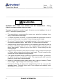
WARNING
WORKING WITH TOOLS AT HEIGHT CAN BE DANGEROUS.
objects can cause serious injury or death.
Falling
Trutest is designed to be used at height. It may be mounted solely on the top of
SOLOTM telescopic operating poles.
•
The manufacturer recommends that users wear protective headgear when
using Trutest above head height.
•
To ensure the safety of others, it is recommended that bystanders should be
moved out of the area of use when Trutest is being used at height.
•
Do not use Trutest unless it is securely mounted in the correct manner on
the specified operating poles. See section 3.6 of this manual for details.
•
Always ensure that the spring buttons on the operating poles and the stem at
the base of Trutest’s main unit are fully engaged, before raising the unit
above head height. Failure to do so can result in Trutest falling from the
working height.
•
Always ensure that the Trutest aerosol canister is firmly located and secured
in Trutest, before raising the unit above head height. This will mean that the
canister will not be displaced during operation.
•
Take great care when raising or lowering Trutest from a height. In particular,
be careful not to lose control of the poles. This requires some skill, and prior
practice in a safe area is recommended.
•
Beware of overhead electrical cables when using, raising or lowering Trutest
from a height. High voltages can cause injury or death.
•
Ensure that Trutest is always well supported by both the user and the
operating poles. This will reduce risk of user fatigue and instability when
operating the unit at height.
___________________________________________________________________
___________________________________________________________________
ii
PRIMARY INFORMATION
Issue:
2.1e
Trutest User Manual
Date: 01/12/08
__________________________________________________________________
__________________________________________________________________
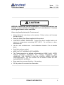
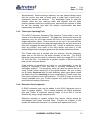
CAUTION
AEROSOL CANISTERS CAN BE HAZARDOUS. Pressurized containers can
explode if correct method of storage and use is not observed. Contents
can be ignited under certain conditions.
When using/handling/storing the Trutest aerosol:
•
Always follow the instructions on the canister. Failure to do so will increase
the risk of injury.
•
Read the Safety Data Sheet supplied with the product.
•
CONTENTS UNDER PRESSURE. Protect from direct sunlight and do not
expose to temperatures exceeding 120ºF (50ºC). Do not pierce or burn,
even after use.
•
Use in a well ventilated area. Avoid deliberate inhalation / Do not breathe
spray.
•
Avoid skin and eye contact.
•
KEEP OUT OF THE REACH OF CHILDREN.
•
The Trutest aerosol is not defined as flammable by §1500.3 (c)(6), 16CFR,
Federal Hazardous Substances Act, C.P.S.C. Regulations, USA.
HOWEVER, THE PRODUCT CAN BE IGNITED UNDER CERTAIN
CIRCUMSTANCES. DO NOT SPRAY ON A NAKED FLAME OR ANY
INCANDESCENT MATERIAL.
•
Keep away from sources of ignition – No smoking.
•
20% by mass of the contents are flammable.
__________________________________________________________________
__________________________________________________________________
PRIMARY INFORMATION
iii
Issue:
2.1e
Trutest User Manual
Date: 01/12/08
___________________________________________________________________
This page is intentionally blank
___________________________________________________________________
iv
PRIMARY INFORMATION
Issue:
2.1e
Trutest User Manual
Date: 01/12/08
__________________________________________________________________
ii.
1.
2.
3.
TABLE OF CONTENTS
i.
Safety Instructions
i
ii.
Table of Contents
v
iii.
Preface
viii
iv.
Important Notes for the User
ix
v.
Statement Of Guarantee And Liability
x
TECHNICAL DESCRIPTION
1
1.1. Why Test Sensitivity?
1
1.2. Why Test In-Situ?
1
1.3. Why Trutest?
1
1.4. Trutest Principles
2
INTRODUCTION TO TRUTEST
3
2.1. Introduction
3
2.2. Components
2.2.1. Main Unit
2.2.2. Control Unit
2.2.3. Test Aerosols
4
4
4
5
ASSEMBLY INSTRUCTIONS
7
3.1. General
7
3.2. Components of Trutest
3.2.1 The Control Unit
3.2.2. The Main Unit
3.2.3. Telescopic Operating Pole
3.2.4. Extension Poles (optional)
3.2.5. Battery Charger
3.2.6. Interconnecting Cable
3.2.7. Aerosol Canisters
3.2.8. Carry / Store Case
3.2.9. Pole Bag (optional)
8
8
9
13
13
14
14
14
15
15
3.3. Selecting and Fitting the Diaphragm Seals
15
3.4. Fitting the Aerosol Canister
16
3.5. Preparatory Checks
17
3.6. Assembling the Equipment
17
__________________________________________________________________
PRIMARY INFORMATION
v
Issue:
2.1e
Trutest User Manual
Date: 01/12/08
___________________________________________________________________
4.
5.
6.
OPERATING INSTRUCTIONS
21
4.1. Preparing to Test
21
4.2. Selecting the Detector Type
22
4.3. Selecting the Test Mode
4.3.1. Max/Min Test
4.3.2. Fast Ramp Test
4.3.3. Slow Ramp Test
23
23
24
25
4.4. Selecting a Detector Setup for Max/Min Mode
25
4.5. Entering New Test Parameters for Max/Min Mode
26
4.6. Starting the Test Sequence
29
4.7. The End of the Test
31
4.8. Completing the Test and Clearing the Smoke
31
RESULTS
33
5.1. General Objective of Results
33
5.2. Results Screen for Ramp Test
33
5.3. Results Screen for Max/Min Test
34
5.4. Warnings Shown on Result Screens
35
5.5. Stored Results
36
5.6. Interpretation of Results
37
5.7. Action if a Detector Fails a Test with Trutest
38
SERVICE AND MAINTENANCE
39
6.1. User Servicing
6.1.1. Cleaning
6.1.2. Damage Requiring Servicing
6.1.3. Replacing the Fuse
6.1.4. User Calibration Check
6.1.5. Membrane Condition Check
39
39
39
40
40
40
6.2. Annual Servicing
41
6.3. Service Screen
41
6.4. Warning Messages
6.4.1. Low Battery
6.4.2. Service Warnings
6.4.3. Empty Aerosol Can
6.4.4. Sensor Drift
6.4.5. Wiring Fault
6.4.6. System Error
6.4.7 Min/Max Error
42
42
42
43
44
44
44
45
___________________________________________________________________
vi
PRIMARY INFORMATION
Issue:
2.1e
Trutest User Manual
Date: 01/12/08
__________________________________________________________________
6.5. Troubleshooting Guide
7.
8.
46
FREQUENTLY ASKED QUESTIONS
47
7.1. Questions on Usage
47
7.2. Questions on Sensitivity & Calibration
48
7.3. Questions on effects of Temperature & Humidity
49
7.4. Questions on Trutest Aerosol
50
7.5. Questions on Batteries and Power
51
7.6. Questions on User Input / User Interface
51
7.7. Questions on Results and Displays
52
7.8. Questions on Weight, Insulation and Practical Usage
52
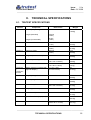
TECHNICAL SPECIFICATIONS
55
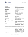
8.1. Trutest Specifications
55
8.2. Aerosol Data
57
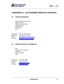
APPENDIX A - AUTHORIZED SERVICE CENTERS
A1
A.1 United Kingdom
A1
A.2 United States of America
A1
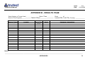
APPENDIX B - RESULTS PAGE
B1
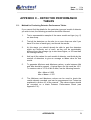
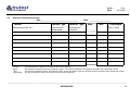
APPENDIX C. - DETECTOR PERFORMANCE TABLES
C.1. Method for Producing Detector Performance Tables
C.2 Detector Performance Sheet
C1
C1
C2
__________________________________________________________________
PRIMARY INFORMATION
vii
Issue:
2.1e
Trutest User Manual
Date: 01/12/08
___________________________________________________________________
iii.
PREFACE
This manual is:
1)
designed to outline the correct methods of operating and
maintaining your Trutest system.
2)
written in a logical order for first time users.
3)
designed to be detailed. It is not, however, possible to cover all
situations, possible problems or questions.
4)
a controlled document and it is important that the User Registration
card be returned.
For further information contact either:
a)
the supplier of this manual and system
b)
an authorized service center
c)
No Climb Products Ltd.,
Edison House,
163 Dixon’s Hill Road
Welham Green,
Herts.
AL9 7JE
UK
or
always quoting the serial number of your Trutest in any communication.
___________________________________________________________________
viii
PRIMARY INFORMATION
Issue:
2.1e
Trutest User Manual
Date: 01/12/08
__________________________________________________________________
iv.
IMPORTANT NOTES FOR THE USER
Safety
Read this manual and the Safety Instructions before using Trutest. The user
must be thoroughly acquainted with the procedures in the manual to ensure
maximum safety in use.
User Registration Card
Copy the serial number onto your registration card and return in order to register
the product with the manufacturer.
Power
The equipment is supplied with a universal battery charger. Remove from outlet
when not in use.
Storage
Avoid places subject to direct sunlight or extremely high or low temperatures.
Avoid damp or dusty places. Avoid unstable locations and high places from
which the unit could fall. Always store components in carry case provided.
Spillage
Care should be taken so that objects do not fall onto, or liquids spilled into, the
enclosures through the openings. Do not block the openings. Avoid exposure to
rain.
Charging
Do not over-charge the NiCd Battery (charge overnight or 16 hours maximum).
Charge when "Low Battery" warning is displayed. Only use the battery charger
provided with this equipment. Recharge battery when new, or after prolonged
periods of disuse.
Electrical Connections
Do not force any connections. All connections should be made with the power
off. Only fit fuses of the recommended size and type (see Specifications, section
8).
Warranty
Service and calibration must be performed by the manufacturer or by an
approved service center (see page (viii), Statement of Guarantee and Liability).
Trutest has no internal user-serviceable parts. Do not remove any covers or
labels. Unauthorized repair or adjustments will invalidate all warranties.
Care
Trutest is a test instrument suitable for use in the field. However, the user
should exercise care, as with any item of high caliber electronic test equipment.
Damage due to misuse will invalidate all warranties.
__________________________________________________________________
PRIMARY INFORMATION
ix
Issue:
2.1e
Trutest User Manual
Date: 01/12/08
___________________________________________________________________
v.
STATEMENT OF GUARANTEE AND LIABILITY
No Climb Products Ltd. warrants this Trutest system described herein to be free from defect in material and
factory workmanship for a period of one year from the date of shipment and agrees to repair such products
which, under normal usage and service, disclose the defect to be the fault of No Climb Products. No Climb
Products' obligation under this warranty relates to the original purchaser and is limited to a return of the
purchase price, or at the sole discretion of No Climb Products Ltd., to the repair or replacement of the
system or of any of its constituent parts which may prove to be defective. For this guarantee to be valid, any
material or part alleged to be defective is to be returned to No Climb Products Ltd., or an authorized service
center, with prior notification and with prior approval, in writing, fully insured and transport prepaid by the
purchaser, within 12 months from date of shipment from the factory.
This warranty shall not apply to any unit or to any part of parts of any unit that has or have been:
1.
2.
3.
Subjected to misuse, abuse, negligence or accident.
Connected, installed, operated, adjusted or serviced other than in accordance with instructions
furnished by No Climb Products Ltd.
Repaired, modified or otherwise worked on by any person not authorized by No Climb Products
Ltd., so that in our opinion the performance or reliability of the instrument has been impaired.
Subject as above No Climb Products Ltd. reserves the right to make replacements with equivalent
merchandise and to effect changes at any time in the specification, design or construction of the system
without incurring obligation to make any corresponding changes in units previously delivered.
No Climb Products Ltd. accepts no liability for the repair, replacement or substitution or adjustment of any
detector which has not been tested in conformity with the instructions for use of the Trutest system as
detailed in this manual.
No Climb Products Ltd. assumes no liability for consequential or contingent damages for defective systems
covered by this warranty, failure of delivery in whole or in part or for any other cause.
No Climb Products Ltd. assumes no liability for the consequential loss or damage to property or injury to
persons resulting from the malfunctioning of fire protection systems or their components which may have
been tested with this product. The safe working condition of fire systems and their ability to respond to
cases of real fire is neither guaranteed nor implied by tests carried out with this product.
This warranty and the manual to which it is attached constitute the agreement of the buyer and the seller so
that no terms conditions or agreements purporting to modify the terms hereof shall be binding unless
previously made in writing and signed by an authorized signatory of No Climb Products Ltd.
Patents
This product is covered by U.S. and European patents. Other international patents pending.
European Patent No. (GB & FR)
German Patent No.
U.S.A. Patent No.
Note:
0698262
69404648.5
5670946
Because our policy is one of continuous improvement, details of products described within this
publication are subject to change without notice. All information provided within this publication is
believed to be correct at the time of going to press. Every effort has been made to ensure the
accuracy of information, which is provided in good faith, but nothing contained herein is intended to
incorporate any representation or warranty either express or implied or to form the basis of any
legal relations between the parties hereto, additional to or in lieu of such as may be applicable to a
contract of sale and purchase.
___________________________________________________________________
x
PRIMARY INFORMATION
Issue:
2.1e
Trutest User Manual
Date: 01/12/08
__________________________________________________________________
1.
TECHNICAL DESCRIPTION
1.1. WHY TEST SENSITIVITY?
Over-sensitive detectors are more prone to false alarms. Under-sensitive
detectors tend to delay the alarm signal (if they alarm at all). The
sensitivity of modern smoke detectors are well controlled during
manufacture but detectors in the field are subject to airborne
contaminants, aging and outside interference - factors which can all
significantly affect sensitivity.
Most detectors currently installed have no facilities for monitoring their
own condition. Even analogue addressable sensors can only monitor the
'clean air' response levels, and cannot allow for contamination of the
mesh covering entry to the sensing chamber. In the USA, NFPA Fire
Code 72, requires frequent sensitivity testing, and local codes are often
more stringent.
1.2. WHY TEST IN-SITU?
In-situ testing of smoke detector sensitivity greatly reduces the time and
cost of testing a detector for response sensitivity. The detector does not
need to be removed for testing, and does not need to be tested once for
sensitivity, and again for system response. In-situ sensitivity testing is the
only way of ensuring that the undisturbed detector, as installed, is
functioning correctly.
1.3. WHY TRUTEST?
A fire system is an expensive and sophisticated apparatus designed to
protect life and property. It is imperative that it functions as designed. By
delivering a test aerosol of known quality, type and particle size whose
concentration is steadily increased, Trutest provides a quantitative
assessment of sensitivity, as well as confirming that the detector is
capable of receiving an external smoke stimulus and that entry to the
sensing chamber is not blocked.
__________________________________________________________________
TECHNICAL DESCRIPTION
1
Issue:
2.1e
Trutest User Manual
Date: 01/12/08
___________________________________________________________________
1.4. TRUTEST PRINCIPLES
Trutest is fully automatic. The user merely determines which type of
detector is under test and which type of test he wishes to perform. This
information is input via a simple menu prompt system into the control unit
carried on a shoulder strap. The installed detector is covered with the
transparent cup of the main unit and the keypad is pressed to begin the
test.
Trutest automatically introduces to the installed detector, a test aerosol of
known quality, whose concentration is controlled by the microprocessor in
the control unit. The aerosol concentration is constantly increased, while
being read by a stable and extremely accurate light obscuration sensor
housed in the head of the main unit. A single keypad button press stops
the test and the detector's response to the test aerosol is output on the
digital display of the control unit. This is then compared with the minimum
and maximum values specified for that detector.
For types of test that Trutest will perform, see section 4.3.
___________________________________________________________________
2
TECHNICAL DESCRIPTION
Issue:
2.1e
Trutest User Manual
Date: 01/12/08
__________________________________________________________________
2.
INTRODUCTION TO TRUTEST
2.1. INTRODUCTION
Trutest is a technologically advanced, fully field-portable device for in-situ
testing of smoke detector sensitivity. The equipment is suitable for testing
photoelectric and ionization detectors; conventional, addressable and
analogue addressable.
WARNING
• Before operating Trutest, read the
Safety Instructions at the start of this
User Manual. Failure to do so will
increase the risk of injury.
The system consists of a main unit mounted on an extendable pole, with
a separate control unit and battery pack connected by an umbilical cable.
The main unit comprises a cup with a membrane seal which fits around a
ceiling mounted detector, and a test aerosol canister with control valve,
and high accuracy smoke obscuration sensor.
The tests are conducted by raising the unit to the detector on the ceiling,
and then passing a carefully controlled amount of synthetic smoke
particles through the detector. The user waits for the detector to activate,
and then manually stops the test and the sensitivity result is displayed by
Trutest.
The control unit incorporates a microprocessor, keyboard and display,
and controls the complete test sequence. A number of standard test
types are available, allowing for manual control of the tests, as well as a
"pass/fail" type test.
Trutest is designed to be used in the field for commissioning and periodic
maintenance of all types of point smoke detectors. All the tests are
designed to be employed from the ground by a service engineer, whilst
the detectors are still in position, connected and working, providing an
accurate simulation of a real fire.
The sensitivity test provides a quantitative test, providing a final value in
%/ft for each detector, which indicates the actual sensitivity of the detector
at that time. The readings are correlated to the UL smoke box, as
described in UL268.
__________________________________________________________________
INTRODUCTION TO TRUTEST
3
Issue:
2.1e
Trutest User Manual
Date: 01/12/08
___________________________________________________________________
2.2. COMPONENTS
The complete set of equipment is comprised of the following main
components (not all of which are necessarily supplied):
•
•
•
•
•
•
•
•
•
•
•
Main unit
Control unit
Synthetic test aerosols
Two interconnecting cables (differing lengths)
Telescopic operating pole
Height adjustment clamp
Extension pole (optional)
Two membrane seals (differing apertures)
Battery charger
Carry case
User manual (this document)
The first three are described in more detail below. See section 3,
Assembly Instructions, for more detailed descriptions of all components:
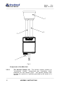
2.2.1. Main Unit
The main unit is mounted on a telescopic operating pole, and consists of
a transparent test cup to surround the detector, a high-precision smoke
sensor, various control components and internal chambers. The foot of
the telescopic operating pole rests on the ground, supporting the main
unit when in use.
WARNING
Trutest is used above head height.
• Read the Safety Instructions at the start
of this User Manual. Failure to do so
will increase the risk of injury.
2.2.2. Control Unit
The service engineer usually carries this unit on a shoulder strap. It
consists of a microprocessor, keypad and display, and the battery pack
for the Trutest. The keypad and display allow the engineer to start and
stop tests, change the operating parameters of the system, specify the
type of detector being tested and the type of test to be performed. It also
provides feedback of the test sequence and results.
___________________________________________________________________
4
INTRODUCTION TO TRUTEST
Issue:
2.1e
Trutest User Manual
Date: 01/12/08
__________________________________________________________________
2.2.3. Test Aerosols
Trutest uses a form of synthetic test smoke stored in a pressurized
aerosol container. This produces a fine mist of aerosol particles to
simulate the smoke from a real fire. The aerosol formula and canister are
specific to Trutest, and cannot be substituted with any other test aerosol.
CAUTION
Trutest uses a pressurized aerosol canister.
• Read the Safety Instructions at the start
of this User Manual. Failure to do so
will increase the risk of injury.
• Always follow the instructions on the
canister.
__________________________________________________________________
INTRODUCTION TO TRUTEST
5
Issue:
2.1e
Trutest User Manual
Date: 01/12/08
___________________________________________________________________
This page is intentionally blank
___________________________________________________________________
6
INTRODUCTION TO TRUTEST
Issue:
2.1e
Trutest User Manual
Date: 01/12/08
__________________________________________________________________
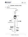
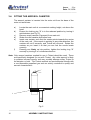
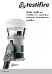
3.
ASSEMBLY INSTRUCTIONS
3.1. GENERAL
Trutest is used in the following assembly:
Fig. 1
__________________________________________________________________
ASSEMBLY INSTRUCTIONS
7
Issue:
2.1e
Trutest User Manual
Date: 01/12/08
___________________________________________________________________
3.2. COMPONENTS OF TRUTEST
3.2.1 The Control Unit
Fig. 2
Carried on a shoulder strap by the operator, the control unit incorporates
a microprocessor, LCD display, keyboard and rechargeable battery pack.
Commonly used test limits may be pre-stored within the microprocessor
for instant recall when required (see Section 4.5., Entering New Test
Parameters for Max/Min Mode). At each stage in the test sequence the
control unit displays to the user what is happening through visual displays
and audible prompts. The control unit is connected to the main unit via
the interconnecting cable.
Components of the Control Unit:
3.2.1.1
The keyboard (A): A membrane keypad incorporating tactile
contacts that have a soft click action to provide confirmation of operation.
3.2.1.2
The display (B): A 20 character x 4 line LCD display module
utilizing supertwist numatic technology to provide a high contrast, wide
viewing angle display.
3.2.1.3
The microprocessor within the control unit controls the operation
of the whole system. It provides a user interface via the keypad and LCD
display and controls the aerosol generation, circulation and sensing within
the main unit.
___________________________________________________________________
8
ASSEMBLY INSTRUCTIONS
Issue:
2.1e
Trutest User Manual
Date: 01/12/08
__________________________________________________________________
3.2.1.4
The rechargeable battery pack within the control unit will provide
sufficient power for a day of testing. It may then be recharged
overnight via the battery charger provided.
Note: The control unit features an auto power down. If left on, it will
automatically switch off after fifteen minutes, thereby saving battery
power.
3.2.1.5
a)
b)
c)
d)
e)
f)
3.2.1.6
The sounder within the control unit produces the following sounds
to prompt the user at different stages in the test sequence:
When a key is pressed - half second beep.
During initialization stage - a single beep every five seconds.
During smoke test stage - a slow double beep every five seconds.
If an error occurs - a single two-second continuous beep to draw
the attention of the user to the display (see section 6.4.).
During max/min testing - a rapid double beep at the min value, and
a rapid triple beep at the max value (see section 4.3.1.).
During clearing stage – a rapid double beep when the 50% clear
level is reached and Trutest should be removed from the detector
under test (see section 4.8.3.).
Calibration is factory adjusted and set. Data for the calibration is
stored in the control unit during manufacture. Between annual
services, there is no need for any interim adjustments, since
Trutest is self calibrating.
IMPORTANT: Since the control unit maintains the calibration of the
main unit, and should never be interchanged with any other control unit.
The serial numbers on the main and control units should always match.
3.2.2. The Main Unit
The main unit is a lightweight assembly that is lifted to cover the detector.
It comprises the aerosol dispenser, central aerosol reservoirs, sensor
tube, transparent detector cup and return tube. Similar to a smoke tunnel,
the test aerosol produced from the canister is taken up the sensor tube
where it is measured, before passing through the transparent detector
cup covering the detector under test and returning down the return tube
for recirculation. The aerosol concentration is continually monitored by
the microprocessor via the sensor. The transparent detector cup enables
the LED alarm indicator of the detector to be seen illuminating on
successful activation of the alarm.
Note: The main unit contains no user-serviceable parts. The operator needs
only to replace aerosol cans from time to time. The unit should not be
opened by the user and any action in this respect other than by an
authorized service center will invalidate all warranties and guarantees.
__________________________________________________________________
ASSEMBLY INSTRUCTIONS
9
Issue:
2.1e
Trutest User Manual
Date: 01/12/08
___________________________________________________________________
C
B
D
A
Fig. 3
Components of the Main Unit:
3.2.2.1
The Aerosol Canister (A). The aerosol canister contains an
"environment friendly", pressurized gas formulation which
produces the test aerosol cloud. The aerosol particle sizes
simulate the spectrum of particles generated by the smoke of a
real fire.
___________________________________________________________________
10
ASSEMBLY INSTRUCTIONS
Issue:
2.1e
Trutest User Manual
Date: 01/12/08
__________________________________________________________________
__________________________________________________________________
CAUTION
AEROSOL CANISTERS CAN BE HAZARDOUS.
Pressurized
containers can explode if correct method of storage and use is not
observed. Contents can be ignited under certain conditions.
When using/handling/storing the Trutest aerosol:
•
Always follow the instructions on the canister. Failure to do so will
increase the risk of injury.
•
Read the Safety Data Sheet supplied with the product.
•
CONTENTS UNDER PRESSURE. Protect from direct sunlight and
do not expose to temperatures exceeding 120ºF (50ºC). Do not
pierce or burn, even after use.
•
Use in a well ventilated area. Avoid deliberate inhalation / Do not
breathe spray.
•
Avoid skin and eye contact.
•
KEEP OUT OF THE REACH OF CHILDREN.
•
The Trutest aerosol is not defined as flammable by §1500.3 (c)(6),
16CFR, Federal Hazardous Substances Act, C.P.S.C. Regulations,
USA. HOWEVER, THE PRODUCT CAN BE IGNITED UNDER
CERTAIN CIRCUMSTANCES. DO NOT SPRAY ON A NAKED
FLAME OR ANY INCANDESCENT MATERIAL.
•
Keep away from sources of ignition – No smoking.
•
20% by mass of the contents are flammable.
__________________________________________________________________
The number of detectors that can be tested with one aerosol canister will
depend on the type of test and state of the detector under test. Typically
one aerosol canister may be expected to perform over one hundred tests.
Once fitted into its retaining cylinder, the aerosol dispenser is activated by
a solenoid within the main unit.
__________________________________________________________________
ASSEMBLY INSTRUCTIONS
11
Issue:
2.1e
Trutest User Manual
Date: 01/12/08
___________________________________________________________________
Note: Only aerosol cans specifically marked for use within Trutest can be used
within this device. The use of any other aerosols will invalidate results
and may cause irreparable damage to Trutest. Always re-order the same
aerosol part number.
3.2.2.2
The Solenoid. Under the control of the microprocessor the
solenoid mechanism operates the pressurized aerosol canister (A)
to release short bursts of aerosol into the aerosol reservoir. This
dense aerosol cloud is slowly fed, by a controlled fan, into the
sensing loop comprising the sensing chamber, sensor tube (B),
detector cup (C) and return tube (D).
The aerosol density in the sensing loop has a much lower
concentration than in the reservoir, and it is this aerosol cloud
which is circulated up the sensor tube, past the smoke detector
under test, and back down the return tube. The fans within the
sensing loop and the design of the loop tube are arranged so that
the airspeed over the smoke detector is maintained at
approximately 0.6ft/s or 1.3ft/s for ionization and photoelectric
detectors respectively - the optimum airspeed specified to operate
smoke detectors.
3.2.2.3
The Sensor measures the aerosol concentration in the sensor
tube before it enters the detector cup. Trutest uses a very stable
and accurate light obscuration sensor. The sensor is fully selfmonitoring and self-calibrating in the event of any contamination
on the optical surfaces. The output derived from it corresponds to
the prescribed method for sensitivity measurement specified for
photoelectric smoke detectors in the UL268 standard for point type
smoke detectors. An internal correlation to ionization detectors
(within Trutest) has been established and verified to enable
accurate sensitivity readings to be made of both ionization and
photoelectric detectors.
3.2.2.4
The Detector Cup (C) is transparent, enabling the user to see the
LED of the detector when it activates. The detector is sealed
within the cup by a diaphragm seal. A red stripe is provided on
one side of the cup that may be aligned with a feature of the
detector, such as its LED, to indicate the detector’s orientation in
the cup. It is recommended that future or repeat tests on the same
detector are performed in the same orientation in order to minimize
directional dependence i.e. the variation in reading due to detector
orientation relative to the direction of airflow in the cup.
3.2.2.5
Diaphragm Seals: Two interchangeable silicone diaphragm seals
are supplied with the basic kit. Each one is color coded for a
particular range of detector sizes (see section 8.1., Trutest
___________________________________________________________________
12
ASSEMBLY INSTRUCTIONS
Issue:
2.1e
Trutest User Manual
Date: 01/12/08
__________________________________________________________________
Specifications). Before testing a detector, the user should always check
that the correct size seal is being used in order that a good seal is
maintained around the detector. The diaphragm helps to seal the
detector within the cup, reducing leaks, and together with the slight
positive pressure within the sensing loop, preventing the ingress of clean
air into the sensing loop after the aerosol concentration has been
measured by the sensor.
3.2.3. Telescopic Operating Pole
The SOLO Telescopic Operating Pole supports Trutest while in use, by
means of four telescopic sections. The upper two sections will lock at full
extension only, but the lower section will lock at any position using the
height adjustment clamp. Trutest mounts on the top of the pole directly
and the pole is erected to the desired height using the top two sections of
pole first, engaging the spring buttons fully. If there is insufficient room to
erect any section, then move to the third section and erect it to the
desired height before clamping gently with the height adjustment clamp.
The Trutest main unit is located over the detector, and the telescopic
poles rest on the floor for the entire duration of the test. The SOLO
telescopic pole permits tests on detectors within the range 6ft 5" to 16ft
10" from the floor. For detectors at greater heights, a SOLO extension
pole can be used (see below).
If the detector is mounted at an angle (i.e. not horizontally), it may be
simpler to exchange it with one that is mounted horizontally in an
accessible position. The sensitivity tests can then be carried out on it
using Trutest, before returning it to its original position. Be sure to carry
out a further functional test on both detectors which have been moved
(as distinct from the sensitivity test just completed by Trutest) once they
have been restored to their final positions. The SOLO range of tools are
usually available from your Trutest supplier and permit simple removal
and functional testing of detectors.
3.2.4. Extension Poles (optional)
A SOLO extension pole can be added to the SOLO telescopic pole to
reach to greater heights. This is added between the SOLO telescopic
pole and Trutest. A maximum working height of up to 20ft 8” can be
obtained by using a single extension pole.
Detectors mounted at greater heights that require testing should be
interchanged with those mounted lower. (Contact the supplier of this
system for additional information on removal and replacement tools).
__________________________________________________________________
ASSEMBLY INSTRUCTIONS
13
Issue:
2.1e
Trutest User Manual
Date: 01/12/08
___________________________________________________________________
WARNING
Trutest is used above head height.
• Read the Safety Instructions at the start
of this User Manual. Failure to do so
will increase the risk of injury.
• When using Trutest at height, extreme
care should be taken. The unit must be
carefully controlled when mounted on
poles above head height. At great
heights this requires some skill.
3.2.5. Battery Charger
A 12V NiCd battery is incorporated within the control unit. When fully
charged it will enable the operator to complete more than one day of
continuous testing. The total number of tests obtainable from one charge
depends on the type of test that Trutest is asked to perform and the
sensitivity level and type of detector under test. Battery Chargers for
North America, Japan, Europe, Australia and the UK are available, and a
charger for your country should be included in the kit.
To charge the battery, connect the charger to the outlet and to the control
unit charger socket (see Fig.2). Charging takes 14-16 hours if the battery
is completely exhausted. Do not leave the charger connected indefinitely.
Overnight charging is recommended prior to using Trutest. The charger
and the Trutest base unit may become slightly warm during charging.
This is quite normal.
3.2.6. Interconnecting Cable
Connects the main unit of Trutest to the control unit. Two lengths of cable
are supplied, 2.5m and 5m, to suit operation at different heights. The
user should use the most convenient length in each application.
3.2.7. Aerosol Canisters
Depending on the type of test and the sensitivity level of the detector
under test, a single aerosol canister should perform over one hundred
tests. Canisters are usually supplied in quantities of twelve cans.
___________________________________________________________________
14
ASSEMBLY INSTRUCTIONS
Issue:
2.1e
Trutest User Manual
Date: 01/12/08
__________________________________________________________________
CAUTION
Trutest uses a pressurized aerosol canister.
• Read the Safety Instructions at the start
of this User Manual. Failure to do so
will increase the risk of injury.
• Always follow the instructions on the
canister.
3.2.8. Carry / Store Case
Trutest (excepting SOLO telescopic and extension poles) is packed in a
custom case with carrying handle and shoulder strap. Each component
has its own compartment. All components should be stored neatly in the
case when not in use.
3.2.9. Pole Bag (optional)
A separate pole bag is available for the SOLO telescopic operating pole
and extension pole. This is designed to attach neatly and securely to the
Trutest carry case such that all equipment is easily transported together.
3.3. SELECTING AND FITTING THE DIAPHRAGM SEALS
Two interchangeable silicone diaphragm seals are supplied with the basic
kit. These fit to the top of the transparent detector cup and are used to
seal the detector under test within the cup. The seals each cover a
different range of detector sizes and are color coded for easy reference.
The pink diaphragm is suitable for testing detectors of diameter from 2.8
to 4.3 inches. The gray diaphragm is suitable for testing detectors of
diameters 3.7 to 5.7 inches. Select and fit the required diaphragm for the
detectors to be tested.
__________________________________________________________________
ASSEMBLY INSTRUCTIONS
15
Issue:
2.1e
Trutest User Manual
Date: 01/12/08
___________________________________________________________________
3.4. FITTING THE AEROSOL CANISTER
The aerosol canister is inserted into the main unit from the base of the
main unit as follows:
a)
b)
c)
d)
e)
f)
Locate the main unit at a convenient working height, not above the
head.
Ensure the locking ring "A" is in the released position by turning it
anticlockwise (see Fig. 5)
Remove empty canister (if present) from main unit.
Shake the new canister well before use.
Insert new canister such that the nozzle points towards the center
of the main unit. If the nozzle is pointing in any other direction, the
canister will not fit correctly, and Trutest will not work. Rotate the
canister as you insert it so that you can feel the nozzle locate
correctly.
Pressing can firmly up into position, tighten the locking ring "A"
securely by turning it in a clockwise direction.
Note: Only aerosol canisters marked for use in Trutest should be used. These
are specifically designed for use with Trutest. Any other aerosol is likely
to produce incorrect results, and may possibly damage either Trutest or
the detector or both. The Trutest aerosols are environmental friendly with
a non-flammable propellant gas and are strictly controlled in quality and
aerosol characteristics.
A
Fig. 5
___________________________________________________________________
16
ASSEMBLY INSTRUCTIONS
Issue:
2.1e
Trutest User Manual
Date: 01/12/08
__________________________________________________________________
3.5. PREPARATORY CHECKS
Before assembling Trutest for use, check the following:
a)
Ensure that the battery in the unit is fully charged.
b)
Ensure that you have the correct poles and extensions required to
access the height of the detector.
c)
For detectors fitted at heights greater than normal ceiling height,
ensure that you have suitable removal tools to enable removal of
detectors at height if the detector fails the test and needs replacing.
Such tools are usually available from the supplier of Trutest.
d)
Ensure that all safety precautions are taken, including additional
precautions for working at height. See the Safety Instructions at
the start of this manual.
e)
Ensure that you have a sufficiently full can of aerosol before
starting any testing. Check that you have a full spare can too.
f)
Ensure that the serial number on the main unit is the same as on
the control unit. Trutest calibrates the main unit and control units
together, and they should not be interchanged.
3.6. ASSEMBLING THE EQUIPMENT
a)
Determine the type and model of detector to be tested and select
the correct diaphragm seal for that detector from the size
specifications. Fit this securely to the top of the transparent plastic
cup of the main unit.
b)
Fit aerosol canister as described above, ensuring that the nozzle of
the aerosol has been inserted correctly into the main unit and is
pointing toward the center of Trutest.
__________________________________________________________________
ASSEMBLY INSTRUCTIONS
17
Issue:
2.1e
Trutest User Manual
Date: 01/12/08
___________________________________________________________________
WARNING
•
Always ensure that the Trutest
aerosol canister is firmly located and
secured in Trutest, before raising the
unit above head height.
This will mean that the canister will not
be displaced during operation.
c)
Attach the interconnecting cable between Trutest main unit and
control unit of appropriate length for the height you will be working.
d)
Fit Trutest to the top of the SOLO telescopic operating pole, or to
the top of an extension pole, should greater height than approx.
17ft. be required.
Rotate the top section of the SOLO telescopic pole or the
extension pole when Trutest is positioned on top, to lock the spring
button.
e)
Next, if an extension pole is used, fit the base of the extension pole
to the top of the SOLO telescopic operating pole. Always
assemble with the poles in an upright position, adding the
extension to the bottom of Trutest, and then adding the telescopic
pole beneath the extension pole, rather than by assembling the
entire length on the floor and lifting. Lifting the unit from the
horizontal may lead to the poles becoming damaged. Check that
the extension pole, if fitted, is latched properly to the SOLO
telescopic operating pole (by rotating the extension until the button
engages) before extending the latter as detailed below.
___________________________________________________________________
18
ASSEMBLY INSTRUCTIONS
Issue:
2.1e
Trutest User Manual
Date: 01/12/08
__________________________________________________________________
WARNING
•
Do not use Trutest unless it is
securely mounted in the correct
manner on the specified operating
poles.
•
Always ensure that the spring buttons
on the operating poles and the stem
at the base of Trutest’s main unit are
fully engaged, before raising the unit
above head height.
Failure to observe these instructions can
result in Trutest falling from the working
height.
f)
Place yourself and the Trutest unit directly below the detector to be
tested and raise the unit towards the detector. Starting with the top
(smallest diameter) pole of the SOLO Telescopic Operating Pole,
extend each section to its maximum height and latch the spring
buttons by rotating the pole until the button engages.
g)
When you reach the stage when the next section will not extend
fully, use the lowest telescopic section to finally raise the unit until
Trutest's clear cup is positioned over the detector, ensuring that
the inlet vents of the detector are well sealed within the cup by the
diaphragm seal. Gently tighten the height adjustment clamp to
retain this position, with the base of the SOLO Telescopic
Operating Pole resting on the ground.
h)
The whole assembly should support its own weight, but the user
should ensure that it is stable at all times. Never leave the poles
and Trutest unattended, even for short periods.
__________________________________________________________________
ASSEMBLY INSTRUCTIONS
19
Issue:
2.1e
Trutest User Manual
Date: 01/12/08
___________________________________________________________________
This page is intentionally blank
___________________________________________________________________
20
ASSEMBLY INSTRUCTIONS
Issue:
2.1e
Trutest User Manual
Date: 01/12/08
__________________________________________________________________
4.
OPERATING INSTRUCTIONS
4.1. PREPARING TO TEST
a)
Check that the unit has been correctly assembled as described in
the assembly instructions (Chapter 3) before turning on the power.
In particular, ensure that the battery has been charged, and the
aerosol canister has been correctly installed (see section 3.4.,
Fitting the Aerosol Canister).
WARNING
•
Always ensure that the Trutest
aerosol canister is firmly located and
secured in Trutest, before raising the
unit above head height.
This will mean that the canister will not
be displaced during operation.
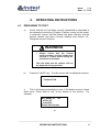
b)
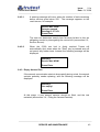
Press the "On/Off" key. The title screen will be displayed as below.
Trutest V2.1d
c)
This is followed automatically by one of the default screens (those
which have “Press Start to test” at the bottom of the screen). For
example:
NO_NAME_01 ion
min=1.00
max=2.00
Press Start to test
or
__________________________________________________________________
OPERATING INSTRUCTIONS
21
Issue:
2.1e
Trutest User Manual
Date: 01/12/08
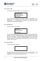
___________________________________________________________________
Fast ramp
photo
hi profile
Press Start to test
or
Slow ramp
ion
hi profile
Press Start to test
d)
The user must determine which type and model of detector is to be
tested, and which type of test is to be performed. The control unit
requires up to three pieces of information to be set prior to performing the
test.
i)
ii)
iii)
Detector type - photoelectric or ionization and high or low
profile.
Test mode - fast ramp, slow ramp or max/min mode.
The setup number (if testing in max/min mode).
This information is entered into the control unit by means of the keypad.
The current settings are displayed on the screen.
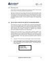
4.2. SELECTING THE DETECTOR TYPE
Trutest has a different smoke and air flow characteristic to that of the UL
smoke box. Conversion factors are used to achieve good correlation
between Trutest and the UL smoke box. These conversion factors are
different for photoelectric, ionization and the height profile of the detector.
Therefore, the user must select the correct detector type before
beginning each test.
Use the "Det. type" key on the keypad to sequence through the detector
types displayed on the screen. The four options are:
- photo lo profile
- photo hi profile
- ion lo profile
- ion hi profile
for low profile photoelectric detectors
for high profile photoelectric detectors
for low profile ionization detectors
for high profile ionization detectors
Detectors that protrude more than one third into the cup should be
considered as high profile.
___________________________________________________________________
22
OPERATING INSTRUCTIONS
Issue:
2.1e
Trutest User Manual
Date: 01/12/08
__________________________________________________________________
4.3. SELECTING THE TEST MODE
Use the "Test mode" key on the keypad to toggle between these three
types of test:
1. Max/min (see section 4.3.1.)
2. Fast ramp (see section 4.3.2.)
3. Slow ramp (see section 4.3.3.)
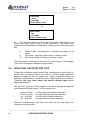
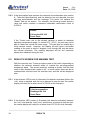
4.3.1. Max/Min Test
This is used to carry out a quantitative check. Trutest tests whether the
sensitivity of the detector falls within an acceptance band or range of
sensitivities. It does this by ramping up the concentration of aerosol in the
sensing loop, notifying the user when certain pre-determined levels of
sensitivity are reached. These parameters are entered by the user
against the name of the detector according to its sensitivity rating (see
section 4.5., Entering New Test Parameters for Max/Min Mode). To
choose which detector setup to use for a max/min test, see Section 4.4.,
Selecting a Detector Setup for Max/Min Mode.
The user stops the test when the detector alarms, as usual, and Trutest
reports either a ‘Pass’, a ‘Fail Over-sensitive’ or ‘Fail Under-sensitive’
result (see section 5.3., Results Screen for Max/Min Test). This result is
determined by whether the alarm occurred before, after, or in between the
expected minimum and maximum sensitivity values for the detector.
During the test, when the obscuration in the sensing loop reaches the
level of the minimum sensitivity parameter entered, a rapid double beep is
heard, and a small indicator arrow appears on the display adjacent to the
minimum value. Similarly, when the obscuration reaches the level of the
maximum sensitivity parameter, a rapid triple beep is heard and the arrow
moves to the maximum value. It is simple and quick to tell whether the
detector has alarmed within its stated sensitivity band.
OBSCURATION
FULL SCALE
FAIL INSENSITIVE
MAX
PASS
MIN
FAIL
OVERSENSITIVE
TIME
__________________________________________________________________
OPERATING INSTRUCTIONS
23
Issue:
2.1e
Trutest User Manual
Date: 01/12/08
___________________________________________________________________
Max. is the maximum reading of obscuration in %/ft required to activate
the detector. This figure can be determined from the higher sensitivity
rating of the detector (printed on the label on the base of most UL listed
detectors or from the manufacturers’ data sheets) plus any uncertainties
in the measurement. For example, Trutest measurement uncertainty (see
section 8.1., Trutest Specifications). Detectors which fail to alarm at, or
before, this level are deemed to be under-sensitive.
Min. is the minimum reading of obscuration at, or below, which the
detector should not activate. This figure can be determined from the lower
sensitivity rating of the detector (printed on the label on the base of most
UL listed detectors or from the manufacturers’ data sheets) minus any
uncertainties in the measurement. For example, Trutest measurement
uncertainty (see section 8.1., Trutest Specifications). Detectors that
activate at, or prior, to this level are deemed to be over-sensitive.
Detector name is a ten character alphanumeric, user selectable label.
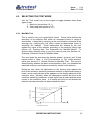
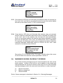
4.3.2. Fast Ramp Test
This is used to carry out a fast quantitative check. Trutest increases the
concentration of aerosol in the measuring cup and records the point at
which the detector alarms. This figure may then be compared with the
minimum and maximum acceptable levels specified by the detector
manufacturer on the detector or in their data sheets.
The fast ramp test should not be used on detectors with built in delays, as
the concentration of aerosol in the sensing loop at the time the detector
alarms, may be significantly higher than the level at which the detector
was actually triggered, before the delay. This can produce misleading
results. In general, the slow ramp mode gives more accurate results, but
can take much longer to test a detector than the fast ramp mode.
OBSCURATION
FULL SCALE
FAST
RAMP
SLOW
RAMP
TIME
___________________________________________________________________
24
OPERATING INSTRUCTIONS
Issue:
2.1e
Trutest User Manual
Date: 01/12/08
__________________________________________________________________
4.3.3. Slow Ramp Test
This is the most accurate measurement of sensitivity within Trutest, and is
used to carry out normal quantitative measurements.
Because of delays built into certain detectors the ramp rate needs to be
fairly slow to give an accurate reading. If the ramp rate is too fast, a delay
in the detector could mean that the reading of obscuration will have risen
considerably since the detector alarm threshold was reached, but before
the detector alarmed visibly. This will lead to a higher %/ft reading being
recorded.
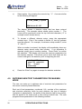
4.4. SELECTING A DETECTOR SETUP FOR MAX/MIN MODE
The control unit can store up to eighteen sets of max/min test parameters
for the min/max testing of the user’s most commonly tested detectors.
These can be recalled instantly from within the microprocessor's memory
when required. Each set of test parameters, numbered 1-18, consists of
data concerning the detector, including the maximum and minimum
sensitivity acceptance limits stored for that detector.
Before running a max/min test, a make/model of detector needs to be
selected from one of the 18 detector setups stored in memory. (If the
required detector has not been entered previously it can be entered into
the memory by the user, see section 4.5., Entering New Test Parameters
for Max/Min Mode.) The user selects the required detector setup as
follows:
a)
Using the "Test mode" key on the keypad , select max/min testing.
b)
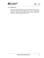
If the required detector is not already displayed, press the “Set-up”
key on the keypad. (Step (a) may be omitted if the user wishes to
enter setup directly from the default screen). The following menu
will be displayed:
1.Recall Setup
2.Change Setup
3.Number of Tests
__________________________________________________________________
OPERATING INSTRUCTIONS
25
Issue:
2.1e
Trutest User Manual
Date: 01/12/08
___________________________________________________________________
c)
Select option 1 by pressing the numeric key "1". A screen similar
to the following will appear:
01: NO_NAME_01 photo
Which one 01-18?
The display shows a detector setup that has been entered
previously. The example above shows setup number 1. The
cursor will be positioned under the top left-hand character (“0” in
example screen shown above).
d)
To choose a different detector setup, press the appropriate
numeric keys. Even if the number is below 10, two key presses
must be entered. For example, for detector setup number 5, enter
“0”, then “5”.
When a number is entered, the display will immediately show any
detector setup stored under that number. If an alternative is
required, simply type in another number. Press “Enter” to confirm
the selection. The display will show the max/min parameters for
the detector selected. This allows you to check that these are the
correct settings for the detector, prior to beginning the test:
05: NO_NAME_05
min=1.00 max=2.00
ion
lo prof’
slow ramp
e)
Press the “Enter” key again to accept the detector selection.
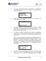
4.5. ENTERING NEW TEST PARAMETERS FOR MAX/MIN
MODE
The user can enter up to eighteen sets of max/min test parameters for
their most commonly tested detectors.
Each set of test parameters, numbered 1-18, consists of the maximum
and minimum sensitivity limits for each detector, the type of detector
(ionization or photoelectric), the profile of the detector (high or low profile),
and the speed of the ramp (slow or fast) during max/min test. The user
programs these parameters in the following manner:
___________________________________________________________________
26
OPERATING INSTRUCTIONS
Issue:
2.1e
Trutest User Manual
Date: 01/12/08
__________________________________________________________________
a)
From any of the default screens, (see Section 4.1., Preparing to
Test) press the 'Set-up' key on the keypad. The following menu
screen will appear:
1.Recall Setup
2.Change Setup
3.Number of Tests
b)
Select option 2 by pressing the number "2" on the keypad. The
following screen will appear:
01: NO_NAME_01 photo
Which one 01-18?
c)
The display shows a detector setup that has been entered
previously. The example above shows setup number 1. The
cursor will be positioned under the top left-hand character (“0” in
example screen shown above).
d)
To choose a different detector setup, press the appropriate
numeric keys. Even if the number is below 10, two key presses
must be entered. For example, for detector setup number 6, enter
“0”, then “6”.
When a number is entered, the display will immediately show any
detector name/description already stored under that number. If an
alternative is required, simply type in another number. Press
“Enter” to confirm that you wish to enter/modify the parameters of
this selection. The display will show the max/min parameters for
the detector selected, with a cursor, “→”, to prepare for entry or
modification:
06: →NO_NAME_06
min=1.00 max=2.00
ion
lo prof’
slow ramp exit
e)
Position the cursor at the field(s) that needs to have new data
entered. The cursor is moved about the screen using the keypad
‘arrow’ keys: “2”, “4”, “6”, and “8” representing “down”, “left”, “right”
__________________________________________________________________
OPERATING INSTRUCTIONS
27
Issue:
2.1e
Trutest User Manual
Date: 01/12/08
___________________________________________________________________
and “up” respectively. Press “Enter” to modify or enter data in that
field.
f)
With the cursor positioned adjacent to the detector name field,
pressing the “Enter” key reveals the following screen:
06: NO_NAME_06
^
ABCDEFGHIJKLM01234 NOPQRSTUVWXYZ56789
._
A new cursor, “^”, shows beneath the first character of the detector
name. New characters can be used in this name/description by
changing each one in turn.
g)
To change the character with the “^” cursor beneath it, move the
flashing block cursor (using the ‘arrow’ keys as above) to the
desired character in the list shown in the lower half of the screen.
To accept the currently shown choice of character, press “Enter”.
After the final character has been accepted, the user is returned to
the setup screen to continue with other parameter entry.
h)
For the “min” or “max” fields, simply enter the new values from the
keypad. If a value outside the full-scale capability of Trutest is
entered, and the “exit” option from the setup screen is chosen, a
continuous warning beep of five seconds will sound, and the cursor
will be returned to the offending value for alteration. For details of
the full-scale values, see section 8.1., Technical Specifications.
i)
For the detector type field (ionization or photoelectric), the “Enter”
key toggles between “ion” and “photo”. Since the full-scale
obscuration values for photoelectric and ionization tests are
different, a value for the “max” field which is acceptable for tests on
photoelectric detectors, may not be acceptable should the detector
type be later changed to ionization. In this case, when the “exit”
option from the setup screen is chosen, a continuous warning beep
of five seconds will sound, and the cursor will be returned to the
offending value for alteration. For details of the full-scale values,
see section 8.1., Technical Specifications.
j)
For the detector profile field (high or low profile), the “Enter” key
toggles between “hi prof’” and “lo prof’”.
___________________________________________________________________
28
OPERATING INSTRUCTIONS
Issue:
2.1e
Trutest User Manual
Date: 01/12/08
__________________________________________________________________
k)
For the ramp speed field (slow ramp or fast ramp), the “Enter” key
toggles between “slow ramp” and “fast ramp”.
l)
When all parameters have been entered/modified as required,
move the cursor to the “exit” field and press “Enter”. Trutest saves
all the changes and returns to the screen, which was displayed
prior to entering setup. If Trutest is turned off prior to this, any
modifications or changes to the parameters will not be saved.
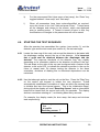
4.6. STARTING THE TEST SEQUENCE
After the operator has assembled the system (see section 3), set the
detector type and the test mode (see section 4), the test can begin.
4.6.1 Locate the clear cup of the main unit around the detector to be tested with
the diaphragm sealing around the top of the detector. It is important
that a good seal be obtained between the diaphragm and the
detector. The response threshold of the detector may vary slightly
depending on its orientation relative to the direction of airflow in the cup.
The red stripe on the side of the cup can be aligned with a feature of the
detector, such as its LED, to indicate the detector’s position in the cup for
future or repeat tests. By always testing the detector in the same
orientation, variations of reading due to directional dependence can be
minimized.
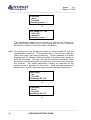
4.6.2 Use the telescopic poles to rest the unit on the floor. Press the "Start" key
on the control unit keypad to initiate the test sequence. Trutest
automatically establishes a circulation of clean air within the sensing loop
to initialize and zero the internal sensor. This is the initialization stage,
during which the display will read "Resetting Sensor" and an intermittent
beep will be heard from the control unit every five seconds. The display
shows a countdown starting at 7, and lasting about thirty seconds.
For example, the display reads (for slow ramp, fast ramp and min/max
tests respectively):
Slow ramp
ion
hi profile
Resetting sensor 7
or
__________________________________________________________________
OPERATING INSTRUCTIONS
29
Issue:
2.1e
Trutest User Manual
Date: 01/12/08
___________________________________________________________________
Fast ramp
photo
hi profile
Resetting sensor 7
or
NO_NAME_01 ion
min=1.00
max=2.00
Resetting sensor 7
This ‘initialization stage’ can be carried out without the Trutest cup
positioned over the detector e.g. when moving from one test to another,
but must be in place for the test to begin (see below).
4.6.3 On completion of the initialization stage the smoke sensitivity test will
automatically commence. The selected type of test will be conducted
(either slow ramp, fast ramp or max/min). Trutest maintains a constant
airspeed past the detector while a carefully controlled smoke density is
gradually increased. The user will hear the solenoid mechanism pulse
the aerosol canister, along with a double beep from the control unit every
five seconds. The smoke obscuration reading as measured by the
internal sensor is displayed on the screen. Some example screens are
shown below, for slow ramp, fast ramp and min/max tests respectively:
Slow ramp
ion
hi profile
Reading=0.98 %/ft
or
Fast ramp
photo
hi profile
Reading=1.80 %/ft
or
___________________________________________________________________
30
OPERATING INSTRUCTIONS
Issue:
2.1e
Trutest User Manual
Date: 01/12/08
__________________________________________________________________
NO_NAME_01 ion
min=1.00
max=2.00
Reading=0.62 %/ft
4.6.4 At this point the user is simply a witness as Trutest performs the test.
He/she should watch the detector to ensure that the diaphragm is sealed
around the top and wait for the LED of the detector to activate when the
detector reaches its alarm level. The audible intermittent beep from the
control unit assures the user that a test is in operation.
4.7. THE END OF THE TEST
4.7.1 When the detector activates, and the detector Alarm LED lights, press the
"Stop" key on the control unit keypad to finish the test. The user will then
be presented with the appropriate result screen (see section 5.6.,
Interpretation of Results).
4.7.2 The test sequence will stop automatically if the detector has not activated
(i.e. the "Stop" key has not been pressed) by the time the equipment
reaches the full-scale obscuration limit (see section 8.1., Technical
Specifications). The result screen should then be checked for the exact
reason for the end of the test (see section 5.5., Interpretation of Results).
4.7.3 In all cases, once the test has completed, Trutest unit will rapidly establish
a circulation of clean air within the sensing loop to clear the detector and
the Trutest Unit (see section 4.8.2).
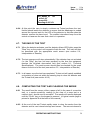
4.8. COMPLETING THE TEST AND CLEARING THE SMOKE
4.8.1 The result from the screen; either a pass or fail (in the case of a max/min
test), or a smoke sensitivity reading (in the case of a ramp test or a
max/min test), should now be recorded. The results will remain displayed
until the "Enter" key on the keypad is pressed. (A typical results page is
printed in Appendix B at the back of this manual).
4.8.2 At the end of the test Trutest rapidly starts to clear the smoke from the
detector and its own internal airways and sensor. The amount cleared is
__________________________________________________________________
OPERATING INSTRUCTIONS
31
Issue:
2.1e
Trutest User Manual
Date: 01/12/08
___________________________________________________________________
shown on the result screen. When the "Enter" key is pressed, the display
returns to the default screen, still showing the amount of smoke cleared
from the internal sensing loop. For example (max/min screen):
NO_NAME_01 ion
min=1.00
max=2.00
Clearing smoke 80%
4.8.3 The clearing cycle has two stages:
Stage 1 - Detector clearing (0 - 49%)
It is recommended that the user keeps the detector within the plastic cup
during this stage. This will clear any aerosol from the smoke detector so
that it will not re-alarm when the fire alarm system is reset. Note
however, that there will be very little aerosol to clear since the test will
have been stopped as soon as the detector has activated (i.e. at the
absolute minimum concentration required to activate an alarm).
Stage 2 - Removal of Trutest (50 - 100%)
When Trutest has reached 50% clear the user will be prompted to
"Remove Trutest" and a rapid double beep is heard. It is advisable to
withdraw the unit from the detector at this time, as that will help to clear
the smoke from the sensing loop more rapidly.
NOTE:
Leaving Trutest in position over the detector during this
stage will increase the clearing time.
Do not switch off Trutest until all of the smoke clearing stages have
completed. The smoke clearing cycle will last between thirty seconds and
3 minutes depending on the concentration of aerosol to clear.
4.8.4 The test is now complete. If another detector is to be tested, the user can
go immediately to it and start the next test. However, do not cover the
new detector until the smoke clearing stage is complete, and the display
shows: "Press Start to test" (see section 7.1. Questions on Usage for a tip
on speeding up testing).
If no further testing is required, use the "On/Off" key on the keypad to
switch off the control unit and conserve power.
___________________________________________________________________
32
OPERATING INSTRUCTIONS
Issue:
2.1e
Trutest User Manual
Date: 01/12/08
__________________________________________________________________
5.
RESULTS
5.1. GENERAL OBJECTIVE OF RESULTS
Trutest has been designed to perform on-site sensitivity tests on all
makes of smoke detector. The sensitivity of a detector may be defined as
the density (concentration) of smoke required to trigger an alarm. Testing
with Trutest should enable the user to identify:
a)
The ability of the detector to respond to the presence of a predefined external smoke stimulus. Much time can be saved since
the detector does not need to be removed from its base, tested,
replaced and then re-tested for function within the system.
b)
The ability of the installed detector to communicate with the panel
and raise an alarm.
c)
Those detectors which may be outside acceptable sensitivity limits.
These can then be cleaned or replaced.
d)
Any drift in sensitivity of conventional detectors (similar to the
function of analogue detectors but with Trutest a true external
stimulus is used) and to take corrective action.
5.2. RESULTS SCREEN FOR RAMP TEST
5.2.1 At the point that the "Stop" key is pressed and the test stopped, the final
level of obscuration is displayed. This figure may then be compared with
the minimum and maximum acceptable levels specified by the detector
manufacturer, or may be noted for future comparisons.
5.2.2 The obscuration figure is in %/ft, corresponding to the minimum level of
smoke required to activate the detector.
Result:
Reading=1.85 %/ft
Press Enter
__________________________________________________________________
RESULTS
33
Issue:
2.1e
Trutest User Manual
Date: 01/12/08
___________________________________________________________________
5.2.3 If the obscuration level reaches the maximum level attainable (see section
8., Technical Specifications) and the detector has not alarmed, the test
will stop automatically and the message “Full scale” will replace the
“Result” field on the screen. For example, the following screen shows a
ramp test which reached a maximum attainable obscuration value of
6.00%/ft:
Result:
Full scale=6.00 %/ft
Press Enter
If the Trutest main unit or the aerosol canister is below its standard
operating temperature range (i.e. below 50°F (10°C)), the unit may not be
able to reach the normal full-scale range. This can also be caused by a
faulty aerosol nozzle. However, the display will still report a full-scale
reading at the point at which it stopped, even though this may be below
the normal maximum. The reading displayed will be the maximum
obscuration obtained during the test.
5.3. RESULTS SCREEN FOR MAX/MIN TEST
With the max/min test, Trutest provides a pass or fail result, depending on
whether the detector alarmed within or outside the pre-programmed
acceptance band. The actual sensitivity reading is shown, and the final
result is also displayed as a pass or fail. In some cases, there can be an
indeterminate outcome from the max/min test, and this will be displayed
also.
5.3.1 If the detector LED is seen to illuminate (the detector activates) before the
“min” value is reached, and the key is pressed to stop the test, the results
display will read (for an alarm level of 0.6%/ft in this example):
Result:
Failed oversensitive
Reading=0.60 %/ft
Press Enter
5.3.2 If the detector LED is seen to illuminate (the detector activates) between
the “min” level and the “max” level, and the key is pushed to stop the test,
the results display will read (for an alarm level of 2.3%/ft in this example):
___________________________________________________________________
34
RESULTS
Issue:
2.1e
Trutest User Manual
Date: 01/12/08
__________________________________________________________________
Result:
Detector passed
Reading=2.30 %/ft
Press Enter
5.3.3 If the detector LED does not illuminate (the detector does not activate) by
the “max” level, and the key is pushed to stop the test, the results display
will read (for an alarm level of 3.1%/ft in this example):
Result:
Failed insensitive
Reading=3.10 %/ft
Press Enter
5.3.4 If the detector LED does not illuminate (the detector does not activate)
and the maximum attainable obscuration level is reached (full scale) prior
to the “max” level in the max/min test, the test will stop automatically.
Since it is not known whether the detector would have alarmed at a higher
level, but still below the “max” level, an indeterminate result is displayed.
For example, the following screen shows a max/min test which reached a
maximum attainable obscuration value of 5.35%/ft, but the “max” value
entered for the detector was 5.50%/ft:
Result:
Indeterminate Result
Full scale=5.35 %/ft
Press Enter
See section 5.2.3 for details of the “Full scale” condition when this occurs
at a level below the maximum values specified in section 8.
5.4. WARNINGS SHOWN ON RESULT SCREENS
Any of three warning messages may be communicated to the user on the
result screens. In place of the first line, and in addition to the results and
other parameters on the result screens, there may be one of the following
warning messages, which the user must heed (shown in order of priority):
a)
b)
c)
Service due soon!
Battery voltage low!
Sensor drifted!
Each of these messages is described in Section 6.4., Warning Messages.
__________________________________________________________________
RESULTS
35
Issue:
2.1e
Trutest User Manual
Date: 01/12/08
___________________________________________________________________
Should more than one of these messages be relevant at the time of a result
screen display, only the highest priority warning will be shown.
A two-second warning beep will accompany any of these warning messages to
alert the user.
A typical result screen with a warning message may look like this (example
shows a max/min result screen with a pass result):
Service due soon!
Detector passed
Reading=2.30 %/ft
Press Enter
5.5. STORED RESULTS
The unit will store results of the last two tests until the power is turned off.
a)
If the user requires reference to a previous test result press the left
arrow key ("4"). The following is an example of a result screen
which would be displayed (this example shows a ramp test result):
Result:
Reading=1.85 %/ft
Press Enter
b)
If the result of the second last test is required, press the left arrow
key ("4") again. The following is an example of a result screen
which would be displayed (this example shows a passed max/min
test result):
Previous Result:
Detector passed
Reading=2.61 %/ft
Press Enter
Pressing the left arrow key ("4") repeatedly will toggle back and forth
between the two result screens shown in (a) and (b) above.
___________________________________________________________________
36
RESULTS
Issue:
2.1e
Trutest User Manual
Date: 01/12/08
__________________________________________________________________
5.6. INTERPRETATION OF RESULTS
IMPORTANT - READ CAREFULLY
It should be noted when using Trutest, that there are a large number of
factors affecting the sensitivity readings, which should only be judged
within the conditions and limits quoted in the Technical Specifications.
Detector sensitivity readings can change depending on the orientation of
the detector, environmental conditions, wind conditions, differences
between Trutest units and aerosol canisters, and the repeatability of the
detector.
These systematic and random uncertainties which relate to Trutest are
generally covered within the figures quoted in the Technical
Specifications. Note also that repeated tests on the same detector, can
result in inaccurate readings, if the test aerosol is not given sufficient time
to clear totally from the detector. Depending on the detector concerned,
this could take as long as five minutes, although in practice, the clearing
cycle will stop after about two to three minutes.
All sensitivity results displayed should generally be compared with those
values provided by the manufacturer as acceptable for that detector in the
field, but also taking into account any uncertainties in the measurement.
The manufacturer’s values should be printed on the base of the detector,
or in the data sheets. Trutest measurement uncertainties are shown in
section 8.1., Trutest Specifications. Should any results fall outside of the
acceptance parameters, the detector may be considered to be over or
under sensitive.
It should be noted that figures from one manufacturer of detectors should
not be compared with figures from another manufacturer in an effort to
determine superiority of one detector over another. Any conclusions
drawn in this manner would be at best subjective and misleading.
Where specific results are not available for a particular model of detector,
the user may take a sample number of readings from similar detectors
installed on their site, and by statistical means, establish a nominal
acceptance band. This is described in more depth in Appendix C.
Further, by recording the results of "Ramp Tests" over time on a given
detector it is possible to track any drift of that detector.
__________________________________________________________________
RESULTS
37
Issue:
2.1e
Trutest User Manual
Date: 01/12/08
___________________________________________________________________
5.7. ACTION IF A DETECTOR FAILS A TEST WITH TRUTEST
If a detector fails a sensitivity test, there are steps you should take prior to
condemning it.
1.
2.
3.
4.
5.
Ensure that the aerosol canister in Trutest is not nearly empty.
This can easily be determined by shaking the canister and listening
for any remaining liquid. If it is nearly empty, replace it with a new
canister before proceeding.
Ensure that there has been a good seal between the detector and
the silicon membrane during the test.
Ensure that you have entered the correct details of the detector
into Trutest e.g. ionization/ photoelectric and lo/hi profile.
The detector should be retested. Be sure to allow adequate smoke
clearing time between tests.
Also be sure to allow for all measurement uncertainties in your
sensitivity acceptance thresholds before condemning detectors.
See section 8.1. Trutest Specifications for details of the
measurement uncertainties in Trutest. Other uncertainties may
exist within the system also e.g. delayed alarm response of
detectors, which will be more apparent on fast ramp readings.
Should the detector fail on retest, taking all the above into account, then
the detector can be assumed to be out of tolerance.
The detector should now be replaced with another one of the same type
and model, and the replacement one should be tested. Note that some
detector manufacturers allow for cleaning of their detectors, in which case
the faulty detector should be cleaned on site, or returned for cleaning.
Please refer to the respective manufacturer for information on cleaning or
replacing detectors.
If a detector is returned for servicing, it is
recommended to mark the final Trutest reading on the detector, including
the calculated uncertainty in the measurement.
___________________________________________________________________
38
RESULTS
Issue:
2.1e
Trutest User Manual
Date: 01/12/08
__________________________________________________________________
6.
SERVICE AND MAINTENANCE
Trutest is a high quality electronic test instrument and as such, regular
calibration and servicing as well as care in use are essential. Regular
calibration ensures reliability, and continuing accuracy in use. It is
recommended that this product be returned to an authorized service
center annually. After 5,000 tests the unit will automatically shut down
until it has been serviced.
6.1. USER SERVICING
Little user servicing should be necessary and the user should not attempt
to service this equipment beyond that described in this manual. All other
servicing should be referred to qualified service personnel at authorized
service centers.
6.1.1. Cleaning
From time to time you should wipe the equipment with a soft cloth. For
heavier dirt, dampen a soft cloth in a weak solution of mild detergent and
water, wring it dry, and wipe off the dirt. Following this, dry immediately
with a clean cloth. Do not use rough materials, thinners, alcohol or other
chemical solvents or cloths since these could damage the finish or
remove the equipment labels. Only qualified service personnel should
perform cleaning of the internal parts.
6.1.2. Damage Requiring Servicing
This equipment should be serviced (by qualified service personnel) when:
a)
Objects have fallen or liquid has been spilled into the equipment.
b)
The equipment has been exposed to rain.
c)
The equipment does not appear to operate normally or exhibits a
marked change in performance.
d)
The equipment has been dropped or the enclosures damaged.
__________________________________________________________________
SERVICE AND MAINTENANCE
39
Issue:
2.1e
Trutest User Manual
Date: 01/12/08
___________________________________________________________________
6.1.3. Replacing the Fuse
The fuse holder is located on the side of the control unit and is clearly
labeled. Never replace the fuse with any other type / rating than that
recommended in the specifications. To replace the fuse, use a flat bladed
screwdriver to undo the screw cap, replace the fuse with an identical
replacement and refit. If the fuse repeatedly blows, return the ENTIRE
Trutest kit for servicing.
6.1.4. User Calibration Check
Trutest has been factory calibrated and tested. There is no reason to
believe that there will be any shift in calibration or accuracy, since the
sensor is self-monitoring and self-adjusting. If the sensor is damaged the
unit will shut down and will not perform tests. However if the user wishes
to be sure of the calibration of the unit over an ongoing period, the
following is recommended:
a)
Take two detectors of factory quality: one ionization and one
photoelectric.
b)
Test these detectors with Trutest and record the results. Use all
modes of test.
c)
Keep the detectors in a safe, dry, dust-free environment.
d)
After a period of using Trutest, test the detectors again, recording
the results. Should the difference be greater than the expected
Trutest repeatability PLUS the repeatability of the detector, then it
may be necessary to have Trutest re-calibrated.
Note: No attempt should be made to open Trutest.
Entry and
subsequent servicing is permitted only by an authorized service
center.
6.1.5. Membrane Condition Check
The condition of the membranes used to seal the Trutest cup to the
detector should be checked periodically. Should there be any damage to
these membrane seals, results could be affected. Replacements should
be obtained from your Trutest supplier in this case.
___________________________________________________________________
40
SERVICE AND MAINTENANCE
Issue:
2.1e
Trutest User Manual
Date: 01/12/08
__________________________________________________________________
6.2. ANNUAL SERVICING
In order to maintain the accuracy and performance from this instrument, it
is recommended that Trutest be returned to an authorized service center
for an annual service and re-calibration. This should be performed
annually or after 5,000 tests, whichever is the sooner.
However, Trutest monitors the number of tests performed and announces
to the user when calibration is due. Once the test limit of 5,000 tests has
been exceeded Trutest will not permit further use without re-calibration
and will need to be returned to an authorized service center. A charge
will be made for this service.
The number of tests performed, and how many remain before obligatory
service, can be determined by referring to the Service Screen on the
control unit. The product may also have to be returned to a Service
Center if other problems occur (see section 6.4., Warning Messages and
section 6.5., Troubleshooting Guide).
Overseas customers should
confirm with the supplier when purchasing where the closest authorized
service center is located.
6.3. SERVICE SCREEN
The user can determine the number of tests Trutest has performed since
the last service via the Service Screen as follows:
a)
From any of the default screens, (see section 4.1., Preparing to
Test) press the 'Set-up' key on the keypad. The following menu
screen will appear:
1.Recall Setup
2.Change Setup
3.Number of Tests
b)
Select option 3 by pressing the numeric key "3". The number of
tests performed and the number of tests remaining before service
are displayed on the service screen as follows:
Tests=4000
To service=1000
Press Enter
c)
Press 'Enter' to return to the original default screen.
__________________________________________________________________
SERVICE AND MAINTENANCE
41
Issue:
2.1e
Trutest User Manual
Date: 01/12/08
___________________________________________________________________
6.4. WARNING MESSAGES
The following warning messages are generally preceded by a two-second
continuous beep from the control unit.
6.4.1. Low Battery
6.4.1.1
When the NiCd Battery is drained almost completely, the Low
Battery Warning message is displayed. If the condition arises
during a test, the message will appear on the result screen, but will
not interfere with the test. For example:
Battery voltage low!
Reading=1.05 %/ft
Press Enter
At this time, Trutest is able to complete approximately 12 more
tests, or one hour of testing. It should then be recharged before
further use.
6.4.1.2
When the battery is completely drained, (after approximately 12
more tests or one hour of testing), a further battery warning will
appear during the initialization stage:
Warning!
Battery voltage low!
Press Enter
After this warning, the display will return to the start screen, but will
not allow any further tests to be performed.
6.4.2. Service Warnings
Trutest automatically monitors the number of tests it has performed in
order to provide warning when calibration is imminent. Trutest will permit
5,000 tests before automatic shut down.
___________________________________________________________________
42
SERVICE AND MAINTENANCE
Issue:
2.1e
Trutest User Manual
Date: 01/12/08
__________________________________________________________________
6.4.2.1
A warning message will occur when the number of tests remaining
before service goes below 250. The message appears on the
result screen, for example:
Service due soon!
Detector passed
Reading=1.97 %/ft
Press Enter
The user can determine exactly how far away he/she is from an
obligatory service by interrogating the control unit (see section 6.3.,
Service Screen).
6.4.2.2
When the 5,000 test limit is finally reached Trutest will
automatically shut down when the "Start" key is pressed and will
not permit any further tests. Instead, the following message will be
displayed:
Warning!
Service due NOW!
Press Enter
6.4.3. Empty Aerosol Can
If the aerosol concentration starts to drop rapidly during a test, the aerosol
canister probably needs replacing, and the following message will be
displayed:
Warning!
Can empty!
Press Enter
At this stage, a new aerosol canister should be fitted, and the test
restarted (see section 3.4., Fitting the Aerosol Canister).
__________________________________________________________________
SERVICE AND MAINTENANCE
43
Issue:
2.1e
Trutest User Manual
Date: 01/12/08
___________________________________________________________________
6.4.4. Sensor Drift
If the following message appears on a result screen:
Sensor drifted!
Detector passed
Reading=2.64 %/ft
Press Enter
this means that the sensor may be dirty, blocked or misaligned. The
results may be unreliable and care should be taken with their
interpretation. The unit should be returned to an authorized service
center for servicing and re-calibration.
6.4.5. Wiring Fault
If the following screen appears:
Warning!
Head not fitted!
Press Enter
the user should check whether the main unit is correctly connected to the
control unit. When everything has been checked, press the “Enter” key
and try the test again. This could indicate a fault with the interconnecting
lead, so try the other lead if the message persists. After this, if the
warning continues, it could indicate a fault with the sensor. In this case,
contact a service center.
6.4.6. System Error
If the following screen appears:
System error 0x
the user should press "on/off" on the control unit to reset the system. If it
re-appears the user should check the wiring and connections. If it
persists, the unit should be returned for service.
___________________________________________________________________
44
SERVICE AND MAINTENANCE
Issue:
2.1e
Trutest User Manual
Date: 01/12/08
__________________________________________________________________
6.4.7 Min/Max Error
Should the setup parameters for a min/max test be entered in such a
manner that the full-scale obscuration value of Trutest is exceeded for
that type of detector, Trutest alerts the user prior to saving setup
information. New data entry is prompted, thus ensuring that parameters
are within the normal operating range of Trutest.
__________________________________________________________________
SERVICE AND MAINTENANCE
45
Issue:
2.1e
Trutest User Manual
Date: 01/12/08
___________________________________________________________________
6.5. TROUBLESHOOTING GUIDE
The following problems do not require professional servicing. If the
problem cannot be remedied using this guide, contact your authorized
service center for assistance.
Problem
Possible Causes
Remedy
Blank screen, no
response from
on/off key.
Blown fuse.
Check and replace.
Flat Battery.
Recharge.
"Head not fitted"
warning.
Interconnecting cable not fitted
properly.
Check connections at both ends of cable.
No response from
main unit
Interconnecting cable not fitted
properly.
Check connections at both ends of cable.
Detectors do not
alarm.
Faulty detectors.
Check against known detector.
Wrong settings.
Check settings for correct "Det. type",
"Test mode" and "Setup".
The system has a leak.
Ensure detector is sealed within cup by
diaphragm.
Problems obtaining
high obscuration
Levels.
Check main unit for visible leaks. If found,
return the unit to an authorized service
center.
Check condition of diaphragms and
replace if damaged or broken.
No rise in
obscuration reading
on display.
Unstable reading
during ramps or
poor control.
Aerosol or room temperature
too low.
Check temperature is above 50°F on
gauge on main unit. Warm aerosol
canister slightly in heated office or car for
30 minutes. (Do not place on radiator or
fire).
No aerosol canister in main
unit.
Check and fit.
Empty aerosol canister.
Check and replace.
Dented aerosol canister.
Check and replace.
Aerosol canister incorrectly
loaded.
Check against instructions in manual.
Wrong main unit parameters
stored in the control unit.
Check that the serial numbers on the
control unit and main unit match.
___________________________________________________________________
46
SERVICE AND MAINTENANCE
Issue:
2.1e
Trutest User Manual
Date: 01/12/08
__________________________________________________________________
7.
FREQUENTLY ASKED QUESTIONS
7.1. QUESTIONS ON USAGE
Q:
Does Trutest suit all makes of smoke detector?
A:
Yes, Trutest has been developed specifically to this end. It is used
normally to test against the maximum and minimum values printed on the
base of the detector, or in the manufacturers’ data sheets. However,
where manufacturers' figures are unavailable, a site can still be tested,
and individual detectors compared to the average values obtained for that
site. A method to produce these field values, is described in section C.1.
of the Appendices.
Q:
Is Trutest applicable to ‘self testing’ analogue systems?
A:
Analogue addressable and intelligent sensors can only monitor the
'clean air response' or normal quiescent response of the internal sensor.
This however does not test the actual alarm level, nor can it take into
account variations in atmospheric conditions (dust, air movement, etc.).
To determine the response of the sensors to smoke, they still need to be
tested periodically with a controlled and measured source of test aerosol.
By testing with Trutest can you be sure of the sensitivity to smoke and the
continuing accuracy of the sensor.
Q:
How long does a test take?
A:
The total time required for a sensitivity test varies according to the
type of test, the type of detector, and the sensitivity of the detector.
Trutest works by gradually increasing the smoke density presented to the
detector, therefore the more sensitive the detector, the quicker it will
respond. Generally however, a test will take between three and five
minutes, including the sensor initialization stage, and the final smoke
clearing. In addition, the time taken to get to the next detector, and to
position the Trutest unit should be added to give an overall idea of time.
A slower test will generally be a more accurate one since there are often
delays in the alarm circuitry of detectors and panels (see section 4.3.3).
TIP:
The smoke clearing stage generally takes between thirty seconds and
three minutes, and works faster if the main unit is removed from the
detector when indicated on the display. The operator can go on to the
next detector, and prepare Trutest for the next test, while waiting for the
smoke clearing stage to finish. Even the next initialization can be started
whilst 'on the move' between tests, provided that Trutest is located over
the detector in time for the test to start.
__________________________________________________________________
FREQUENTLY ASKED QUESTIONS
47
Issue:
2.1e
Trutest User Manual
Date: 01/12/08
___________________________________________________________________
7.2. QUESTIONS ON SENSITIVITY & CALIBRATION
Q:
How do I know that Trutest will give accurate results?
A:
Trutest has been tested at Underwriters Laboratories in the United
States, where it has been given a generic listing as an accessory for
automatic fire detection systems. The readings on Trutest’s LCD are
correlated directly to the UL smoke box. Note that readings should
always be interpreted correctly in the light of the specification of Trutest
and the detector under test. See section 5.6., Interpretation of Results for
more details.
Q:
Is Trutest’s UL listing good for all makes of detector?
A:
Trutest has a generic UL listing, which means that it is listed to
work with any make of detector.
Q:
How will I know that Trutest is correctly calibrated at the start
of a test?
A:
Trutest is fully self-adjusting and re-calibrates itself at the start of a
test. It therefore automatically takes account of any contamination within
the system and adjusts to compensate for it. If this is a concern the user
can perform his own tests with a detector of known quality at given
intervals to prove this. (See section 6.1.4. User Calibration Check).
Q:
What is the time interval between services?
A:
As Trutest is a high precision test tool, periodic workshop
verification and re-calibration will be necessary. To meet international
quality standards, a service is required at least once per year, or every
5,000 tests, whichever occurs earlier. The sensor is programmed to "auto
shut down" after 5,000 tests or if a problem is detected, and will give a
warning before that. See Section 6.2 Annual Servicing.
Q:
What happens when the sensor is unable to self-calibrate?
A:
Trutest will no longer give results and the LCD will display a
message to this effect (indicating a fault with the sensor). At this point the
unit will need to be returned for service.
Q:
Can the user make adjustments?
A:
The only user adjustments are made from the front panel e.g. for
detector setup parameters and test selections. There are no user
adjustments within the main unit or the control unit.
___________________________________________________________________
48
FREQUENTLY ASKED QUESTIONS
Issue:
2.1e
Trutest User Manual
Date: 01/12/08
__________________________________________________________________
7.3. QUESTIONS ON EFFECTS OF TEMPERATURE &
HUMIDITY
Q:
What is the effect of temperature on performance:
A:
Extensive tests have been carried out to determine the effect of
temperature on the performance of Trutest. As Trutest uses a liquefied
gas aerosol canister, the critical operating temperatures are determined
by the gas characteristics. The maximum operating temperature is limited
to 95°F, as the maximum storage temperature for the aerosol canister is
120°F in line with international safety requirements.
The lower temperatures are, however, far more critical for the
performance of the Trutest. If the aerosol canister temperature is too low,
the internal pressure drops rapidly and produces too many large particles.
This is normally seen when Trutest cannot reach the maximum
obscuration level shown in the specifications, but shows a full-scale
reading at a lower level. The specified minimum operating temperature of
50°F, is very critical. At this temperature, the performance starts to
rapidly drop off, and could affect the detector readings. Always check the
room temperature as shown on the indicator strip on the side of the main
unit, and ensure that the aerosol canister is at, or above, this temperature
when testing.
Note that the action of spraying the aerosol canister causes internal
cooling.
Therefore the more testing is performed, the lower the
temperature drops in the main unit and aerosol canister.
TIP:
Keep a spare Trutest aerosol canister in a warm (i.e. room temperature)
place (e.g. in an office). When the temperature in the aerosol canister
drops below 50°F (10ºC), exchange it with the warm canister. Also allow
a slightly longer time than usual for recovery between tests. This will
allow the main unit to recover to the ambient room temperature.
Q:
What effect does relative humidity have?
A:
The particles of aerosol smoke used within Trutest, as with all
smoke particles, are affected by very high levels of relative humidity. At
high levels of humidity, where the air is saturated with water, the smoke or
aerosol particles act as nuclei for small droplets of water to form. These
are not seen as easily by the smoke detectors, and can give a false
sensitivity reading. Additionally, as the release of the high-pressure
contents from the aerosol canister has a cooling effect, the relative
humidity level is reduced further, so that water particles start to form.
TIP:
Relative humidity tends to be highest at sunset and sunrise in some
climates (this causes dew). If the sensitivity readings for a number of
detectors appear to be suspect in the early morning or late evening, it
could be caused by high humidity. Try retesting these detectors in the
middle of the day.
__________________________________________________________________
FREQUENTLY ASKED QUESTIONS
49
Issue:
2.1e
Trutest User Manual
Date: 01/12/08
___________________________________________________________________
7.4. QUESTIONS ON TRUTEST AEROSOL
Q:
How
consistent
and
repeatable
are
the
aerosol
characteristics?
A:
Very.
This is a function of the aerosol canister, chemical
formulation, valve and spray nozzle. All are subject to strict quality control
(as is the rest of Trutest).
Q:
What effect does "aging of smoke" produce?
A:
With ionization smoke detectors there are often concerns due to
'aging' of smoke. Tests were carried out in which a high concentration of
aerosol was maintained up to 120 seconds. The results showed that this
process did not affect the relative sensitivity of ionization detectors.
Q:
How many tests can the user get from a canister of aerosol?
A:
This will depend on the type of test that Trutest is asked to
perform, the design of the detector and the relative state of sensitivity of
the detector under test. An average of 100 tests per canister can be
expected.
Q:
What is in the aerosol canister?
A:
The Trutest aerosol uses a mixture of an "environmentally friendly",
non-flammable propellant gas liquefied at high pressure with non-toxic
active ingredients. It has been tested for compatibility with detectors and
users. For more details see the aerosol health and safety data sheet
supplied with the product. Note that being a pressurized container, it will
need sensible handling and be subject to certain transport regulations.
Always follow the instructions on the canister.
Q:
Can the Trutest aerosol smoke be ignited?
A:
The Trutest aerosol is not classed as flammable by the Federal
Hazardous Substances Act, which determines the correct level of
classification and labeling for aerosol goods in the USA. However, since
almost anything can burn if sufficient energy is deployed, it is possible to
ignite the spray under very severe conditions. These conditions have
been investigated and have been confirmed by UL not to exist either in
Trutest nor in its operating environment. As an analogy of this situation,
consider a housebrick, which although it burns under certain conditions, is
virtually impossible to ignite with a match.
___________________________________________________________________
50
FREQUENTLY ASKED QUESTIONS
Issue:
2.1e
Trutest User Manual
Date: 01/12/08
__________________________________________________________________
Q:
Can any other smoke aerosol canister be used in the device?
A:
No. The tool is designed to use only the special Trutest aerosol
canisters, and a different product would not work or give correct results.
Other formulations could cause serious damage to both the detector
under test and Trutest.
Q:
Why do ionization detectors require a greater concentration of
aerosol to activate?
A:
The particle size distribution of the aerosol, has a relatively higher
concentration of larger particles recognized by photoelectric detectors
than ionization detectors. This is a deliberate design feature, as the
internal obscuration sensor is more sensitive to the larger particles
enabling more consistent measurements for both types of smoke
detectors.
7.5. QUESTIONS ON BATTERIES AND POWER
Q:
How long will one charge of the batteries last?
A:
This depends on many factors; different types of test consume
different amounts of power. In normal use the batteries last for 8-10
hours of continuous testing. If the tester is switched off whilst moving
from detector to detector, this will give at least one full day of testing. The
control unit display will prompt visibly and audibly if the batteries are low
and it can be recharged overnight. In general, for each hour of charging,
the unit will manage one hour of testing.
Q:
What would happen if the machine were accidentally left
switched on?
A:
The machine incorporates an automatic shut down after fifteen
minutes without use.
7.6. QUESTIONS ON USER INPUT / USER INTERFACE
Q:
How do I set the make and type of detector for each type of
test?
A:
No specific detector set-up is required for ramp mode, although
you do need to select the detector type (ionization, photoelectric, high or
low profile). Set-up data for the max/min mode is input via a menu
prompt system. The required information is detailed in section 4.4 of this
manual "Selecting a Detector Setup for Max/Min Mode"
__________________________________________________________________
FREQUENTLY ASKED QUESTIONS
51
Issue:
2.1e
Trutest User Manual
Date: 01/12/08
___________________________________________________________________
Q:
How does the user know what stage of the test cycle is
running?
A:
Either by looking at the message on the display or by hearing
different beeps from the control unit.
Q:
What memory has Trutest?
A:
The microprocessor has an internal memory for storing detector
settings. Some of this memory is the non-volatile EEPROM type, which
will retain information even with the power, is removed. It is used to:
•
•
•
store default settings;
store user programmed settings;
record information relevant to servicing.
7.7. QUESTIONS ON RESULTS AND DISPLAYS
Q:
Can the results be recorded?
A:
Only by hand. After a test has been completed the results are
displayed on the LCD until the "Enter" key is pushed. They can be
transferred manually to the results page that is found at the back of the
manual. The last two results are stored in volatile memory and can be
displayed by toggling the left arrow ("4") key.
7.8. QUESTIONS ON WEIGHT, INSULATION AND PRACTICAL
USAGE
Q:
What about the weight?
A:
Some parts of Trutest are relatively heavy. However, the control
unit is suspended on a shoulder strap and the SOLO Telescopic
Operating Pole permits the unit to be rested on the floor during testing.
This means that the weight of the main unit is never borne for long.
Q:
Is the unit electrically insulated (to save the operator from any
shock from live cables that may contact the device)?
A:
The SOLO Telescopic Operating Pole is made from insulating
composite materials to protect the user when accidentally touching high
voltage supplies. However the unit should not be viewed as being
completely non-conductive. Extreme care should be taken when working
near any electrical installations or overhead power lines.
___________________________________________________________________
52
FREQUENTLY ASKED QUESTIONS
Issue:
2.1e
Trutest User Manual
Date: 01/12/08
__________________________________________________________________
Q:
How do we cope with detectors fitted in situations where
Trutest can not reach or fit?
A:
The detectors which cannot be accessed can either be removed
from their bases and placed in more accessible bases (exchanging the
detectors) or powered up separately and tested.
Q
Can Trutest be used on detectors mounted on sloping ceilings
or which have to be accessed from an angle?
A:
To a very limited degree. If the aerosol canister is tipped too
much, it may not dispense the correct particle sizes. It may be better to
exchange with detectors in more accessible positions. You should always
ensure that the diaphragm seal properly seals the detector within the cup.
Q:
Will Trutest cope with deeper detectors (e.g.: older style or
those sitting on junction boxes)?
A:
Yes, so long as a seal can be achieved with the diaphragm. Note
that only the sensing chamber of the detector has to be sealed within the
cup.
__________________________________________________________________
FREQUENTLY ASKED QUESTIONS
53
Issue:
2.1e
Trutest User Manual
Date: 01/12/08
___________________________________________________________________
This page is intentionally blank
___________________________________________________________________
54
FREQUENTLY ASKED QUESTIONS
Issue:
2.1e
Trutest User Manual
Date: 01/12/08
__________________________________________________________________
8.
TECHNICAL SPECIFICATIONS
8.1. TRUTEST SPECIFICATIONS
Part No.
SOLO100
Component
Dimensions
Telescopic Operating Pole
Length (extended)
Length (not extended)
Weight
3lb 15oz
(1.80kg)
14ft 9ins
(4.50m)
4ft 2ins
(1.26m)
SOLO101
Extension Pole
44ins
(1.13m)
12oz
(0.35kg)
TRUT710
Extension Cable
8ft 2ins
(2.50m)
7oz
(0.19kg)
TRUT711
Extension Cable
16ft 4ins
(5.00m)
11oz
(0.32kg)
TRUT730
Height Adjustment Clamp
TRUT300
Main Unit (excluding aerosol)
8 x 4 x 29ins
(195 x 105 x 740mm)
5lb 13oz
(2.65kg)
TRUT351
Control Unit
7 x 3.5 x 4.5ins
(175 x 85 x 110mm)
3lb 8oz
(1.6 kg)
TRUT753
+
TRUT781/
2/3/4/5
Battery Charger (complete with
regional adapter)
3.5 x 2 x 1.3ins
(90 x 50 x 35mm)
6oz
(0.16 kg)
TRUT702
Gray Diaphragm Seal
Detectors dia. 3.7 - 5.7ins
2oz
(0.06kg)
TRUT703
Pink Diaphragm Seal
Detectors dia. 2.8 - 4.3ins
2oz
(0.06kg)
TRUT600
Trutest Carry Case
33.5 x 13.5 x 8.5ins
(850 x 345 x 210mm)
4lb 11oz
(2.12kg)
SOLO602
Carry bag for SOLO poles
50.0 x dia.4.0ins
13oz
(0.38kg)
TRUT771
User Manual (this document)
4oz
(0.12kg)
TRUT760
Spare Fuse Pack (3 per pack)
0.5oz
(0.01kg)
AERO400
Aerosol Canister
2oz
(0.06kg)
2.1ins dia. x 6.8ins
(52mm dia. x 177mm)
11oz
(0.31 kg)
__________________________________________________________________
TECHNICAL SPECIFICATIONS
55
Issue:
2.1e
Trutest User Manual
Date: 01/12/08
___________________________________________________________________
OPERATING DATA
Trutest uncertainties in sensitivity measurements: (Note: For correct
interpretation of results, the tolerance of the detector under test and any other
measurement uncertainties must also be taken into account). Specified at 68°F
+/- 5°F < 60% RH , using slow ramp.
All detector types and profiles
Operating Parameters:
Maximum Working Height:
Average Test Time:
Average Calibration Time:
Average Clearing Time:
Average Tests per Aerosol Canister:
Average Battery Life:
Test Stream flow rate:
Resolution:
Aerosol Concentration Range
Maximum for ionization:
Maximum for photoelectric:
Rate of Rise of Aerosol Concentration
Slow Ramp:
Fast Ramp:
± (10% of reading + 0.6 %/ft)
typically ± (10% of reading + 0.3
%/ft)
20ft 8ins (6.3m) (using SOLO100 +
SOLO101)
120 seconds
40 seconds
120 seconds
100 tests
8-10 hours testing on a full charge
0.6ft/s to 1.3ft/s (0.2 to 0.4m/sec)
0.01 %/ft
4.00 %/ft
6.00 %/ft
0.50 %/ft / minute
1.00 %/ft / minute
Type of Aerosol
See Section 8.2 and Safety Data Sheet
Environment:
Operating Temperature:
Storage Temperature:
Humidity:
50°F to 95°F (+10ºC to +35° C)
15°F to 120°F (-10ºC to +50° C)
(Do not store in direct sunlight)
0 - 85% RH non-condensing
Fuses
Fuse Rating
Fuse Style
1A Anti Surge
20 mm Glass Tube
Battery
Nominal Voltage:
Capacity:
Charger Nominal Voltage:
12VDC
2.5Ah
18VDC
___________________________________________________________________
56
TECHNICAL SPECIFICATIONS
Issue:
2.1e
Trutest User Manual
Date: 01/12/08
__________________________________________________________________
8.2. AEROSOL DATA
Description:
Part Number:
General Description:
AERO400
An environmentally friendly aerosol
canister for use with Trutest Smoke
Detector Sensitivity Tester.
Specifications:
Dimensions:
Pressure:
Material:
Contents:
Operating Temperature:
Storage Temperature:
Aerosol:
Propellant:
Physical Data:
Boiling Point:
Vapor Pressure:
-15.7°F (-26.5°C)
95lb/in2 (6.70kg/cm2) at 77°F
(25°C)
75lb/ft3 (1.20kg/dm3) at 77°F (25°C)
Colorless gas, liquid under pressure
Very faint ethereal odor
Liquid Density:
Appearance:
Odor:
Occupational Exposure Limit:
Gas:
General:
2.1ins (53mm) dia x 6.8ins (173mm)
18 bar maximum
Aluminum monobloc
9.5oz (270g)
approx. 8.5fl oz (250ml)
50°F to 95°F (+10ºC to +35° C)
15°F to 120°F (-10ºC to +50° C)
Blended Oxy-hydrocarbons
1,1,1,2 Tetrafluoroethane
1000ppm (3540mg/m3) (Long term
exposure limit – 8 hr TWA reference
period)
Very low acute toxicity; weak
anaesthetic
at
very
high
concentrations. Not mutagenic in
Ames test or CHO cell assay.
See No Climb Products Health and Safety Data Sheet MDS 0065 for more
details.
Fire / Hazard Class:
DoT Registration:
Not defined as flammable by
§1500.3 (c)(6), 16CFR, Federal
Hazardous
Substances
Act,
C.P.S.C.
Regulations,
USA.
HOWEVER, THE PRODUCT CAN
BE IGNITED UNDER CERTAIN
CIRCUMSTANCES. 20% by mass
of the contents are flammable.
DOT2Q, registration no. M5215
__________________________________________________________________
TECHNICAL SPECIFICATIONS
57
Issue:
2.1e
Trutest User Manual
Date: 01/12/08
___________________________________________________________________
UL Listing:
77TL
Smoke-Automatic
Fire
Detector Accessory. Generic listing.
Environmental Information:
Tetrafluoroethane is not currently
regulated under the Montreal Protocol
and may be used as a replacement for
regulated CFC's.
___________________________________________________________________
CAUTION
AEROSOL CANISTERS CAN BE HAZARDOUS.
Pressurized
containers can explode if correct method of storage and use is not
observed. Contents can be ignited under certain conditions.
When using/handling/storing the Trutest aerosol:
• Always follow the instructions on the canister. Failure to do so will
increase the risk of injury.
•
Read the Safety Data Sheet supplied with the product.
•
CONTENTS UNDER PRESSURE. Protect from direct sunlight and
do not expose to temperatures exceeding 120ºF (50ºC). Do not
pierce or burn, even after use.
•
Use in a well ventilated area. Avoid deliberate inhalation / Do not
breathe spray.
•
Avoid skin and eye contact.
•
KEEP OUT OF THE REACH OF CHILDREN.
•
The Trutest aerosol is not defined as flammable by §1500.3 (c)(6),
16CFR, Federal Hazardous Substances Act, C.P.S.C. Regulations,
USA. HOWEVER, THE PRODUCT CAN BE IGNITED UNDER
CERTAIN CIRCUMSTANCES. DO NOT SPRAY ON A NAKED
FLAME OR ANY INCANDESCENT MATERIAL.
•
Keep away from sources of ignition – No smoking.
•
20% by mass of the contents are flammable.
___________________________________________________________________
Note: In summer or on hot days extra care should be taken to protect from
sunlight and other high temperatures. Even the boot of a car can reach
excessive temperatures. If in doubt, an insulator / "Thermos" type bag
should be used to store cans.
___________________________________________________________________
58
TECHNICAL SPECIFICATIONS
Issue:
2.1e
Trutest User Manual
Date: 01/12/08
__________________________________________________________________
APPENDIX A - AUTHORIZED SERVICE CENTERS
A.1
UNITED KINGDOM
No Climb Products Limited
Edison House
163 Dixon’s Hill Road
Welham Green
Hertfordshire
AL9 7JE
UK
Telephone:
Facsimile:
Email:
Website:
A.2
+44 (0)1707 282760
+44 (0)1707 282777
[email protected]
www.detectortesters.com
UNITED STATES OF AMERICA
SDi
1345 Campus Parkway
Neptune
NJ 07753-6815
USA
Telephone:
Facsimile:
Email:
Website:
(732) 751 9266
(732) 751 9241
[email protected]
www.sdifire.com
__________________________________________________________________
APPENDICES
A1
Issue:
Date:
Trutest User Manual
2.1e
01/12/2008
APPENDIX B - RESULTS PAGE
Serial Number of Trutest Used_________________
Date of Tests_________ Sheet _____ of ______
Name of Test Engineer_____________ Name of Client __________________ Location (Site, Town, City, Country) _____________
Detector Tested
Location
Type of Test
Model, Type
Within site
Fast / Slow Ramp
or Max/Min
Result
Comments / observations
State of detector / Site conditions
Notes:
_____________________________________________________________________________________________________________
APPENDICES
B1
Issue:
2.1e
Trutest User Manual
Date: 01/12/08
__________________________________________________________________
APPENDIX C. - DETECTOR PERFORMANCE
TABLES
C.1.
Method for Producing Detector Performance Tables
If you cannot find the details for the particular type and model of detector
you wish to test, the following procedure should be followed:
1.
Test a representative sample of the same model and type (e.g. 6)
on slow ramp.
2.
Test all the detectors on the site (or on more than one site if you
have 20 or less of each type), and record the results.
3.
At this stage, you should already be able to spot the detectors
which are obviously out of norm, as they will be considerably
different from the average (up to two times higher, or 2/3 less than
the average values).
4.
Add up all the values for each model of detector, and divide by the
number of detectors to give an average or Mean value for that
model.
5.
To generate Minimum and Maximum values, a ratio between Min
and Max should be agreed. A typical figure for this could be 1:2.2.
To create a ratio of 1:2.2 of Min to Max, use the following formula:
Min = Mean x 0.625
Max = Mean x 1.375
6.
The Minimum and Maximum values can be used to check the
results already recorded, and can be programmed into Trutest as
explained in section 4.5 of the manual. The values chosen should
be recorded on a blank Detector Performance Sheet (see
Appendix C.2.).
__________________________________________________________________
APPENDICES
C1
Issue:
Date:
Trutest User Manual
C.2
Detector Performance Sheet
Site:__________________________________
1
Model
Manufacturer Ref. No.
1 Model
2 Max.
3 Min
4 Diaphragm
2.1e
01/12/08
Date: ___________________
System Type
Detector Type
Conventional /
Addressable
Photoelectric /
Ionization
2
Max.
3
Min.
4
Diaphragm
Pink or Gray
The manufacturer’s reference or model number for this detector.
The maximum sensitivity level for this detector model. The detector should have activated by this stage when tested with Trutest.
The minimum sensitivity level for this detector model. At this obscuration value, the detector should not activate when tested with Trutest.
The size of diaphragm seal to be used to seal this particular detector.
_____________________________________________________________________________________________________________
APPENDICES
C2