1
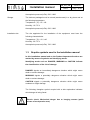
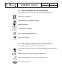
Installation manual MI_015_GB 13/12/13 Rev.0 Pag. 1 di 20 Installation manual for surgical light system TRIS-LED Ceiling Wall Mobile Installation manual Introduction MI_015_GB 13/12/13 Rev.0 Pag. 2 di 20 Dear user, You are kindly invited to read this manual carefully before proceeding to use the Product in order to safeguard yourself and other people from any injuries. Mark This appliance is a Class 1 medical device pursuant to European Directives on medical devices (MDD) 93/42/EEC, Annex IX, and 2007/47/EC. Conformity The manufacturer declares that this product is in compliance with Annex I (essential requirements of Directive 93/42/EEC and certifies such conformity by affixing the CE mark. The Product is classified in risk group 1 according to IEC 62471 standard (Photobiological Safety of Lamps). Validity of manual Customer service This operator’s manual refers to the following products: TRIS-LED single ceiling version TRIS-LED double ceiling version (TRIS-LED+TRIS-LED) TRIS-LED wall TRIS-LED mobile The customer service is at your disposal in case of Product details, information concerning its use, identification of spare parts being required and for any other queries you might have concerning the appliance, for ordering spares and for matters relating to assistance and warranty. Copyright RIMSA P.LONGONI SRL Via Monterosa 18 I-20831 Seregno MB Tel.: ++39 0362 325.709 Fax: ++39 0362 328.559 Email: [email protected] The contents of this Manual may be amended by Rimsa, without prior notice or any further obligations, in order to make changes and improvements. The reproduction, including partial, or translation of any part of this manual is forbidden without the written permission of RIMSA. Installation manual MI_015_GB 13/12/13 Rev.0 Pag. 3 di 20 Right to make changes Rimsa reserves the right to change, cancel or otherwise amend the data contained in this document at any time and for any reason without prior notice inasmuch as Rimsa is constantly seeking new solutions which lead to product evolution. Rimsa therefore reserves the right to make changes to the supplied Product in terms of shape, fittings, technology and performances. Translations With regard to translations into languages other than Italian, reference shall always be made to the Italian edition of this operator’s manual. Installation manual MI_015_GB 13/12/13 Rev.0 Pag. 4 di 20 Table of Contents 1 General information .................................................... 5 1.1 Qualification of operators .............................................................. 6 1.2 Packaging, transport, storage and characteristics of the installation site .............................................................................. 6 1.3 Graphic symbols used in the installation manual .......................... 7 1.4 Graphic symbols used on the package......................................... 8 1.5 Other graphic symbols used on the Product ................................. 8 1.6 Warranty Certificate ...................................................................... 9 2 Mechanical and electrical arrangement of the site . 10 2.1 Mechanical arrangement of the site............................................ 10 2.2 Electrical arrangement of the site ............................................... 13 3 Product installation ................................................... 13 3.1 Ceiling version (single and double) ............................................. 14 3.1.1 Ceiling plate installation ......................................................... 14 3.1.2 Installation horizontal arm to anchoring tube ......................... 14 3.1.3 Oscillating arm (just for double lamp) .................................... 15 3.1.4 Cupola installation (satellite option) ....................................... 15 3.2 Wall version installation ............................................................... 15 3.2.1 Wall plate installation ............................................................. 15 3.2.2 Horizontal arm installation ..................................................... 16 3.2.3 Cupola installation ................................................................. 16 3.3 Mobile version............................................................................. 16 3.3.1 Installing pipe on mobile base ............................................... 16 3.3.2 Installation of oscillating arm.................................................. 17 3.3.3 Cupola installation .................................................................. 17 3.4 Connecting to electrical plant...................................................... 18 3.5 First starting ................................................................................ 19 3.6 Installation verification and Product testing operations before use .................................................................................................... 19 Note ................................................................................................... 20 Installation manual MI_015_GB 13/12/13 Rev.0 Pag. 5 di 20 1 General information IMPORTANT Product The ME (Medical-Electrical) EQUIPMENT to which this manual refers is a LAMP for Operating Theatre or SYSTEM of LAMPS for Operating Theatre. For easier description such ME EQUIPMENT will be indicated in this manual with the name of “Product”. CAUTION This manual is an integral part of the Product as required by European directive 93/42/EEC and 2007/47/EC. Always keep this installation manual close to the lamp. CAUTION - The Product is not suitable for use in explosion-risk areas - The Product is not suitable for use in the presence of inflammable mixtures of anaesthetics with air, oxygen or NO2 (laughing gas) CAUTION RIMSA disclaims all liability for any injuries to persons or damage to things caused by the installation, maintenance or use of the Product by unqualified operators. By qualified operator is meant whosoever has attended a course relating to the installation, maintenance and use of the product organised by RIMSA or, alternatively, whosoever has carefully read this installation manual. CAUTION The only party responsible for Product installation is the buyer’s customer itself; no cost or responsibility relating to installation and/or commissioning of the Product shall therefore be traced back and/or in any case attributed to RIMSA. CAUTION The masonry works involving the preparation of the ceiling or wall, for Products to be installed on the ceiling or wall respectively, and the electric works for preparing the power supply system for the Product shall be of a sturdy and safe nature and completed in a workmanlike manner by suitably trained personnel. By way of example only, without limitation, the following professional figures are deemed adequately trained: Building Engineer, Draughtsman, Building firm duly registered in the professional Register (for masonry works) Electro-technician qualified to exercise the profession of electrician (for the electrical works) Installation manual CAUTION MI_015_GB 13/12/13 Rev.0 Pag. 6 di 20 Electrical installation must be made in compliance with the IEC 60364-7-710 standard and any national regulations and must contemplate protection with fuses or thermal magnetic disconnection switch and the fitting of a master switch able to ensure the complete interruption of the power supply to the Product. CAUTION The Product is a ME EQUIPMENT and consequently falls within the field of application of the EN:62353 standard. Consequently, any operation performed on the Product must be carried out in compliance with the EN:62353 standard, where applicable. 1.1 Operator qualification Qualification of operators This paragraph describes the requirements and qualifications which the operators involved in the various stages of Product life and use must possess. Installation the Product must be installed by a qualified Installer and/or Technician Use Professional medical personnel Routine maintenance Qualified technician in possession of professional technical requirements Special maintenance Qualified technician in possession of professional technical requirements Assistance Dealer who has attended a technical course on the Product organised by the manufacturer Cleaning Properly trained medical and paramedical personnel Demolition at the end of the Product life cycle, dispose of the used Product in an environment-friendly way and in compliance with the national directives applicable to waste disposal 1.2 Packaging, transport, storage and characteristics of the installation site Packaging Boxes containing the whole structure with installation instruction manual and user’s manual. Transport Transport is carried out by any road haulage contractor as long as they respect the following characteristics: Temperature (°C): -15 / +60 Humidity: 10 / 75 % Installation manual MI_015_GB 13/12/13 Rev.0 Pag. 7 di 20 Atmospheric pressure (h/Pa): 500 / 1060 Storage The devices packaged must be stored (warehoused) in a dry place and at the following temperature: Temperature (°C): -15 / +60 Humidity: 10 / 75 % Atmospheric pressure (h/Pa): 500 / 1060 Installation site The site appointed for the installation of the equipment must have the following characteristics: Temperature (°C): +10 / +40 Humidity: 30 / 75 % Atmospheric pressure (h/Pa): 700 / 1060 1.3 Graphic symbols used in the installation manual In this installation manual and on the Product important directions are marked by means of symbols and identifying words. Identifying words such as DANGER, WARNING or CAUTION indicate the classification of the risk of damage. DANGER signals an immediately dangerous situation which might cause death or serious damage. WARNING signals a potentially dangerous situation which might cause death or serious damage. CAUTION signals a potentially dangerous situation which might cause moderate or slight damage. The following triangular symbol coupled with a side explanation indicates which danger is being faced: Electric shock, Mechanical danger due to hanging masses (quick release of a suspension arm) Installation manual 1.4 MI_015_GB 13/12/13 Rev.0 Pag. 8 di 20 Graphic symbols used on the package The symbols present on the boxes of the packages are listed below: High side of the package Maximum number of packages stackable Breakable package Humidity-suffering package Do not overlap packages with pallet Weight of the package 1.5 Other graphic symbols used on the Product The symbols present on the Product are listed below: B-Type device. Indicates the level of protection against direct and indirect contact Graphic symbol proving the CE marking of the product Symbol indicating the manufacture date (month and year) Fuses used by the device Installation manual 1.6 MI_015_GB 13/12/13 Rev.0 Pag. 9 di 20 Warranty Certificate 1. The appliance is covered by an 18-month warranty, including electrical parts. 2. The warranty begins on the date of product shipment from the RIMSA warehouse to the buyer. 3. In case of disputes, the date indicated on the “transport document” attached to the goods shall be deemed valid. 4. The warranty only covers the sending of Product spare parts to the buyer or, in the event of RIMSA considering the replacement of spare parts not feasible, the replacement of the entire product, after fabrication faults have been properly ascertained at the undisputable judgement of RIMSA. The warranty does not therefore cover any other costs or expenses (including, by way of example but without limitation, labour costs, packaging costs and transport costs, etc.). 5. The guarantee does not include the components subject to normal wear, such as halogen bulbs, LEDs, fuses, relays, ball bearings, etc. 6. The warranty does not cover: - malfunctions due to failure to comply with the instruction manuals; - malfunctions due to installation and/or maintenance errors; - malfunctions or faults caused by carelessness, negligence, incorrect use or other causes not attributable to RIMSA; - malfunctions or faults due to the fact that the electrical system of the premises where the machine is installed is not in compliance with International or local standards for electrical systems in premises used for medical purposes and similar standards. 7. RIMSA shall repay direct damages suffered by the buyer and which are documented as attributable to its product, caused within the warranty period, for an amount not above 40% of the net value of the product as indicated on the buyer’s invoice. RIMSA’s liability is expressly ruled out for indirect damages or consequential damages (including cases of the lamp not being used) deriving from the supply. 8. This warranty certificate replaces legal warranties for faults and non-conformities and rules out any other possible liability of RIMSA originating from the supplied products. 9. The payment of any damages to persons or things due to product malfunction or faults shall be limited to the maximum amount of RIMSA’s insurance coverage for civil liability. 10. The warranty shall be automatically invalidated in the event of: - the product having been tampered with or modified by the buyer or third parties; - the product having been repaired by the buyer or third parties, without following the instructions in the instruction manuals; - the product serial number having been cancelled, defaced or removed; - the buyer not being up to date with payments. 11. For jobs to be done under warranty, the buyer shall contact RIMSA only. Installation manual MI_015_GB 13/12/13 Rev.0 Pag. 10 di 20 12. The component parts replaced under warranty must only be returned to RIMSA, if so requested by RIMSA, carriage free and suitably packed. 13. In case of failure to return a part requested by RIMSA, the cost of the component part will be charged. 14. RIMSA cannot accept returns from end users or in any case from parties other than the buyer. 15. Products returned to RIMSA must be complete with documentation authorising such return and another document describing the malfunction. 16. For everything not indicated on this warranty certificate, reference shall be made to the laws of Italy. 17. For all disputes deriving from or related to the orders to which this warranty certificate applies and which cannot be amicably settled between the parties, the only competent law court shall be that of Milan. 2 Mechanical and electrical arrangement of the site NOTE The building and electrical arrangement works for the installation of the product are the responsibility of the Final Customer. 2.1 DANGER Mechanical arrangement of the site The building slab arrangement works to install the product must be carried out in a solid and safe way according to the standards by qualified personnel. By qualified personnel we mean, including but not limited to, the following professionals: Building Engineer, Surveyor, Building Contractor, duly registered with the Professional Register. DANGER In case of improper drilling, e.g. drilling of a piece of iron of the reinforced concrete, the technician responsible for the construction will have to be informed for safety reasons, since the statics of the premises might be compromised. CAUTION The ceiling must have a capacity of at least 300 Kg/m2 and a thickness of at least 250 mm. The installation site must be declared fit for use. Installation manual MI_015_GB 13/12/13 Rev.0 Pag. 11 di 20 After making sure that the site used as medical premises complies with the requisites required above, proceed to the mechanical anchorage of the ceiling plate determining the type of ceiling for the anchorage and acting accordingly. The installer assumes all responsibility, technical, civil and legal, related to the correct and suitable arrangement of the anchorage and installation of the Product, which must be carried out according to the standards. Fixing positions The Product is supplied complete with anchoring tube (tiges). Its length varies in relation to the height of the premises in which the Product is to be installed. The tiges is calculated to install the Product at a finished height from the floor to the cupola of the Product with the oscillating arm in a horizontal position of about 190/200 cm, save a different request from the client. As a non-exhaustive example, we list some of the types of slab: Reinforced concrete Mechanical anchorage: fix the ceiling/wall plate by means of 6 screw anchors Hilti HSL-3-G M16/25 (M6/12 for wall version) following the directions given by the insert manufacturer scrupulously and listed below for information: do (mm) t (mm) hs (mm) l (mm) Mt (Nm) SW (mm) x (mm) HSL-3-G M 16/25 24 125 100 163 80 24 25 HSL-3-G M 6/12 12 60 45 50 10 10 10 Anchor tie-rod do Nominal diameter of the point Mt t Minimum depth of drilling Sw Opening of the spanner hs Minimum depth of insertion l Length of anchor tie-rods x Closing torsion moment Fixing height Installation manual MI_015_GB 13/12/13 Rev.0 Pag. 12 di 20 1. Using the paper template attached to this manual, mark all the 6 fixing holes of the chosen point of the ceiling. 2. Make the first hole according to the safety anchor diameter. 3. By means of a pump or vacuum cleaner with pipe terminal, remove the dust and the small drilling fragments from the hole. 4. The anchor tie-rod must be inserted into the hole keeping it to axis and using a hammer. Attention! Consider the insertion depth. 5. By the hexagonal dynamometrical spanner tighten with spanner adjusted at the value specified by the constructor of the anchors, opening the anchor. The anchor tie-rod will immediately take the weight. 6. Make the remaining 5 holes and insert the anchor tie-rods as in previous points 2– 5. 7. After one hour, tighten the anchor tie-rods again with the tightening torque prescribed. Chemical anchorage: fix the anchoring tube with 6 chemical injection anchors mod. Hilti HIT-HY 150 with HAS following the directions given by the manufacturer Hilti scrupulously. After arranging the chemical anchors to the CEILING/WALL, fix the anchoring tube with nuts and lock nuts for each tie-rod and tightening with the hexagonal dynamometrical spanner you will tighten with spanner adjusted at the value specified by the constructor of the anchors. Clay-cement mix In this case it is compulsory to enclose the slab sandwich-like by the Product plate and the counter-plate. Installation manual MI_015_GB 13/12/13 Rev.0 Pag. 13 di 20 Plate and counter-plate must be enclosed to each other with M16 (M6 for wall version) steel threaded bars each, blocked at the upper and lower ends by respective washers, nuts and lock nuts. 2.2 DANGER Electrical arrangement of the site The electrical system arrangement works of the site used as medical premises to power the Product must be carried out in a safe way according to the standards by qualified personnel. By qualified personnel we mean, including but not limited to, the following professionals: Electro-technician licensed to practise as electrician DANGER Before installing the Product check the following conditions: the electrical system of the installation site must comply with the national laws and/or regulations in force for electrical systems in sites used as medical premises; the electrical system must be certified by an electrician licensed to issue the conformity certificate; the verification of the grounding circuit must be certified as required by the norms in force. 3 Product installation Before installing the Product, make sure that all the packages are present and in good condition, without any transport-related damage, and that the contents correspond to what is specified above. Claims will be considered only if the seller or the forwarder are informed immediately. Each claim must be in writing. Goods are always carried at the buyer’s risk. Keep the original package in case the lamp must be sent back. Installation manual 3.1 3.1.1 CAUTION MI_015_GB 13/12/13 Rev.0 Pag. 14 di 20 Ceiling version (single and double) Ceiling plate installation Incorrect levelling of the plate might cause the horizontal arm of the Product to make an unwanted move when passing from the non-balance condition to the balance one. See drawing 13 Place the sheet template (drawing 12) (2) to the ceiling (1) fixing it with adhesive tape (3). Run the following 6 holes as prescribed in paragraph 2.1 See drawing 14 After making the holes (3) to the ceiling (1), set the plate (2) to the ceiling through the use of bolts (4) by always using the spirit-level (5). See drawing 127 Make sure the power wires to the Product (1) reach the frame of the lamp power without creating interference with the anchoring tube. Insert the electrical panel (2) on the Tiges tube and anchor it by tight the two M6x16 DIN912 screws (3) and relative serrated washers (4). Place the electrical panel so that the slot (5) of the clamping frame corresponds with the M6 threaded hole (6) of the anchoring tube. Then, secure the electrical panel to the tube by tight the M6x16 DIN912 screw (7) and relative serrated washer (8). If you need to fix the electrical panel to another location along the anchoring tube, place it at the desired position and anchor it by tight the two M6x16 DIN912 screws (3) and relative serrated washers (4); with a Ø5 drill (9), make an hole on the anchoring tube in correspondence of the slot of electrical panel clamping frame and, with an M6 tap (10), thread the hole itself. Finally, secure the electrical panel to the tube by tight the M6x16 DIN912 screw (7) and relative serrated washer (8). CAUTION Depending on the type of ceiling (with false ceiling or less), place first the flat cover (11) or high (12). If the cover is in two pieces, you can install it later, but remember to previously insert the silicone ring (13) of the ceiling cover before to proceed with the installation of the lamp structure. 3.1.2 See drawing 112 Installation horizontal arm to anchoring tube Align the pivot of the horizontal arm structure (1) with the anchoring tube (2). Insert the power cables (3) along the tube and bring them out from the hole for the connection to the source. Installation manual MI_015_GB 13/12/13 Rev.0 Pag. 15 di 20 Insert the pin into the tube up to combine the 3+3 holes at 120° of the flanges with the 3 +3 holes at 120° of the pipe. Point to all 6 screws DIN7991 with hexagonal key N.3 Screw tightly ONLY two screws in a vertical side with each other (4) Then complete the remaining tightening. This will prevent loosening over time during the continuous rotation of the Product. 3.1.3 See drawing 113 Oscillating arm (just for double lamp) Align the oscillating arm pin (1) with the tube of horizontal arm (2). After connecting the plugs of the electric cables (3) with (4) among each other, insert the pin of the oscillating arm into the pipe of the horizontal arm and fix it by tight the three screws M5x12 DIN7991 (5) by use of hexagon key (6) N3. To help the insertion of connectors pull the cables from the slot located on the top of the arm. Make a “S” bend to the cables and close they inside the tube using the bent plate (7). Close it screwing the two screws (8). 3.1.4 See drawing 150 Cupola installation (satellite option) Align the pin of the cupola fork (2) with the tube of oscillating arm (1) and connect the terminals of the electric cables (3) with (4) among each other. Insert the pin of the fork into the pipe of the arm making correspond the respective 3 fixing holes and screw the three screws M4x8 DIN7991 (5). Fix the fork to oscillating arm, positioning upwards the hole (6) that houses the friction regulating dowel. In case of double lamp with satellite, install it following the steps above. 3.2 3.2.1 CAUTION Wall version installation Wall plate installation Incorrect levelling of the plate might cause the horizontal arm of the Product to make an unwanted move when passing from the non-balance condition to the balance one. See drawing 1 By means of a spirit-level (4) position the template sheet (drawing 11) (2) on the wall (1) fixing it with adhesive tape (3). Make the 6 holes following what is specified in paragraph 2.1 Installation manual See drawing 2 MI_015_GB 13/12/13 Rev.0 Pag. 16 di 20 After making the holes (3) on the wall (1), fix the plate (2) to the wall by means of bolts (4) always using the spirit-level (5). Make sure that the power supply socket (6) of the Product can reach a power supply point of the room without creating interferences with the movements of the same and the operators. 3.2.2 See drawing 3 Horizontal arm installation Align the arm (1) with the pin of the box (2). Then connect the terminals of the electric cables (3) with (4) among each other, respecting the polarity. See drawing 4 Insert the arm into the pin so as to make the 3 holes at 120° of the arm fit with the 3 holes of the pin ring nut. Screw in, one at a time, the 3 screws M5x12 DIN7991 (1) using a 3 Allen key (2). CAUTION Tighten the clutch (3) using a screwdriver (4) taking care to maintain the clutch well aligned with the threaded hole of the tube, so that this will screw without forcing. Rotate the slot of the screw clockwise to increase the friction effect and anticlockwise to reduce it. 3.2.3 See drawing 150 Cupola installation SEE POINT 3.1.4 3.3 Mobile version 3.3.1 Installing pipe on mobile base See drawing 148 Remove the bolt (2) and washer (3) from the stand bottom (1). Mechanical connection Position the stand (1) on the base (4) fitting and inserting its pawl (5) into the plate seat (6), use the bolt and washer previously unscrewed to join the stand to the base and tighten thoroughly. Insert the cover (7) from the stand top and the relevant connecting clip (8). WARNING – Instability and falling danger Failure to insert the detent into the appropriate seat present on the basement plate implies the risk of instability and the possible fall of the structure. Installation manual MI_015_GB 13/12/13 Rev.0 Pag. 17 di 20 Joint 3-poles connector of the stem and 6-poles connector of the switch to the related connectors located on the electrical panel. Then re-position base cover and ring and fix it tightening M4 screw located in the electrical board base. 3.3.2 See drawing 149 Installation of oscillating arm Align the pivot (2) of the oscillating arm with the hole of the tube (1) and join the electrical connectors (3) with (4) respecting the colours of the electrical cables. Insert the pivot (2) of the arm into the hole of the stem (1) until you are able to align the hole (5) of the screw M6x45 DIN912 with the hole (6) of the pivot. Screw down the screw (7) with a mechanical key and act on screw (8) to regulate the semi-rotation. Place the cover (9) as showed and lock it screw down the screw (10) with a hexagon key of n.2. 3.3.3 Cupola installation See drawing 150 SEE POINT 3.1.4 Installation manual 3.4 MI_015_GB 13/12/13 Rev.0 Pag. 18 di 20 Connecting to electrical plant DANGER – Danger of electric shock Before carrying out the electrical connections, check that the power line is NOT under tension in order to proceed with the montage safely. The group of the Product power (support plate, transformer, terminal block) as explained above, is designed to be fixed on the anchoring tube (for the ceiling version) or it is located inside wall box (for wall version) or enclosed inside mobile base cover (for mobile version). For ceiling version, to connect the line (F, N, T) to the cables of the Product (+,-, T) follow as written in the specific circuit diagram attached and as indicated from the labels placed on the electrical panel itself; in the case of mobile version, connect electrical cable with three pins from bent tube to base and electrical cable with six pins from cover to base, then you just need to connect the power cable plug to the network line; in the case of wall version you only need to connect the power cable plug to network line. . CAUTION – Irreparable damage to the Product Fuse protection at the terminals of the electrical panel must be insert ONLY AFTER you have made all the mechanical and electrical assembly of the Product. Any listing early can cause irreparable damage to the source of light. For long periods of non-use of the product to remove the fuses. Fuses FOR MODEL TRIS-LED: n°2 T1A (primary) and n°1 T6,3A (secondary) for 230Vac supply n°2 T2A (primary) and n°1 T6,3A (secondary) for 100Vac supply FOR MODEL TRIS-LED+TRIS-LED: n°4 T1A (primary) and n°2 T6,3A (secondary) for 230Vac supply n°4 T2A (primary) and n°2 T6,3A (secondary) for 100Vac supply FOR MODEL TRIS-LED BATTERY: n°2 T2A (primary) and n°1 T10A (secondary) for 230Vac supply n°4 T4A (primary) and n°2 T6,3A (secondary) for 100Vac supply Installation manual 3.5 CAUTION MI_015_GB 13/12/13 Rev.0 Pag. 19 di 20 First starting It is now possible to power the Product to check its starting with light emission. To do so, it is necessary to: 1 – close the circuit through the network switch upstream of the wiring (charged to the customer) 2 – put on ‘I’ position the bipolar switch of the floor base cover and on the wall box (only on mobile and wall versions) 3– press the I/O keyboard on the side of the fork 3.6 Installation verification and Product testing operations before use CAUTION The following notes are to be considered compulsory during verification of the installation, since they prove the correct verification of all the points set out. For such reason it is necessary to tick each point when it is treated. 1. Verify the suitability of the ceiling/wall on installation of the Product 2. By means of a spirit-level, verify the perpendicularity of the anchoring tube/wall plate 3. Put medium thread delay Loctite 243 on the six screws that fix the Product to the anchoring tube and check the tightness as instructed. 4. Check the cupola light emission glass. If the light emission glass is damaged or broken, glass splinters may fall. The Product must be turned off immediately and no longer used until the failure is removed. 5. Make sure that the movement mechanics work properly. Check the mechanical working of the Product through direction and rotation movements. 6. After starting, the Product must give light from the cupola Seal and signature of the installer: _____________________________________________________________ Installation manual Note MI_015_GB 13/12/13 Rev.0 Pag. 20 di 20 1 3 4 3 2 3 Drawing code Rev. Data 13 3 1 4 2 5 Tube external diameter: Ø80 n°6 x Ø18 holes 00 n3 n2 70 Drawing code Rev. Data 14 1 3 A 4 2 A B 7 B 8 3 12 6 5 C 11 13 C 7 5 9 10 8 Drawing code Rev. Data 127 15 2 3 1 4 Drawing code Rev. Data 112 2 A 1 A 3 4 6 5 Drawing code Rev. Data 113 A 5 2 1 4 3 A 6 B B Drawing code Rev. Data 150 4 1700 mm 2 3 1 Drawing code Rev. Data 1 3 4 2 1 5 6 Drawing code Rev. Data 2 1 3 4 2 Drawing code Rev. Data 3 3 4 1 2 Drawing code Rev. Data 1 03/03/2010 4 7 1 8 3 2 5 6 1 4 4 9 10 2 Drawing code Rev. Data 148