1
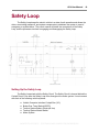
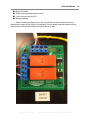
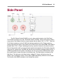
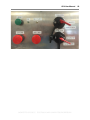
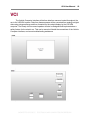
GLV User Manual 1 Abstract This user manual is a high level document that explains all operational procedures and techniques needed to operate the GLV system in a safe and effective manner. Anyone operating the GLV system should be familiar with this document, and this document should be referred back to in the event of a problem with the system. This document is broken up by GLV subsystem, and each section contains an introduction, instructions on getting started, and an operational procedure. The operational procedure will include a detailed explanation of all functions and controls, user level troubleshooting, calibration, and maintenance. Revision 2.0.0 GLV Team LAFAYETTE COLLEGE │ ELECTRICAL AND COMPUTER ENGINEERING GLV User Manual 2 Table of Contents Abstract Table of Contents Document Introduction User Breakdown Driver Pit Crew System Integrator Cockpit Panel GLV Hub GLV Power Setting Up the Power System GLV Power Operational Procedures Troubleshooting the Power System TSI Setting up the TSI External Components of the TSI Normal TSI Use Troubleshooting the TSI Safety Loop Setting Up the Safety Loop Engaging the Safety Loop Opening the Safety Loop After Opening the Safety Loop Side Panel VCI Setting Up the VCI Box Normal VCI Operation Troubleshooting LAFAYETTE COLLEGE │ ELECTRICAL AND COMPUTER ENGINEERING GLV User Manual 3 Document Introduction This document will outline how to set up all of the subsystems of the GLV system and how each system will work if it is properly functioning. The specific subsystems included in this document are the Power Box, TSI Box, VCI Box, and the safety loop. It also lists some basic troubleshooting methods for simple errors within the system. For issues that cannot be resolved from this manual, please reference the GLV maintenance manual. LAFAYETTE COLLEGE │ ELECTRICAL AND COMPUTER ENGINEERING GLV User Manual 4 User Breakdown Driver The only piece of equipment in the GLV system that the driver uses is the Cockpit Panel. Please see the Cockpit Panel normal operation subsection and the VSCADA user manual for help using the panel and its GUIs. Pit Crew The crew will have access to all vehicle components, though some may require some minor disassembly for access. The crew is responsible for problem diagnosis and will have access to each BRB for emergencies. System Integrator The system integrator will be responsible for all components within the GLV system. LAFAYETTE COLLEGE │ ELECTRICAL AND COMPUTER ENGINEERING GLV User Manual 5 Cockpit Panel Material List and Description: ● Aluminum Panel mounting platform ● Cockpit Reset Button (CPR) second method for driver reset ● Cockpit BRB emergency stop for driver ● Red ‘ Safety’ LED indicates that the system has shutdown ● Amber ‘Warning’ LED indicates a problem within the system ● Green ‘OK’ LED indicates full normal functionality in the Safety Loop ● Amber Indicator LED ● Ready To Drive Key ignition system for the car once all prior start protocol has taken place LAFAYETTE COLLEGE │ ELECTRICAL AND COMPUTER ENGINEERING GLV User Manual 6 LAFAYETTE COLLEGE │ ELECTRICAL AND COMPUTER ENGINEERING GLV User Manual 7 GLV Hub LAFAYETTE COLLEGE │ ELECTRICAL AND COMPUTER ENGINEERING GLV User Manual 8 LAFAYETTE COLLEGE │ ELECTRICAL AND COMPUTER ENGINEERING GLV User Manual 9 LAFAYETTE COLLEGE │ ELECTRICAL AND COMPUTER ENGINEERING GLV User Manual 10 GLV Power The GLV Power subsystem provides power to all of the nontractive systems in the electric vehicle. This includes the rest of the GLV subsystem, TSV AIRS, and VSCADA computer. The Power subsystem consists of a Power Box, which houses the battery, a DCtoDC converter, and a PCB. This Power Box has a Charging Port, four LEDS, GLV24B output, and GLVPD output. The function of all of these will be explained in the following sections. Explanations for important buttons and switches on the Side Panel of the car will also be provided. Power Box Panels LAFAYETTE COLLEGE │ ELECTRICAL AND COMPUTER ENGINEERING GLV User Manual 11 Setting Up the Power System The GLV Power System is located in the rear of the car with the Motor System and TSI. The GLV Power System supplies power to the rest of the vehicle, but starting the Power System is dependent upon the Side Panel, Safety Loop, and Charging Port. In order for the user to activate the Power System, the Side Big Red Buttons (BRBs) must be closed and the GLV battery must have sufficient charge. If these criteria are met, then the user will use the GLV Master Switch (GLVMS) to activate the entire system. When the GLV battery is supplying power to the system, the GLV24 LED on the Side Panel will be active. This light can be found on the front face of the Power Box as a Green LED next to the Charge Port. The two physical connections to the other parts of the vehicle are the GLV 24V Line and the Power and Data Line. These connections are located on the rear face of the Power Box.The GLV24 port is a 3Pin Molex that must be connected to the Side Panel. The GLVPD is a 9Pin DSub that must be connected to P4 of the GLV Hub. There is also a setup procedure for the charger of the GLV battery. The charger is made up of a 24vdc Power Supply, 6’ AC North American Cord, and a two wire cable with a 4Pin Square Molex connector on one end. The following are the steps for setting up the GLV charger. 1. Attach the green wire of the 6’ AC North American Cord to the middle screw of the Power Supply (Ground). 2. Attach the blue wire of the 6’ AC North American Cord to the second screw of the Power Supply (Neutral). 3. Attach the brown wire of the 6’ AC North American Cord to the leftmost screw of the Power Supply (Live). 4. Attach the black wire of the charging cable to the fourth screw of the Power Supply (DC Output ). 5. Attach the red wire of the charging cable to the rightmost screw of the Power Supply (DC Output +). GLV Power Operational Procedures The GLVMS is the Pit Crew’s on/off switch for the GLV Power System. All battery current flows through this switch; when deactivated, the GLVMS will disable power to all electrical circuits and electrical controls. The GLVMS is a red, rotary switch located on the Side Panel. The GLVMS is located next to the TSV Master Switch (TSVMS), which is discussed in Safety Loop section. Each Master Switch is clearly marked with the letters “GLV” or “TSV”. There is a GLV24 light located next to the GLVMS that indicates whether the GLV Power system is actively powering the vehicle. LAFAYETTE COLLEGE │ ELECTRICAL AND COMPUTER ENGINEERING GLV User Manual 12 Also located on the Side Panel are the Side BRBs. Each BRB is labelled either “Left” or “Right” indicating where they would be located on the electric vehicle. Each of these buttons will be a red pushrotate switch that separates the GLV battery from the rest of the GLV power lines.The BRBs will also kill the Accumulator Isolation Relays (AIRS). If a BRB is activated and the system is shutdown, the user must reset the BRB and then press the overall Reset to restore the state of the Safety Loop. The Reset button is located on the Side Panel. There is also a BRB reachable by the driver in the cockpit. The function of this BRB is detailed in the Cockpit Box section. The GLV battery is made up of 8 3.3V, 10Ah, LiF eP o 4 Battery Pack. The battery will be located in the Power Box which is in the rear of the car. It is here that the user can find the Charging Port, which is a 4Pin Square Molex clearly labelled with “Charging Port”. A 24vdc Power Supply will be used to charge the battery. This power supply will deliver a 2.2A current to the Power Box. There are also two LEDs located on the front face of the Power Box that indicate levels of charge. The charging process is as follows: 1. Plug the charger into the 120VAC wall socket. 2. Plug the 4Pin Square Molex into the Charge Port on the Power Box. 3. The yellow “Charging” LED will activate when the charger is properly connected and the battery is charging. 4. When the battery is fully charged, the green “Charged” LED will activate. 5. Remove the charger from the Charge Port and the 120VAC wall socket. According to the estimation Charging time (hours) = 1.2 x battery capacity (Ah) / 2.2, the 10Ah battery will take ~5.45 hours to charge. The Power Box also contains a DCtoDC converter which protects the battery from short circuit, overload, and overvoltage. There is a Charge Monitor located between the Charge Port, battery leads, and DCtoDC converter. This Charge Monitor is a PCB that also includes circuitry for data collection which will be sent to the VSCADA computer. There are also two more LEDs on the Power Box, next to the charging LEDs and the Charge Port. One indicates overtemperature, and the other indicates undervoltage. Troubleshooting the Power System If the GLV Power System is active, the battery is supplying power to the lowvoltage systems on the vehicle, and the GLV24 LED will be on. If this light is ever off and the user desires the system to be active, the following steps should be taken. 1. Check the GLV Master Switch on the Side Panel. If the switch is vertical, then it is off. Push and rotate the switch clockwise ninety degrees so that it remains horizontal. LAFAYETTE COLLEGE │ ELECTRICAL AND COMPUTER ENGINEERING GLV User Manual 13 2. Check the Side BRBs on the Side Panel. If a BRB is pushed in, the Shutdown Circuit is active. Rotate the deactivated BRB clockwise until it “pops” out of the off position. 3. Check the Undervoltage LED on the Power Box. If this light is active, the user should charge the battery according to the charging protocol listed in the previous section. 4. Check the Overtemp LED on the Power Box. If this light is active, the user should turn of the GLVMS and determine why the battery is overheating. 5. If none of these solves the problem, there is a more serious issue present. Turn off the GLV Power system at the Master Switch and consult an expert LAFAYETTE COLLEGE │ ELECTRICAL AND COMPUTER ENGINEERING GLV User Manual 14 TSI The load controller serves as a high voltage interface between the TSV battery packs and the motor controller. The isolation relay acts as a final switch in the high voltage line. The VSCADA system controls a precharge circuit which safely provides current to the motor controller. The isolation monitoring device is used to monitor galvanic isolation between the high and low voltage components and it will trip the safety loop whenever the IMD detects a fault. The TSI also contains TSVP lamp which turns on whenever there is greater than 18V across the high voltage ports. There is a voltage measuring system which measures the voltage across the battery packs. Setting up the TSI In this section we outline the steps that should be taken when setting up and connecting the load controller. These steps should be executed in the order that they are listed. 1. 2. SL IN: The safety loop in should be connected into the safety loop (see the Safety Loop section of this document). The four pin socket connector that is used is a TE 3507801 and should be connected using a TE 3507791. SL Out: LAFAYETTE COLLEGE │ ELECTRICAL AND COMPUTER ENGINEERING GLV User Manual 15 The safety loop out should be connected into the safety loop (see the Safety Loop section of this document). The four pin socket connector that is used is a TE 3507801 and should be connected using a TE 3507791. 3. 4. 5. 6. 7. 8. GLVPD: The grounded low voltage power and data bus must be connected to the GLV power box. This connection provides the power for the low voltage circuits in the load controller as well as a connection to the CAN data line. The six pin connector mounted on the load controller is a Mouser 57114807050 and should be connected using a Mouser 57114807040. GLV24: The GLV24 cable supplies the TSI with 24V from the GLV power box. The GLV24 connector mounted on the TSI is a two pin female Mouser connector and the cable used to connect to is a two pin male Mouser connector. HV+: High voltage plus is the positive high voltage line from the TSV battery pack. The other side of this cable must be a power lock connection to the positive side of the battery pack. Load+: Load plus is the positive high voltage line out of the load controller. The Load+ terminal will be connected directly the motor controller via screw and nut connection. Voltage will only be present if the isolation relay is closed. HV: High voltage minus is the negative high voltage line into the load controller. The Other side of this wire should be a power lock connection the pack. Load: Load minus is the negative high voltage line out of the load controller. The Load terminal will be connected directly the motor controller via screw and nut connection. Voltage will only be present if the isolation relay is closed. External Components of the TSI In this section we list and describe the external signals and components that are used by the TSI box. We describe how the signals should be interpreted and how the components should be used. 1. TSVP: LAFAYETTE COLLEGE │ ELECTRICAL AND COMPUTER ENGINEERING GLV User Manual 16 Tractive system active light is the red LED indicator. It turns on when the tractive system is active. This is defined as whenever there is 18V or greater outside the accumulator isolation relays. 2. 3. 4. GLV GMP: Ground low voltage ground measuring point is a banana jack connection directly to the low voltage system ground. This measuring point is required by the specifications and can be used in conjunction with the TSMP to create a ground fault error. TSMP+: Tractive system measuring point plus is a banana jack connection directly to the positive high voltage line. This measuring point is required by the specifications and can be used in conjunction with the TSMP to measure voltage across the high voltage system. TSMP: Tractive system measuring point minus is a banana jack connection directly to the negative high voltage line. This measuring point is required by the specifications and can be used in conjunction with the TSMP+ to measure voltage across the high voltage system. It can also be used in conjunction with the GLV GMP to create a ground fault. Normal TSI Use In typical operation for discharging, the system will start up when GLV 24 is provided. At this point the Safety Loop will be open as well as the AIRs (accumulator isolation relays), so there will be no high voltage present in the TSI. When the safety loop is closed, the AIRs close and high voltage is now present at the HV+ terminal of the load controller. Since the AIRs are closed the TSVP light will turn on provied there is greater than 18V across all the packs. When the user is ready to drive, the user must press the drive button on the SCADA interface. This will start the precharge circuit. If it the Safety Loop was tripped by a fault detection in the IMD, then the IMD Indicator LED int he cockpit will turn on. Under normal shutdown procedures, the drive would not be able to reset the error from within the car. During shutdown the Safety Loop will open and the red LED should turn off. If any indication happens other than this normal use case, there may be an issue and the user is advised to consult an expert. Troubleshooting the TSI Any errors in the TSI need the consultation of an expert and reference to the maintenance manual. Issues to look out for are the following: 1. If any plastic connectors on the outside of the box break or get pushed into the box, refer to the maintenance manual. LAFAYETTE COLLEGE │ ELECTRICAL AND COMPUTER ENGINEERING GLV User Manual 17 2. If any smoke is seen coming from the load controller or if the box has gotten unusually hot (>40 degrees Celsius), refer to the maintenance manual. 3. If it has been noticed that the isolation monitoring device has been constantly tripping or if a test has shown that it does not trip (indicated by the status of the of the safety loop), consult the maintenance manual. LAFAYETTE COLLEGE │ ELECTRICAL AND COMPUTER ENGINEERING GLV User Manual 18 Safety Loop The Safety Loop keeps the electric vehicle in a state of safe operation and allows the driver, surrounding personnel, and system components to shutdown the system in case of emergency or system failure. This user’s manual will detail the connections of the Safety Loop, and the processes involved in engaging and disengaging the Safety Loop. Setting Up the Safety Loop The Safety Loop starts with the Safety Circuit. The Safety Circuit is housed behind the Cockpit Panel. From here the Safety Loop flows throughout the entire system. It must connect with each of the following vehicle systems: ● ● ● ● ● Vehicle Computer Interface Cockpit Box (VCI) Brake Over Travel Switch (BOTS) Tractive System Battery Packs (all four) Tractive System Master Switch Motor System LAFAYETTE COLLEGE │ ELECTRICAL AND COMPUTER ENGINEERING GLV User Manual 19 Each of the components have two Safety Loop connects. This lets the Safety Loop run serially through each of the required systems. The Safety circuit must begins behind the Cockpit Panel and terminates with the safety loop cap. The specific order of these connections does not matter as long as each is connected to the line and the final system has a safety loop cap. Engaging the Safety Loop There are multiple checks that need to be looked over before the Safety Loop can be properly engaged. Once the system is wired as described above, check the that the GLV Power light, the BOTS, and Master Switches to ensure that they are all in their proper state. The VSCADA safety loop relay needs to be closed and the TSI will need to indicate that the IMD is in its proper state. Once these have been verified the Safety Loop is ready to be engaged. The user can now press and hold the green reset button for one second. If the safety loop is fully closed, a green safety loop LED will be lit. If this light does not come on, recheck the status of the wiring, the IMD, BRBs, BOTS, and Master Switches. If the problem persists, simply replacing the fuse (2AG 6A fuse) is another option. If this does not engage the green LED, there is another maintenance issue that should be explored. Opening the Safety Loop The Safety Loop should only be opened in case of emergency while energized. If the Safety Loop is opened repeatedly while current is flowing through it, the life of the AIRs is shortened. The fastest way to open the Safety Loop is by pressing one of the BRBs. Make sure to properly reset the BRB and any fault in the system before resetting the safety loop itself. If there is a fault in the system in the IMD, tractive system cells, VSCADA, BOTS, or motor controller, the safety loop will shutdown automatically open as per the specifications. After Opening the Safety Loop If the Safety Loop is ever opened, the user should find the source of the failure. Sources of failures include: ● ● ● ● IMD Fault AMS Fault BOTS flipped VSCADA error LAFAYETTE COLLEGE │ ELECTRICAL AND COMPUTER ENGINEERING GLV User Manual 20 ● ● ● ● Motor Controller Safety Loop physically disconnected Loss of power from the GLV Master Switches Before resetting the Safety Loop, the user should fully inspect each element to determine the cause of the Safety Loop opening. Do not simply reset the system with the green button without determining the original source of fault. LAFAYETTE COLLEGE │ ELECTRICAL AND COMPUTER ENGINEERING GLV User Manual 21 Side Panel The GLV Master Switch(GLVMS) is a red, rotary switch located on the Side Panel. The GLVMS is located next to the TSV Master Switch (TSVMS), which is discussed in Safety Loop section. Each Master Switch is clearly marked with the letters “GLV” or “TSV”. There is a GLV24 light located next to the GLVMS that indicates whether the GLV Power system is actively powering the vehicle. Also located on the Side Panel are the Side BRBs. Each BRB is labelled either “Left” or “Right” indicating where they would be located on the electric vehicle. Each of these buttons will be a red pushrotate switch that separates the GLV battery from the rest of the GLV power lines.The BRBs will also kill the Accumulator Isolation Relays (AIRS). If a BRB is activated and the system is shutdown, the user must reset the BRB and then press the overall Reset to restore the state of the Safety Loop. The Reset button is located on the Side Panel. The light next to the Reset button, labeled SL Closed, will light up when the Safety Loop is completely closed. There is also a BRB reachable by the driver in the cockpit. The function of this BRB is detailed in the Cockpit Box section. LAFAYETTE COLLEGE │ ELECTRICAL AND COMPUTER ENGINEERING GLV User Manual 22 LAFAYETTE COLLEGE │ ELECTRICAL AND COMPUTER ENGINEERING GLV User Manual 23 VCI The Vehicle Computer Interface will deliver data from sensors located throughout the car to the VSCADA system. Data from theses sensors will be converted from analog to digital data using microprocessors and then formated for the cockpit display by the VSCADA computer. The ReadytoDrive sound speaker will also be designed and implemented as a safety feature for the electric car. This user’s manual will detail the connections of the Vehicle Computer Interface, and some troubleshooting assistance. LAFAYETTE COLLEGE │ ELECTRICAL AND COMPUTER ENGINEERING GLV User Manual 24 Setting Up the VCI Box In order for proper operation of the Vehicle Computer Interface, the VCI box must be set up as follows in the specific order noted. 1. 2. 3. 4. Connect the box to the cockpit via the Cockpit Bus port. Connect the box to the TSV system via the TSV Data ethernet connector. Connect the box to the TSI box via the Load Controller 3pin Molex connector. Integrate the box into the safety loop via both Safety Loop (SL) 4pin Molex connectors. 5. Connect the box to the GLV power and data line via the GLV24 6pin Molex connector. Normal VCI Operation In normal operation the VCI system, a green power light will appear when the system is properly powered. Data from the VSCADA computer will be displayed on the cockpit display. The Safety Loop light should not be lit, if no critical errors were found. Troubleshooting If the cockpit display and/or VSCADA computer are not starting: ● Check connection to the GLV24 line and that the line is supplying power ● Check that the cockpit display bus is connected properly ● Reset the VSCADA computer If the ReadyToDrive sound is inaudible or quiet: ● Use a voltmeter to make sure the subsystem is receiving power ● If the speaker is emitting a low volume sound then adjust the amplifier as needed ● If no sound is being emitted remove the speaker from the system and test to see if it is still working ● If the speaker is operating properly then reinstall the speaker and replace the amplifier ● If there is no improvement of the system then further analysis of the circuit by an engineer is required If the displayed measurements are no longer working or noticeably inaccurate LAFAYETTE COLLEGE │ ELECTRICAL AND COMPUTER ENGINEERING GLV User Manual 25 ● Ensure that the system is properly connected to GLV24 ● No change in the output, check the microprocessor to see if it is correctly converting the data, if it is not replace the microprocessor LAFAYETTE COLLEGE │ ELECTRICAL AND COMPUTER ENGINEERING