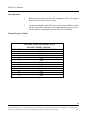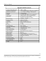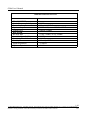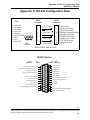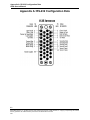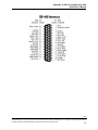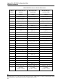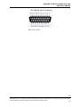
1
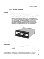
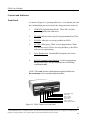
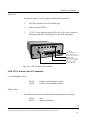
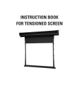
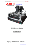
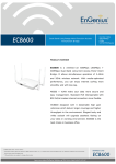
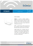
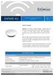
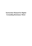
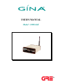
USER'S MANUAL Model : 2000-64K TM GINA User’s Manual GINA MODEL 2000-64K Overview GINA Model 2000-64K is a stand-alone, high frequency data transceiver using spread spectrum technology. GINA 2000-64K capabilities include synchronous data transmission at speeds to 64 Kbps at the data port with EIA 562/ RS-232, EIA530/RS-530, and V.11 (V.35) interfaces. GINA 2000-64K receives and transmits data in the frequency range of 2.404 - 2.478 Ghz at air speeds of up to 186 Kbps. Communicating at this speed allows GINA 2000-64K to be a full (TDD) duplex link. GINA can be configured to be used as a point-topoint communication device. GINA 2000-64K contains a packet controller module with a custom communication protocol that provides communications handshaking, cyclic redundancy checking (CRC), packet sequencing, and flow control. Figure 6-1. GINA 64K Transceiver Operation This section contain operating instructions for the GINA transceiver, including controls and indicators, DTE requirements, channel selection, and voice operation. 1-1 ©1999 GRE America, Inc. All rights reserved. This material is the property of GRE America, Inc. Copying or reproducing this material is strictly prohibited. All violators shall be prosecuted to the fullest extent of the law. 1/99 GINA User’s Manual Controls and Indicators Front Panel As shown in Figure 6-2, operating indicators, a voice handset jack, and the command data port are located on the front panel and consists of: 1. PWR LED (Light Emitting Diode). This LED is lit when power is applied to the transceiver. 2. TX LED. Indicates that a signal is being transmitted by GINA. 3. RX LED. Indicates a receiving condition on GINA. 4. ST LED. When green, GINA is receiving good data. When red, data has errors, GINA is receiving bad data, or the GINA units are not synchronizing. 5. Voice Handset Jack. Standard RJ22 telephone jack for the GINA handset. 6. RS-232 Command Control Data Port. Used for programming during GINA setup. This port communicates at 9600 kbps asynchronous only. NOTE: GINA only operates with the handset supplied with the unit. Do not attempt to use a standard telephone handset. Voice Handset Jack Status LED Receive LED Transmit LED Power LED GINA Setup Port Power ON/OFF Switch Figure 6-2. GINA Transceiver Front Panel 1-2 ©1999 GRE America, Inc. All rights reserved. This material is the property of GRE America, Inc. Copying or re-producing this material is strictly prohibited. All violators shall be prosecuted to the fullest extent of the law. 1/99 GINA User’s Manual Rear Panel As shown in Figure 6-3, the rear panel contains three connectors: 1. The GINA antenna jack (reverse SMA type). 2. Data Connector (DB-25). 3. 12 VDC. Power connector for the GINA AC to DC power converter. The center connector is 12 VDC positive; the outside is grounded. 12 - Volt DC Power Supply Jack Center Pole Positive Receiver Signal Strength Indicator Jacks DB25 RS-232, RS-530 or V.11/V.35 Connector Antenna Connector Reverse SMA Type Figure 6-3. GINA Transceiver Rear Panel GRE GINA Interface Board Commands Cyclic Redundancy Check CK=00 CK=01 Disable cyclic redundancy check. Enable cyclic redundancy check. Master / Slave One radio must always be in control of the transmit and receiver timing. MS=00 MS=01 Slave Master (control unit) 1-3 ©1999 GRE America, Inc. All rights reserved. This material is the property of GRE America, Inc. Copying or re-producing this material is strictly prohibited. All violators shall be prosecuted to the fullest extent of the law. 1/99 GINA User’s Manual Data Filter Selection FL=01 FL=02 FL=03 Factory Set to FL=02 FL=04 RF Channel Selection Channel selection should be the same on both slave and master. CH=01~12 Transmit Key ON TX=00 TX=01 This setting is for normal operation. 10 sec transmit - test purposes only Transmit Clock Selection CS=00 CS=01 CS=02 Internal transmit clock External transmit clock Loop back command (slave only). This means clock and data lines are looped back. txd=rxd, ctxc=rxc DR=01 DR=02 DR=03 DR=04 DR=05 9.6 19.2 38.4 56 64 Data Speed Selection Kbps Synchronous Kbps Synchronous Kbps Synchronous Kbps Synchronous Kbps Synchronous. This setting is also used to allow asynchronous data communication automatically at speeds of 1.2 to 19.2 Kbps. Revision of Software This is factory set but may be determined by checking the Display Status. The correct settings must be used. RV=15 1-4 ©1999 GRE America, Inc. All rights reserved. This material is the property of GRE America, Inc. Copying or re-producing this material is strictly prohibited. All violators shall be prosecuted to the fullest extent of the law. 1/99 GINA User’s Manual Display Status Follows any carriage return. Examples: GINA LOCAL STATUS = CD=00 CK=00 CH=01 CS=00 DR=05 ID=01 IN=01 MS=01 PO=01 FL=02 ELAPSED SECONDS = 000000060 ERRORED SECONDS = 000000000 DV=01 RV=15 HF=00 TX=00 GINA REMOTE STATUS: CD:00 CK:00 CH:01 CS:00 DR:05 DV:01 HF:00 ID:02 IN:01 MS:00 PO:01 FL=02 RV:15 TX:00 ELAPSED SECONDS = 000000120 ERRORED SECONDS = 000000001 Data or Voice DV=00 DV=01 Voice mode, data flow is de-activated. Voice is full-duplex through the handset. Data mode, voice operation is de-activated. Radio Transmit Hardware Flow HF=00 HF=01 Transmit and receiver are automatic. RTS high activates transmit and receive. Transmit Clock Interface IN=01 IN=02 RS-232 RS-449/V.11(.35) This must be set in programming to operate, but specified at time of order for hardware. Hardware is factory configured only. 1-5 ©1999 GRE America, Inc. All rights reserved. This material is the property of GRE America, Inc. Copying or re-producing this material is strictly prohibited. All violators shall be prosecuted to the fullest extent of the law. 1/99 GINA User’s Manual Carrier Detect CD=00 Carrier detector activates immediately every error occurrence. This setting causes the CD line to drop immediately if there is a dropout in the GINA to GINA link up. CD=01 Carrier detector holds 2 seconds every error occurrence. This allows the CD link not to drop unless the GINA link fade persists longer than 2 seconds. RE=01 TWICE TYPE Resets unit to factory default settings. This command must be entered twice. The re-set must then be followed by configuring the channel using the CH command. RE Reset Command After reset: RC=03 For 2.4 Ghz GINA Transmitter Power Code The Transmitter Power Code command is operational and is slated for future product development. It should be se to 01. 01 = Full Power 02 = 3db down 03 = 6db down 04 = 20db down Remote Status Allows over the air configuration of the remote’s status. Type the command to change and use a colon (:) instead of an equal sign (=). For example: To change the Carrier Detect Code, type: CD:01 Identification Code The ID command is non-operational and is slated for future product development. It should be set to 01. 1-6 ©1999 GRE America, Inc. All rights reserved. This material is the property of GRE America, Inc. Copying or re-producing this material is strictly prohibited. All violators shall be prosecuted to the fullest extent of the law. 1/99 GINA User’s Manual Frame Errors Per Second Counter Indicates path and data integrity of the link. ZC=00 ZC=01 ZC=02 To hide To display To clear and reset Operations 1. User must confirm all commands as shown above by using a computer connected to the command control data port at 9600 Kbps with a terminal emulation program. 2. To change a parameter, type the command letters, an “=” symbol, and then both digits of the desired numerical value. Example: to change the Master/Slave configuration to Slave, type MS=00 then click on return. 3. You must set up your terminal emulation program so that it does not automatically add a line feed (LF) after every carriage return (CR). The only command format that works is CMD CR not CMD CRLF. 4. Command MS has to be determined for slave or master. 5. Select RF Channel - Between 01~12 on the 2000-64K 6. The RF Channel must be the same between master and slave. 7. Select transmit clock internal or external depending on your application. 8. When the power is turned on, the master transmits. The slave follows the master. When you have a green LED on the ST, you have a good quality data link between the GINA units. When both GINA’s link, the transmit and receiver LED’s flash continuously at approximately 10 flashes per second. 1-7 ©1999 GRE America, Inc. All rights reserved. This material is the property of GRE America, Inc. Copying or re-producing this material is strictly prohibited. All violators shall be prosecuted to the fullest extent of the law. 1/99 GINA User’s Manual Voice Operation 1. Both master and slave must have DV command to 00 for voice option. Data is not active when voice is in use. 2. Connect the handsets to the RJ22 Jack (on the front of GINA) to both the slave and master. When the voice command mode is set, you can use the handsets to talk duplex over the link (325 to 4000Hz). Channel Frequency Tables CHANNEL 1 2 3 4 5 6 7 8 9 10 11 12 CHANNEL CODE SWITCH SETTINGS FOR GINA MODEL 2000-64K FREQUENCY (GHz) 2410 2415 2420 2425 2430 2435 2440 2445 2450 2455 2460 2465 1-8 ©1999 GRE America, Inc. All rights reserved. This material is the property of GRE America, Inc. Copying or re-producing this material is strictly prohibited. All violators shall be prosecuted to the fullest extent of the law. 1/99 GINA Users Manual 2000-64K SPECIFICATIONS Adjacent Channel Rejection Baud Rate Asynchronous Baud Rate Synchronous Channels Control Data Format Dimensions Dynamic Range Frequency Range Indicators Modulation PN PN Rate Operating Mode Operating Temperature Data Filter Power Consumption Power Requirements Radio Technique Range Nominal Range Indoor Range Outdoor Relative Humidity Systems Gain Transmission Delay Voice Option Interface Turn around Time -40dB = 10MHz 1.2 to 19.2 Kbps Duplex TDD -RS-232 (DB25F) 9.6 to 64 Kbps, Full Duplex TDD (DB25F) 12 Programmable CTS, RTS, DTR, DSR, TC, RC, external TC 8 bits, no parity, 1 stop, for command port (1.52H) x (4.17W) x (5.0D) (38.6mm) x (105.9mm) x (127mm) -100 dBm ~ -30 dBm 2.404 to 2.478 Ghz PWR, TxD, RxD, DQ Bi-Phase Shift Keying (BPSK) 11 Chip 5. 5 MHz Point -to-Point -20 to +60 Degrees C 4 selectable FL=01 ~ FL=04 10 Watt Maximum 8 to 13.8 VDC Spread Spectrum Direct Sequence 800+feet 500 to 1500+feet 18+ Miles - Direct Line-of-Sight FCC Compliant 0-90% Non-Condensing 119 dB 5mSec. RJ22 80mSec. Weight 16 oz. 1-9 © 2000 GRE America, Inc. All rights reserved. This material is the property of GRE America, Inc. Copying or re-producing this material is strictly prohibited. All violators shall be prosecuted to the fullest extent of the law. 1/2000 GINA User’s Manual 2000-64K SPECIFICATIONS TRANSMITTER Carrier Frequency Stability Power Consumption Spurious Output Output Power RECEIVER Bit Error Rate Local Oscillator Stability Sensitivity Threshold Stand-by Power Signal Acquisition Spurious Rejection 25 KHz 800mA @ 12VDC FCC Part 15, meets 15.245 & 15.247 800mW (29dBm) 10-8@ -93dBm, 10-6@ -96dBm 25 KHz -100 dBm 300mA@ 12VDC <0.2mSec. -50 dB 1-10 ©1999 GRE America, Inc. All rights reserved. This material is the property of GRE America, Inc. Copying or re-producting this material is strictly prohibited. All violators shall be prosecuted to the fullest extent of the law. 1/99 Appendix A: RS-232 Configuration Data GINA User’s Manual Appendix A: RS-232 Configuration Data DB-9 Connector PIN 1 - Not Used 2 - RX Data 3 - TX Data 4 - Not Used 5 - Ground 5 4 3 2 1 6 -12V DC PWR 7 - RTS 8 - CTS 9 8 7 6 9 - Not Used DB-9 Connector 1 2 3 4 5 6 7 8 9 DB-25 Connector —Not Used— —Not Used— —Not Used— —Not Used— 8 3 2 20 7 6 4 5 22 DCD (Carrier) RTX (Receive Data) TXD (Transmit Data) DTR (Data Terminal Ready) GND (Signal Ground) DSR (Data Set Ready) RTS (Request to Send) CTS (Clear to Send) RI (Ring Indicator) DB-9 to DB-25 SERIAL PORT RS-232 Interface SIGNAL DESIGNATION PIN NUMBER PIN NUMBER SIGNAL DESIGNATION 1 Protective Ground Secondary Transmitted Data 14 DCE Transmitter Signal Element Timing 15 Secondary Received Data 16 Receiver Signal Element Timing 17 18 Secondary Request to Send 19 Data Terminal Ready 20 Signal Quality Detector 21 Ring Indicator 22 Data Signal Rate Selector 23 DTE Transmitter Signal Element Timing 24 25 2 Transmitted Data 3 Received Data 4 Request to Send 5 Clear to Send 6 Data Set Ready 7 Signal Ground/Common Return 8 Received Line Signal Detector 9 + Voltage 10 – Voltage 11 12 Secondary Received Line Signal Indicator 13 Secondary Clear to Send A-1 ©1999 GRE America, Inc. All rights reserved. This material is the property of GRE America, Inc. Copying or reproducing this material is strictly prohibited. All violators shall be prosecuted to the fullest extent of the law. 1/99 Appendix A: RS-232 Configuration Data GINA User’s Manual Appendix A: RS-232 Configuration Data A-2 ©1999 GRE America, Inc. All rights reserved. This material is the property of GRE America, Inc. Copying or reproducing this material is strictly prohibited. All violators shall be prosecuted to the fullest extent of the law. 1/99 Appendix A: RS-232 Configuration Data GINA User’s Manual A-3 ©1999 GRE America, Inc. All rights reserved. This material is the property of GRE America, Inc. Copying or reproducing this material is strictly prohibited. All violators shall be prosecuted to the fullest extent of the law. 1/99 Appendix A: RS-232 Configuration Data GINA User’s Manual GINA DB-25F Connector Pin-Out Information DB-25 PIN # DB-25 PIN-OUT for RS-232 DB-25 PIN-OUT for RS-449 DB-25 PIN-OUT for V.11 (V.35) 1 Shield Shield Shield 2 Transmitted Data Transmitted Data (A) Transmitted Data (A) 3 Received Data Received Data (A) Received Data (A) 4 Request to Send Request to Send (A) Request to Send 5 Clear to Send Clear to Send (A) Clear to Send 6 DSR DSR (A) DSR 7 Signal Ground Signal Ground Signal Ground 8 DCD DCD (A) DCD 9 RXC (B) RXC (B) 10 DCD (B) 11 TX EXT CLK (B) TX EXT CLK (B) 12 TX CLK (B) TX CLK (B) 13 Clear to Send (B) 14 TXD (B) TXD (B) TXC (A) TXC (A) RXD (B) RXD (B) RXC (A) RXC (A) 15 TX CLK 16 17 RX CLK 18 19 20 RTS (B) DTR DTR (A) DTR 21 22 DSR (B) 23 DTR (B) 24 EXT TX CLK TX EXT CLK (A) TX EXT CLK (A) 25 Call Pulse (5V DC<=10mA) Call Pulse (5V DC<=10mA) Call Pulse (5V DC<=10mA) A-4 ©1999 GRE America, Inc. All rights reserved. This material is the property of GRE America, Inc. Copying or reproducing this material is strictly prohibited. All violators shall be prosecuted to the fullest extent of the law. 1/99 Appendix A: RS-232 Configuration Data GINA User’s Manual GINA DB-25F Pin-Out Numbering Note: GINA is DCE. A-5 ©1999 GRE America, Inc. All rights reserved. This material is the property of GRE America, Inc. Copying or reproducing this material is strictly prohibited. All violators shall be prosecuted to the fullest extent of the law. 1/99 Troubleshooting GINA User’s Manual Warranty Introduction This section contains user information about GRE’s limited warranty. Limited Warranty General GRE America, Inc. warrants all parts of each new product to be of sound design, good material and workmanship, and will repair or exchange any parts proven to be defective under normal use at no charge for a period of 12 months from the date of sale to the end user. Defects will be corrected by GRE America. There will be no charge for labor for a period of 12 months from the date of original sale, except as provided below. Overtime premiums and/or expedited handling and shipping costs must be paid by the owner. Warranty Limitations This warranty does not apply to equipment or parts that have been subject to accident, abuse, incorrect service, alterations, service by non-authorized service personnel, misuse, or on units upon which the warranty seal has been removed, altered, or mutilated. A copy of the warranty certificate or purchase receipt must be supplied to GRE America when requesting service. Equipment must be sent to GRE America at the owner’s expense and will be returned via surface carrier at no cost to the owner. This warranty is strictly limited to the terms indicated herein, and no other warranties or remedies thereunder, express or implied, shall be binding on GRE America. A-6 ©1999 GRE America, Inc. All rights reserved. This material is the property of GRE America, Inc. Copying or reproducing this material is strictly prohibited. All violators shall be prosecuted to the fullest extent of the law. 1/99