1
TE800 Series
TE820B/TE820
User Manual
601-00019
Rev. A1
Digium, Inc.
445 Jan Davis Drive NW
Huntsville, AL 35806
United States
Main Number: 1.256.428.6000
Tech Support: 1.256.428.6161
U.S. Toll Free: 1.877.344.4861
Sales: 1.256.428.6262
www.digium.com
www.asterisk.org
www.asterisknow.org
© Digium, Inc. 2011
All rights reserved.
No part of this publication may be copied, distributed, transmitted, transcribed, stored in a
retrieval system, or translated into any human or computer language without the prior written
permission of Digium, Inc.
Digium, Inc. has made every effort to ensure that the instructions contained in this document
are adequate and error free. The manufacturer will, if necessary, explain issues which may
not be covered by this documentation. The manufacturer’s liability for any errors in the
documents is limited to the correction of errors and the aforementioned advisory services.
This document has been prepared for use by professional and properly trained personnel,
and the customer assumes full responsibility when using it.
Adobe and Acrobat are registered trademarks, and Acrobat Reader is a trademark of Adobe
Systems Incorporated.
Asterisk, Digium, Switchvox, and AsteriskNOW are registered trademarks and Asterisk
Business Edition, AsteriskGUI, and Asterisk Appliance are trademarks of Digium, Inc.
Any other trademarks mentioned in the document are the property of their respective owners.
Digium, Inc.
Page 2
Safety Certification and Agency Approvals
Safety:
UL/CSA 60950-1 2nd Ed.
IEC 60950-1:2005 (2nd Ed.) +A1:2009
EN 60950-1:2006 (2nd Ed.) +A11:2009 +A1:2010
AS/NZS 60950-1 1st Ed.
Note: Finland, Norway and Sweden require that equipment using this
product must be located in a Restricted Access Location (RAL).
Other:
CE Mark (European Union)
2002/95/EC Restrictions on Hazardous Substances (RoHS), 2005/747/EC
lead free exemption (Annex C)
Telecom:
FCC Part 68, TIA-968-B
Industry Canada CS-03, Issue 9, Part II
AS/ACIF S016: 2001
AS/ACIF S038: 2001
ICASA (TE405P/TE407P/TE410P/TE412P)
ETSI TBR4 November 1995 as amended by TBR4/A1 December 1997
ETSI TBR12, TBR12/A1 December 1993
ETSI TBR13 January 1996
Digium, Inc.
Page 3
EMC:
47 CFR Part 15, Subpart B / 47 CFR Part 15, Subpart B, Class A
EN55022:2010 IEC CISPR22:2009 Class A
IEC 61000
EN 61000-3-2:2006 +A1 & A2
EN 61000-3-3:2008
EN 55024:2010
CNS13438:2006
VCCI V-3 2010.04
Digium, Inc.
Page 4
Federal Communications Commission Part 68
This equipment complies with Part 68 of the FCC rules and the
requirements adopted by the ACTA. On the back of the TE800 Series
printed circuit board is a label that contains, among other information, a
product identifier in the format US:AAAEQ##TXXXX. If requested, this
number must be provided to the telephone company. A plug and jack used
to connect this equipment to the premises wiring and telephone network
must comply with the applicable FCC Part 68 rules and requirements
adopted by the ACTA.
If the TE800 Series causes harm to the telephone network, the telephone
company may notify you in advance that temporary discontinuance of
service may be required. But if advance notice is not practical, the
telephone company will notify you as soon as possible. Also, you will be
advised of your right to file a complaint with the FCC if you believe it is
necessary.
The telephone company may make changes in its facilities, equipment,
operations or procedures that could affect the operation of the equipment.
If this happens, the telephone company will provide advance notice in
order for you to make necessary modifications to maintain uninterrupted
service.
If you experience problems with the TE800 Series, contact Digium, Inc.
(+1.256.428.6161) for repair and/or warranty information. If the
equipment is causing harm to the telephone network, the telephone
company may request that you disconnect the equipment until the
problem is resolved.
Digium, Inc.
Page 5
FCC Part 15
This device complies with part 15 of FCC rules. Operation is subject to
the following two conditions: (1) This device may not cause harmful
interference, and (2) This device must accept any interference received,
including interference that may cause undesired operation.
Industry Canada Compliance Information
Notice: The Industry Canada label applied to the product (identified by
the Industry Canada logo or the "IC:" in front of the certification/
registration number) indicates that the Industry Canada technical
specifications were met.
Digium, Inc.
Page 6
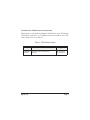
Introduction to TE800 Series Documentation
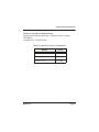
This manual is a user guide for Digium’s TE800 Series cards. The Digium
TE800 Series cards are a T1/E1 capable card series created for voice. The
cards in this series are as follows:
Table 1: TE800 Series Cards
Model
TE820B
TE820
Digium, Inc.
Features
8 Ports, Echo Cancellation
8 Ports
Type
PCI Express
PCI Express
Page 7
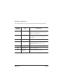
Document Organization
The TE800 Series user’s guide is organized in the following manner:
Chapter/
Appendix
Title
Description
1
Overview
Identifies the features of the card you received. This
chapter covers applications and uses of the TE800
Series cards in the real world.
2
Card Installation
Provides instructions for installing the card in your
PC, acquiring correct drivers, and checking device
compatibility.
3
Configuration
Provides examples for configuring dial plan options.
4
Troubleshooting
Explains resolutions to common problems and
frequently asked questions pertaining to card
installation and usage.
A
Pin Assignments
Lists the connectors and pin assignments.
B
Specifications
Details card specifications.
C
Glossary and
Acronyms
Defines terms related to this product.
Digium, Inc.
Page 8
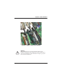
Symbol Definitions
Caution statements indicate a condition where damage to the unit or
its configuration could occur if operational procedures are not
followed. To reduce the risk of damage or injury, follow all steps or
procedures as instructed.
The ESD symbol indicates electrostatic sensitive devices. Observe
precautions for handling devices. Wear a properly grounded
electrostatic discharge (ESD) wrist strap while handling the device.
The Electrical Hazard Symbol indicates a possibility of electrical
shock when operating this unit in certain situations. To reduce the
risk of damage or injury, follow all steps or procedures as
instructed.
Digium, Inc.
Page 9
Important Safety Instructions
User Cautions
Servicing.
Do not attempt to service this card unless specifically instructed to do
so. Do not attempt to remove the card from your equipment while
power is present. Refer servicing to qualified service personnel.
Water and Moisture.
Do not spill liquids on this unit. Do not operate this equipment in a
wet environment.
Heat.
Do not operate or store this product near heat sources such as
radiators, air ducts, areas subject to direct, intense sunlight, or other
products that produce heat.
Static Electricity.
To reduce the risk of damaging the unit or your equipment, do not
attempt to open the enclosure or gain access to areas where you are
not instructed to do so. Refer servicing to qualified service personnel.
Save these instructions for future reference.
Digium, Inc.
Page 10
TABLE OF CONTENTS
Chapter 1
Overview . . . . . . . . . . . . . . . . . . . . . . . . . . . . . . . . . . . . . . . . . . . . . . . 15
Echo-Cancellation . . . . . . . . . . . . . . . . . . . . . . . . . . . . . . . . . . . . . . 20
What is Asterisk®? . . . . . . . . . . . . . . . . . . . . . . . . . . . . . . . . . . . . . 21
Asterisk as a Phone Switch (PBX) . . . . . . . . . . . . . . . . . . . . . . . . . 21
Asterisk as a Gateway . . . . . . . . . . . . . . . . . . . . . . . . . . . . . . . . . . 21
Asterisk in the Call Center . . . . . . . . . . . . . . . . . . . . . . . . . . . . . . . 22
Asterisk in the Network . . . . . . . . . . . . . . . . . . . . . . . . . . . . . . . . . . 22
Asterisk Everywhere . . . . . . . . . . . . . . . . . . . . . . . . . . . . . . . . . . . . 23
Chapter 2
Card Installation . . . . . . . . . . . . . . . . . . . . . . . . . . . . . . . . . . . . . . . . . 24
Unpacking the Card . . . . . . . . . . . . . . . . . . . . . . . . . . . . . . . . . . . .25
Shipment Inspection . . . . . . . . . . . . . . . . . . . . . . . . . . . . . . . . . . . . 25
Identifying Ports . . . . . . . . . . . . . . . . . . . . . . . . . . . . . . . . . . . . . . . 26
T1/E1 Selection . . . . . . . . . . . . . . . . . . . . . . . . . . . . . . . . . . . . . . . 29
Connecting Timing Cables . . . . . . . . . . . . . . . . . . . . . . . . . . . . . . . 30
Slot Compatibility . . . . . . . . . . . . . . . . . . . . . . . . . . . . . . . . . . . . . . 33
Hardware Installation . . . . . . . . . . . . . . . . . . . . . . . . . . . . . . . . . . . 35
Software Installation . . . . . . . . . . . . . . . . . . . . . . . . . . . . . . . . . . . . 37
Installing Asterisk . . . . . . . . . . . . . . . . . . . . . . . . . . . . . . . . . . . . . . 42
Chapter 3
Configuration . . . . . . . . . . . . . . . . . . . . . . . . . . . . . . . . . . . . . . . . . . . . 44
Digium, Inc.
Page 11
Table Of Contents
Configuring Card Features . . . . . . . . . . . . . . . . . . . . . . . . . . . . . . . 45
Configuring T1/E1 Lines . . . . . . . . . . . . . . . . . . . . . . . . . . . . . . . . .48
Testing Your Configuration . . . . . . . . . . . . . . . . . . . . . . . . . . . . . . . 56
Chapter 4
Troubleshooting . . . . . . . . . . . . . . . . . . . . . . . . . . . . . . . . . . . . . . . . . 57
Appendix A
Pin Assignments . . . . . . . . . . . . . . . . . . . . . . . . . . . . . . . . . . . . . . . . . 63
Appendix B
Specifications . . . . . . . . . . . . . . . . . . . . . . . . . . . . . . . . . . . . . . . . . . . 66
Appendix C
Glossary and Acronyms . . . . . . . . . . . . . . . . . . . . . . . . . . . . . . . . . . . 68
Digium, Inc.
Page 12
List of Figures
Figure 1:
Figure 2:
Figure 3:
Figure 4:
Figure 5:
Figure 6:
Figure 7:
Figure 8:
Figure 9:
Figure 10:
Figure 11:
Digium, Inc.
Sample Legacy Phone Application . . . . . . . . . . . . . .17
Sample Channel Bank Application . . . . . . . . . . . . . .18
Sample IP Phone Application . . . . . . . . . . . . . . . . . . 19
TE820B . . . . . . . . . . . . . . . . . . . . . . . . . . . . . . . . . . . 26
TE820 . . . . . . . . . . . . . . . . . . . . . . . . . . . . . . . . . . . . 27
Y-adapter Dongle . . . . . . . . . . . . . . . . . . . . . . . . . . . 28
Dongle Split End . . . . . . . . . . . . . . . . . . . . . . . . . . . . 28
Differential Timing Port Example . . . . . . . . . . . . . . . 31
Legacy Timing Port Example . . . . . . . . . . . . . . . . . . 32
Motherboard Slots . . . . . . . . . . . . . . . . . . . . . . . . . . 33
Insert the Card . . . . . . . . . . . . . . . . . . . . . . . . . . . . .35
Page 13
List of Tables
Table 1:
Table 1:
Table A-1:
Table A-2:
Table A-3:
Table B-4:
Digium, Inc.
TE800 Series Cards . . . . . . . . . . . . . . . . . . . . . . . 7
Card Identifiers . . . . . . . . . . . . . . . . . . . . . . . . . . . 40
TE800 Series RJ45 Telco Port Connector. . . . . . . . . 63
Dongle Split A RJ45 Telco Port Connector . . . . . . . . 64
Dongle Split B RJ45 Telco Port Connector . . . . . . . . 65
Maximum Power Consumption . . . . . . . . . . . . . . . . .67
Page 14
Chapter 1
Overview
The Digium TE800 Series is a T1/E1/J1 capable card series created for
voice. They support industry standard protocols, including Robbed Bit
Signaling (also known as CAS or Channel Associated Signaling), CCS
(Common Channel Signaling), E&M, and Primary Rate ISDN (PRI).
They are also capable of DACSing channels from one span to another.
The TE800 Series cards are ideal for connecting phones to a channel
bank, connecting to T1/E1 switches, or connecting to a legacy PBX. The
Y-adapter dongle that Digium engineered for use with the Digium TE800
Series allows twice the amount of spans to fit in a single PC slot, taking
up less space to allow for more peripherals. Designed to be fully
compatible with existing software applications and integrate fully with
the Asterisk platform, the TE800 Series cards allow many advanced call
features.
This manual is for use with the TE820/TE820B PCI Express card. These
are identified collectively as the TE800 Series cards throughout this
manual.
Digium, Inc.
Page 15
Chapter 1: Overview
Voice Modes:
PRI CPE and PRI NET
– NI1
– NI2
– EuroISDN
– 4ESS (AT&T)
– 5ESS (Lucent)
– DMS100
– Q.SIG
E&M
– Wink
– Feature Group B
– Feature Group D
FXO and FXS
– Ground Start
– Loop Start
– Loop Start with Disconnect Detect
The TE800 Series cards can be used to connect your Asterisk machine to
the PSTN world, your channel bank, or even another PBX. This is
accomplished via a T1/E1 interface. The cards allow Asterisk software to
Digium, Inc.
Page 16
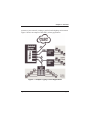
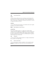
Chapter 1: Overview
connect to your network, creating a professional telephony environment.
Figure 2 shows an example of the card’s primary application.
Figure 1: Sample Legacy Phone Application
Digium, Inc.
Page 17
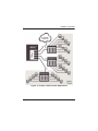
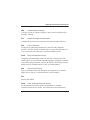
Chapter 1: Overview
Figure 2: Sample Channel Bank Application
Digium, Inc.
Page 18
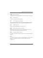
Chapter 1: Overview
Figure 3: Sample IP Phone Application
Digium, Inc.
Page 19
Chapter 1: Overview
Echo-Cancellation
Users connecting their TE800 Series cards to the PSTN or other devices
are likely to be placing calls that will result, at some point, in an
unbalanced 4-wire/2-wire hybrid. The result of this hybrid is the
reflection of a near-end echo to the calling party. Elimination of this echo
is the responsibility of echo cancellation.
The TE800 Series cards, unless otherwise equipped, utilize Asterisk to
perform software-based echo cancellation. Asterisk maintains a number
of open source echo cancelers. These open source echo cancelers provide
a moderate level of echo cancellation, but are not capable of dealing with
higher levels of, or more advanced, echoes.
Digium recommends that those users concerned about echo cancellation
purchase the VPMOCT256 hardware echo cancellation module. The
VPMOCT256 may be combined with any of the TE800 Series cards.
The VPMOCT256 is designed to handle up to 128ms of echo cancellation
across all channels and provides a G.168 compliant echo cancellation
solution.
If equipped and not explicitly disabled in chan_dahdi.conf, the
VPMOCT256 will automatically operate and cancel all network echo
within its tail range (1024 taps).
Digium, Inc.
Page 20
Chapter 1: Overview
What is Asterisk®?
Asterisk is the world’s leading open source telephony engine and tool kit.
Offering flexibility unheard of in the world of proprietary
communications, Asterisk empowers developers and integrators to create
advanced communication solutions...for free. Asterisk is released as open
source under the GNU General Public License (GPL), and it is available
for download free of charge. Asterisk is the most popular open source
telephony software available, with the Asterisk Community being the top
influencer in VoIP.
Asterisk as a Phone Switch (PBX)
Asterisk can be configured as the core of an IP or hybrid PBX, switching
calls, managing routes, enabling features, and connecting callers with the
outside world over IP, analog (POTS), and digital (T1/E1/J1/BRI)
connections.
Asterisk runs on a wide variety of operating systems including Linux,
Mac OS X, OpenBSD, FreeBSD, and Sun Solaris. It provides all of the
features you would expect from a PBX including many advanced features
that are often associated with high end (and high cost) proprietary PBXs.
Asterisk's architecture is designed for maximum flexibility and supports
Voice over IP in many protocols, and can interoperate with almost all
standards-based telephony equipment using relatively inexpensive
hardware.
Asterisk as a Gateway
It can also be built out as the heart of a media gateway, bridging the
legacy PSTN to the expanding world of IP telephony. Asterisk’s modular
Digium, Inc.
Page 21
Chapter 1: Overview
architecture allows it to convert between a wide range of communications
protocols and media codecs.
Asterisk as a Feature/Media Server
Need an IVR? Asterisk’s got you covered. How about a conference
bridge? Yep. It’s in there. What about an automated attendant? Asterisk
does that too. How about a replacement for your aging legacy voicemail
system? Can do. Unified messaging? No problem. Need a telephony
interface for your web site? Okay.
Asterisk in the Call Center
Asterisk has been adopted by call centers around the world based on its
flexibility. Call center and contact center developers have built complete
ACD systems based on Asterisk. Asterisk has also added new life to
existing call center solutions by adding remote IP agent capabilities,
advanced skills-based routing, predictive and bulk dialing, and more.
Asterisk in the Network
Internet Telephony Service Providers (ITSPs), Competitive Local
Exchange Carriers (CLECs) and even first-tier incumbents have
discovered the power of open source communications with Asterisk.
Feature servers, hosted services clusters, voicemail systems, and pre-paid
calling solutions, all based on Asterisk have helped reduce costs and
enabled flexibility.
Digium, Inc.
Page 22
Chapter 1: Overview
Asterisk Everywhere
Asterisk has become the basis for thousands of communications
solutions. If you need to communicate, Asterisk is your answer. For more
information on Asterisk, visit http://www.asterisk.org or http://
www.digium.com.
Digium, Inc.
Page 23
Chapter 2
Card Installation
This chapter provides the following information:
Unpacking the Card on page 25
Shipment Inspection on page 25
Identifying Ports on page 26
T1/E1 Selection on page 29
Connecting Timing Cables on page 30
Slot Compatibility on page 33
Hardware Installation on page 35
Software Installation on page 37
Note: The TE800 Series card installation instructions are written so
that they will apply to any card in the series. Examples and card
specific information are included as needed.
Digium, Inc.
Page 24
Chapter 2: Card Installation
Unpacking the Card
When you unpack your card, carefully inspect it for any damage that may
have occurred in shipment. If damage is suspected, file a claim with the
carrier and contact your reseller from which the card was purchased, or
contact Digium Technical Support (+1.256.428.6161). Keep the original
shipping container to use for future shipment or proof of damage during
shipment.
Note: Only qualified service personnel should install the card. Users
should not attempt to perform this function themselves. The installer
must ensure that the equipment is permanently connected equipment,
pluggable type B or connected to a socket-outlet that has been checked
to ensure that it is reliably earthed in accordance with the National
Electrical Code.
Shipment Inspection
The following items are included in shipment of the TE800 Series:
TE800 Series card (TE820/820B)
Four Y-adapter dongles
Digium, Inc.
Page 25
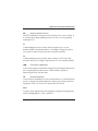
Chapter 2: Card Installation
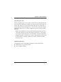
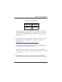
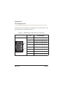
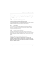
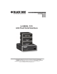
Identifying Ports
The TE800 Series cards consists of 4 RJ45 ports and eight status LEDs.
The ports are used for connecting T1, E1, or J1 cables via Y-adapter
dongles. Refer to Figure 4 on page 26 and Figure 5 on page 27 to locate
the ports and status LEDs.
Note: The TE800 Series cards can be used without Y-adapter dongles,
but only spans 1 through 4 will be accessible.
Legacy
Timing
Port
Differential
Timing
Port
Port
1
2
3
4
PCI Express
Connector
Voice
Processing
Module
Figure 4: TE820B
Digium, Inc.
Page 26
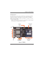
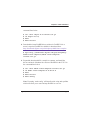
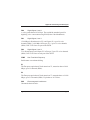
Chapter 2: Card Installation
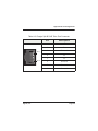
Span
Status
LEDs
Figure 5: TE820
Digium, Inc.
Page 27
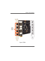
Chapter 2: Card Installation
The Y-adapter dongles are provided for accessing all 8 spans on
the TE800 Series cards. Refer to Figure 6 and Figure 7 to identify a
dongle and its split end ports. Pin assignments are available starting on
page 63.
Figure 6: Y-adapter Dongle
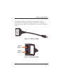
Split A
Spans 1-4
Split B
Spans 5-8
Figure 7: Dongle Split End
Digium, Inc.
Page 28
Chapter 2: Card Installation
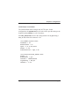
T1/E1 Selection
The TE800 Series cards can be configured for either T1 or E1 mode. The
T1/E1 mode may be specified in the drivers using either the
default_linemode=t1 or default_linemode=e1 module parameter when
the drivers are loaded. This will set the mode for all spans on the card.
T1 Mode (Recommended Method) - Include the following in
/etc/modprobe.d/dahdi.conf:
options wct4xxp default_linemode=t1
T1 Mode (Alternate Method):
# modprobe wct4xxp default_linemode=t1
E1 Mode (Recommended Method) - Include the following in
/etc/modprobe.d/dahdi.conf:
options wct4xxp default_linemode=e1
E1 Mode (Alternate Method):
# modprobe wct4xpp default_linemode=e1
Digium, Inc.
Page 29
Chapter 2: Card Installation
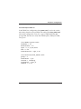
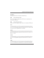
Connecting Timing Cables
The timing port allows up to three TE800 Series cards to share the same
sync (timing) source from the T1 line provider, or provide a consistent
sync source across multiple cards. This is a useful feature for fax modes
and some voice applications to prevent corruption due to timing slips on
the second, or third cards.
To utilize this feature, daisy-chain the P3 connector between each card
using the Digium 3-position, 10-pin timing cable. See Figure 8 on page 31
for an example.
Note: Certain previous model Digium products use a Legacy Timing
Port instead of the Differential Timing Port (P3 connector). If a card is
installed that has only a Legacy Timing Port, daisy-chain the P4
connector between each card using the Digium 4-position timing
cable. See Figure 9 on page 32 for an example.
Enable this feature in the drivers using the timingcable=1 switch when
the drivers are loaded:
# modprobe wct4xxp timingcable=1
Note: Do not hook up the Differential Timing Port and Legacy Timing
Port at the same time. Only one can be used at a time.
Digium, Inc.
Page 30
Chapter 2: Card Installation
Figure 8: Differential Timing Port Example
Digium, Inc.
Page 31
Chapter 2: Card Installation
Figure 9: Legacy Timing Port Example
Caution.
Only qualified service personnel should continue with
hardware installation and configuration of the TE800 Series
card. Non-qualified personnel should not attempt to perform
these functions themselves.
Digium, Inc.
Page 32
Chapter 2: Card Installation
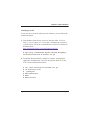
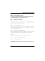
Slot Compatibility
Check your motherboard to verify that a compatible slot is available for a
TE800 Series card. To determine which slots you have on your
motherboard, identify them by comparing them to those shown in
Figure 10.
Slot Number:
0: AGP Pro Slot
1: 64-bit 5.0 volt PCI Slot
2: 64-bit 3.3 volt PCI Slot
3: 32-bit 5.0 volt PCI Slot
4: PCI Express 1-lane (x1) Slot
5: PCI Express 4-lane (x4) Slot
6: PCI Express 8-lane (x8) Slot
7: PCI Express 16-lane (x16) Slot
Figure 10: Motherboard Slots
Digium, Inc.
Page 33
Chapter 2: Card Installation
The TE820/TE820B card is keyed for a PCI Express 1-lane (x1) slot and
will work in any PCIe revision 1.0 compliant slot, including lane lengths
x4, x8, and x16. This means that in the motherboard shown in Figure 10,
the TE820/TE820B card will fit into Slots 4, 5, 6, or 7 (PCI Express), but
cannot fit into any of the other slots.
Digium, Inc.
Page 34
Chapter 2: Card Installation
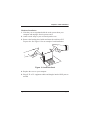
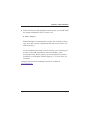
Hardware Installation
1. Now that you are acquainted with the cards, power down your
computer and unplug it from its power source.
2. Attach a static strap to your wrist and open the case.
3. Remove the bracket place holder and insert the card into a PCI
Express slot. See Figure 11 for an example of card installation.
Figure 11: Insert the Card
4. Replace the cover to your computer.
5. Plug all T1 or E1 equipment cables and dongles into the RJ45 ports as
needed.
Digium, Inc.
Page 35
Chapter 2: Card Installation
Caution.
This unit must be connected to the Telecommunications
Network in your country using an approved line cord (e.g. for
Australia use only line cords complying with ACA Technical
Standard TS008).
Caution.
This unit must be connected only to the appropriate
Telecommunications Network port (as approved for use in your
specific country).
Digium, Inc.
Page 36
Chapter 2: Card Installation
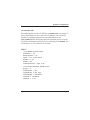
Software Installation
Digium hardware requires drivers and libraries that are not integrated
with the Linux kernel. Digium hardware is supported only under Linux.
Digium recommends CentOS, Debian, Red Hat, and Ubuntu distributions
of Linux. However, many other distributions are supported by Digium
Technical Support.
Digium’s software, including drivers and application software, may be
obtained from Digium’s download server at:
http://downloads.digium.com
For an introduction to Asterisk, Digium’s telephony software, including
additional information on its configuration, setup, and features, please
refer to:
http://www.asterisk.org
For the latest information on setting up and configuring DAHDI drivers
for your Digium hardware product, please refer to the latest release of this
manual which is available from the product-specific documentation
section at:
http://www.digium.com
To install your TE800 Series card, you will need:
Linux 2.6 kernel headers
Development libraries and headers for ncurses
Development libraries and headers for zlib and openssl
Development libraries and headers for newt
GCC and standard software build tools
It is recommended that you use the most recent version of the Asterisk,
DAHDI, and libpri software for the best results. If you have previously
Digium, Inc.
Page 37
Chapter 2: Card Installation
installed any of these, Digium recommends that you upgrade to the latest
“-current” version of each.
Note: DAHDI 2.6.0 or newer is required. If you are using the 1.4.x
series of Asterisk, you will need Asterisk 1.4.22 or newer.
Digium, Inc.
Page 38
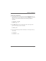
Chapter 2: Card Installation
1. After the machine has booted to Linux, log in and execute the
following command to list the devices detected by the PCI bus:
# lspci -nn | grep d161
Confirm that the output from lspci lists a device with Digium’s PCI
vendor ID which is “d161”. The screen output should be similar to the
following:
04:08.0 Communication controller [0780]: Digium,
Inc. Device [d161:<card identifier>] (rev 02)
Note: The output from lspci may or may not state “Unknown
device”. If it does, this does not indicate a problem.
In the PCI device listing shown above, <card identifier> will be
populated with one of the identifiers listed in the table below.
Digium, Inc.
Page 39
Chapter 2: Card Installation
Table 1: Card Identifiers
Model
TE820B
TE820
Identifier
800B
800B
A Digium TE800 Series (TE820B/TE820) card identifier should be
listed. If a matching card identifier is not listed, then your machine is
not PCI Express compatible, and the card will not work with your
motherboard.
2. Download the latest version of libpri. Substitute the version of libpri
for the X.X in the command line below. libpri is available for
download from:
http://downloads.digium.com/pub/telephony/libpri
# wget http://downloads.digium.com/pub/telephony/
libpri/libpri-X.X.current.tar.gz
Note: There is no coorelation between the versioning of libpri and
Asterisk. The libpri 1.4 branch will function with the Asterisk 1.6 and
1.8 branches.
3. Expand the downloaded file, compile its contents, and install the
libraries. Substitute the version of libpri for the X.X and X.X.X in the
Digium, Inc.
Page 40
Chapter 2: Card Installation
command lines below.
#
#
#
#
tar -zxvf libpri-X.X-current.tar.gz
cd libpri-X.X.X/
make
make install
4. Download the latest DAHDI drivers with tools. DAHDI 2.6.0 or
newer is required. DAHDI is available for download from:
http://downloads.digium.com/pub/telephony/dahdi-linux-complete
# wget http://downloads.digium.com/pub/telephony/
dahdi-linux-complete/dahdi-linux-completecurrent.tar.gz
5. Expand the downloaded file, compile its contents, and install the
drivers and tools. Substitute the version of DAHDI for the X.X.X in
the command lines below.
#
#
#
#
#
tar -zxvf dahdi-linux-complete-current.tar.gz
cd dahdi-linux-complete-X.X.X+X.X.X
make
make install
make config
Note: Executing ‘make config’ will install an init script and symlinks
which will allow you to start and stop DAHDI as a service.
Digium, Inc.
Page 41
Chapter 2: Card Installation
Installing Asterisk
If you wish to use Asterisk with your new hardware, you can follow the
instructions below.
1. Download the latest release version of Asterisk, either 1.4.22 (or
later), 1.6.0.1 (or later), or 1.8.0 (or later). Substitute the version of
Asterisk for the X.X in the command below. Asterisk is available for
download from:
http://downloads.digium.com/pub/telephony/asterisk
# wget http://downloads.digium.com/pub/telephony/
asterisk/asterisk-X.X-current.tar.gz
2. Expand the downloaded file, compile its contents, and install the
application. Substitute the version of Asterisk for the the X.X and
X.X.X in the command lines below.
#
#
#
#
#
#
tar -zxvf asterisk-X.X-current.tar.gz
cd asterisk-X.X.X/
./configure
make menuselect
make
make install
Digium, Inc.
Page 42
Chapter 2: Card Installation
3. If this is the first Asterisk installation on this system, you should install
the sample configuration files. To do this, run:
# make samples
Note: Running this command will overwrite, after making a backup
copy, any older Asterisk configuration files that you have in the /etc/
asterisk directory.
If your installation has failed, it may be because you are missing one
or more of the build dependencies, the kernel headers, or the
development tools. Please contact your reseller where the card was
purchased, or call Digium Technical Support (+1.256.428.6161) for
assistance.
Complete instructions for installing Asterisk are available at
www.asterisk.org.
Digium, Inc.
Page 43
Chapter 3
Configuration
The TE800 Series cards have a variety of configuration options. This
chapter provides configurations for PRI, channel bank, and E&M wink.
These sample configurations are provided to assist you in familiarizing
yourself with the flexibility of editing the configuration files to meet your
specific needs. The list of possible configurations is too expansive to
cover in this user manual.
Digium, Inc.
Page 44
Chapter 3: Configuration
Configuring Card Features
You will need to modify the chan_dahdi.conf file which is located in the
/etc/asterisk directory in order to configure the essential features of your
card. This file is the configuration layer between DAHDI and Asterisk.
Switchtype:
national:
dms100:
4ess:
5ess:
euroisdn:
ni1:
qsig:
National ISDN 2 (default)
Nortel DMS100
AT&T 4ESS
Lucent 5ESS
EuroISDN
Old National ISDN 1
Q.SIG
Echocancel:
Echo Cancellation is enabled in chan_dahdi.conf by preceding the
channel variable with a variable called echocancel and its length in taps (#
of milliseconds multiplied by 8); for example:
echocancel = yes
channel => 1-23
By default, and when setting to "yes," echo cancellation is enabled and set
to 16 ms (128 taps). Echo cancellation is explicitly disabled by setting:
echocancel = no
Digium does not recommend that users set echo cancellation to "no."
Digium, Inc.
Page 45
Chapter 3: Configuration
Users of open source Asterisk-based echo cancelers also have the
following options:
echocancel = 128 (this sets 128 taps or 16ms)
or
echocancel = 256 (this sets 256 taps or 32ms)
Audio quality issues may result from choosing a taps length greater than
the server's ability to process the echo in real-time. If audio quality is
affected, reduce the taps length or combine your TE800 Series card with
Digium's VPMOCT256.
Users of Digium's VPMOCT256 hardware echo cancellation module will
have 128ms of echo cancellation performed at all times unless explicitly
disabled by setting the echocancel variable equal to "no."
Digium, Inc.
Page 46
Chapter 3: Configuration
Signalling:
pri_cpe for CPE side
pri_net for NET side
If you have a T1 PRI, add these lines to the following lines of the sample
file.
signalling = pri_cpe
switchtype = national
group = 1
context = incoming
channel => 1-23
E1 PRI
signalling = pri_cpe
switchtype = euroisdn
context = incoming
channel => 1-15,17-31
You can also configure a T1 channel bank of phones
signalling = fxo_ks
group = 1
context = phones
channel => 1-24
E1 channel bank
signalling = fxo_ks
group = 1
context = phones
channel => 1-15,17-31
Digium, Inc.
Page 47
Chapter 3: Configuration
Configuring T1/E1 Lines
1. Begin by opening the system.conf file from the /etc/dahdi directory.
2. Specify the two letter country code for your loadzone and defaultzone.
This will preload tone zone data and specify a default tone zone for
your interfaces.
The following is a typical setup for a telco in the US:
loadzone = us
defaultzone = us
3. Configure the SPAN Map.
For each T1/E1 you are using, you will need to define a span. The
SPAN map includes defining the SPAN number, timing, line build out,
framing, and coding. Configuration details for each of these items is
explained in this section.
span => <Number>,<Timing>,<Line Build
Out>,<Framing>,<Coding>[,Yellow]
Number:
This is the span the T1/E1 line is plugged into. Refer to Figure 5 on
page 27 to determine the span.
Digium, Inc.
Page 48
Chapter 3: Configuration
Timing:
This determines how timing is handled by the card.
0 - This span is not used to determine timing. If all spans on the card
are set to 0, the card will use its internal clock as the timing source.
1, 2, 3, ... - A value greater than 0 will cause the span to attempt to
recover a clock source from the line for the entire card to use as
timing. Since only one source of timing is valid per card, this value
defines a priority that determines which span recovers a clock in the
case that multiple are defined. 1 is the highest priority span, followed
by 2, 3, and so on.
Line Build Out:
For most setups the line build out is 0.
0: 0 db (CSU) / 0-133 feet (DSX-1)
1: 133-266 feet (DSX-1)
2: 266-399 feet (DSX-1)
3: 399-533 feet (DSX-1)
4: 533-655 feet (DSX-1)
5: -7.5db (CSU)
6: -15db (CSU)
7: -22.5db (CSU)
Framing:
T1 utilizes framing set for D4 (SF) or ESF. E1 utilizes CAS or CCS.
Digium, Inc.
Page 49
Chapter 3: Configuration
Coding:
T1 coding can be AMI or B8ZS. E1 coding can be AMI or HDB3. E1
can also have the extra flag CRC4 at the end for CRC4 checking.
Yellow:
The optional yellow flag can be added at the end for transmitting a
yellow alarm when no channels are open.
The following is a typical setup for a telco in the US:
span => 1,1,0,esf,b8zs
In Europe:
span => 1,1,0,ccs,hdb3
4. Specify the channel definitions. The format is:
<device> = <channel list>
A list of valid devices are specified in the sample system.conf file.
The following is a typical setup for a T1 PRI in the US:
bchan = 1-23
dchan = 24
5. DAHDI uses modular echo cancellers that are configured per channel.
The echo cancellers are compiled and installed as part of the dahdilinux package. You can specify the echo canceller to be used for each
channel. The default behavior is for there to be no echo canceller on
Digium, Inc.
Page 50
Chapter 3: Configuration
any channel. So, it is very important that you specify one in the
system.conf file if you do not have hardware echo cancellers and need
echo cancellation. The format is:
echocanceller = <echocanceller name>,<channel(s)>
A list of valid echo cancellers are specified in the sample system.conf
file.
The following is a typical setup for a T1 PRI in the US using softwarebased echo cancellation:
echocanceller = mg2,1-23
Digium, Inc.
Page 51
Chapter 3: Configuration
First Example: Channel Bank
The Channel Bank in this example has 24 FXS ports. In this
configuration, the system.conf is set for the card to provide timing to the
channel bank and fxoks is set for 24 stations.
Set chan_dahdi.conf to mirror the configuration with signalling =
fxo_ks and define it for channels 1-24.
/etc/dahdi/system.conf:
loadzone = us
defaultzone = us
span = 1,0,0,esf,b8zs
fxoks = 1-24
echocanceller = mg2,1-24
/etc/asterisk/chan_dahdi.conf:
group = 1
echocancel = yes
context = channelbank
signalling = fxo_ks
channel = 1-24
Digium, Inc.
Page 52
Chapter 3: Configuration
Second Example: E&M Line
In the E&M Line configuration, the system.conf is set for the card to
take timing from the telco on E&M with wink while chan_dahdi.conf
mirrors the configuration. Feat_D is a type of E&M with wink that
accepts DID, but there are many other E&M options; E&M_W, E&M,
Feat_B, etc.
/etc/dahdi/system.conf:
loadzone = us
defaultzone = us
span = 1,1,0,esf,b8zs
e&m = 1-24
echocanceller = mg2,1-24
/etc/asterisk/chan_dahdi.conf:
group = 1
echocancel = yes
context = incoming
signalling = feat_d
channel = 1-24
Digium, Inc.
Page 53
Chapter 3: Configuration
Third Example: PRI
By configuring the card for a T1 PRI line in system.conf, you acquire 23
bearer (B) channels for voice on the first 23 channels, and 1 delta (D)
channel for signalling information on the 24th channel. In the
chan_dahdi.conf file, define pri_cpe as the signalling type to act as the
client side. Define the switch type you are connecting to as national. You
will then have 23 voice channels for Asterisk.
PRI T1:
/etc/dahdi/system.conf:
loadzone = us
defaultzone = us
span = 1,1,0,esf,b8zs
bchan = 1-23
dchan = 24
echocanceller = mg2,1-23
/etc/asterisk/chan_dahdi.conf:
group = 1
echocancel = yes
signalling = pri_cpe
switchtype = national
context = incoming
channel = 1-23
Digium, Inc.
Page 54
Chapter 3: Configuration
PRI E1:
/etc/dahdi/system.conf:
loadzone = es
defaultzone = es
span = 1,1,0,ccs,hdb3
bchan = 1-15,17-31
dchan = 16
echocanceller = mg2,1-15,17-31
/etc/asterisk/chan_dahdi.conf:
group = 1
echocancel = yes
signalling = pri_cpe
switchtype = euroisdn
context = incoming
channel = 1-15,17-31
Digium, Inc.
Page 55
Chapter 3: Configuration
Testing Your Configuration
1. Load DAHDI drivers into the kernel using the modprobe utility. The
appropriate driver for the TE800 Series cards is wct4xxp. Users in all
countries except Australia should use the following modprobe
command:
# modprobe wct4xxp
# dahdi_cfg -vv
2. Run dahdi_tool from the command line and see if the span turns
green for each span you have connected.
# dahdi_tool
3. Execute the following Asterisk command to see if the span came up
successfully.
# asterisk
# asterisk -vvvr
Digium, Inc.
Page 56
Chapter 4
Troubleshooting
This chapter provides frequently asked questions as identified from
Digium Technical Support and possible resolutions. Multiple resources
are available to obtain more information about Asterisk and Digium
products. These resources are listed on page 62.
What do the Status LED colors indicate?
Steady Green - Card is in-sync with the far end.
Steady Yellow - Card is synchronizing or is receiving a red alarm from
the far end. Use a software tool such as dahdi_tool to get a textual
description of the state of the card.
Steady Red - Card is not seeing far end, circuit is not up, or cable is
bad.
Singular Blinking Green - Line has been placed into loopback mode,
either from a remote lookup command or usage of the maintenance
utility dahdi_maint.
Sweeping Green - TE800 Series DAHDI driver is not loaded.
I can't receive DID calls even though I have it enabled in
extensions.conf.
Your telco might be sending calls with a method you are not expecting.
Digium, Inc.
Page 57
Chapter 4: Troubleshooting
1. Check the method being used by attempting the following in your line
context:
_X.,1,NoOp(My DID matches as ${EXTEN})
2. Then type reload in the Asterisk console and call in. You should see
the DID come in on your T1/E1 line.
My D Channel seems to go up and down.
Check to be sure you have set your timing parameters correctly. Also,
check the common causes of problems for a T1. See the Common Fixes
for all cards, page 61.
I have trouble dialing out. It seems that one type of dialing works
(local, long distance, international), but another does not.
Check your pridialplan variable and verify that you are dialing using the
method your telco is expecting.
I am having trouble receiving DID information over E&M.
Try the other types of E&M (featd, featb, etc.) to match the method your
telco is using to stream information.
Digium, Inc.
Page 58
Chapter 4: Troubleshooting
I am having issues with my PRI. How can I see the messages coming
across my D channel?
Enter the following command:
*CLI> PRI debug span X
where X is the port from which you are connected. This command will
show you the PRI messages coming across your D channel for that span.
I am still having problems and the telco tells me it is my equipment.
The first thing to do in this situation is to test your equipment.
Plug in a loopback cable. (A loopback cable is a cable that has pin 1
going to pin 4 and pin 2 going to pin 5.) Plug the cable into the span
and wait for its LED to turn green.
Alternatively, the dahdi_maint utility may be used to place a span into
loopback mode. An example using dahdi_maint to place a span in
loopback mode is provided below.
# dahdi_maint -s <span_number> -l localhost
3. Stop Asterisk and edit system.conf by removing the lines defined for
your card and replacing them with the following:
span => 1,0,0,esf,b8zs
clear = 1-24
Digium, Inc.
Page 59
Chapter 4: Troubleshooting
Or if you have an E1 span:
span => 1,0,0,ccs,hdb3
clear = 1-31
4. Navigate to the tools/ directory in your DAHDI complete source
directory and type:
# make tests
Followed by:
# ./patlooptest <channel> <timeout>
The first argument in the patlooptest command is the channel number
you want to test. You should always test the first channel of a span.
The second argument is the duration in seconds to run the test.
This runs a pattern looptest for x seconds. If you receive any failures, it
is possible you have a bad card and will need to call Digium Technical
Support (+1.256.428.6161)
If the dahdi_maint utility was used to place a span into loopback
mode, execute the following command to turn off loopback mode for
that span.
# dahdi_maint -s <span_number> -l off
Digium, Inc.
Page 60
Chapter 4: Troubleshooting
How can I enable more features?
To view all of the options available to add to your dial plan, type the
following commands from within Asterisk:
*CLI> core show applications
*CLI> core show functions
Digium also offers services to help configure and add features you might
need. Contact Digium Technical Support (+1.256.428.6161) for more
information.
Common Fixes for all cards
1. Check to see if the X Window System (e.g. X.Org Server) is running
by entering the following:
# ps aux | grep X
If the X Window System is running, stop the application since it may
cause a conflict with Asterisk.
2. Check to see if your PATA IDE hard drives are running with DMA
levels set. Advance user can perform an hdparm on your hard drive
interface.
Use hdparm with caution as the man page states that hard drive
corruption can occur when using incorrect settings. Please
review the man page for hdparm and make sure you understand
the risks before using this tool.
Digium, Inc.
Page 61
Chapter 4: Troubleshooting
Check the current mode using this command:
hdparm -vi /dev/[IDE Device]
Use this command to set the drives into UDMA2 mode:
hdparm -d 1 -X udma2 -c 3 /dev/[IDE Device]
If you are still having problems, contact your reseller from which the
card was purchased, or Digium Technical Support (+1.256.428.6161).
Where can I find answers to additional questions?
There are several places to inquire for more information about Asterisk
Digium products:
1. Digium Technical Support (+1.256.428.6161), or Toll Free in the U.S.
(1.877.344.4861), is available 7am-8pm Central Time (GMT -6),
Monday - Friday.
2. Asterisk users mailing list (asterisk.org/lists.digium.com).
3. IRC channel #asterisk on (irc.freenode.net).
Subscription Services Program
Digium is dedicated to supporting your Asterisk system by offering full
technical support through our Subscription Services Program. Through
this program, you can be at ease knowing that your business will always
have access to the Asterisk experts. Pricing on Subscription Services may
be obtained from your nearest reseller or you may call Digium Sales for
referral to your nearest reseller at +1.256.428.6000 or e-mail
[email protected].
Digium, Inc.
Page 62
Appendix A
Pin Assignments
All four ports on the TE800 Series card bracket are 8-pin RJ45 ports. The
pin assignments are identified in Table A-1.
Table A-1: TE800 Series RJ45 Telco Port Connector
Pin 1
Pin 8
Digium, Inc.
Pin
Description
1
Rx (Pin 1 on Dongle Split A)
2
Rx (Pin 2 on Dongle Split A)
3
Tx (Pin 4 on Dongle Split B)
4
Tx (Pin 4 on Dongle Split A)
5
Tx (Pin 5 on Dongle Split A)
6
Tx (Pin 5 on Dongle Split B)
7
Rx (Pin 1 on Dongle Split B)
8
Rx (Pin 2 on Dongle Split B)
Page 63
Appendix A: Pin Assignments
Table A-2: Dongle Split A RJ45 Telco Port Connector
Pin 1
Pin 8
Digium, Inc.
Pin
Description
1
Rx
2
Rx
3
Not used
4
Tx
5
Tx
6
Not used
7
Not used
8
Not used
Page 64
Appendix A: Pin Assignments
Table A-3: Dongle Split B RJ45 Telco Port Connector
Pin 1
Pin 8
Digium, Inc.
Pin
Description
1
Rx
2
Rx
3
Not used
4
Tx
5
Tx
6
Not used
7
Not used
8
Not used
Page 65
Appendix B
Specifications
This appendix provides specifications, required environmental
conditions, and maximum power consumption for the TE800 Series
cards.
Physical (All Cards).
Size:
Weight:
6.6” × 3.93” × 0.062” (16.8 x 10 x 0.16 cm)
PCB size, does not include the PCI bracket
4.5 oz (127gm) - Without Echo Cancellation Module
Interfaces.
Local Loop Access: E1, T1, J1, PRI; RJ45
(TE820) - PCI-E X1, compliant with PCI-E X1 1.0 or greater.
Environment.
Temperature: 0 to 50° C (32 to 122° F) operation
-20 to 65° C (4 to 149° F) storage
Humidity: 10 to 90% non-condensing
Digium, Inc.
Page 66
Appendix B: Specifications
Hardware and Software Requirements.
Equivalent of Pentium dual-core 1.8GHz processor or better
2GB RAM
Available PCI-E (TE820) Slot
Table B-4: Maximum Power Consumption
Model
Digium, Inc.
Power
TE820B
8.6 Watts
TE820
4 Watts
VPMOCT256
4.6 Watts
Page 67
Appendix C
Glossary and Acronyms
ACD
Automatic Call Distribution
A technology that distributes incoming calls to a specific group of devices
that are associated to agents. Asterisk's Queue application performs
automatic call distribution.
ANSI
American National Standards Institute
An organization which proposes and establishes standards for
international communications.
asynchronous
Not synchronized; not timed to an outside clock source. Transmission is
controlled by start bits at the beginning and stop bits at the end of each
character. Asynchronous communications are often found in internet
access and remote office applications.
attenuation
The dissipation of a transmitted signal’s power as it travels over a wire.
bandwidth
The capacity to carry traffic. Higher bandwidth indicates the ability to
transfer more data in a given time period.
Digium, Inc.
Page 68
Appendix C Glossary and Acronyms
bit
The smallest element of information in a digital system. A bit can be
either a zero or a one.
bps
bits per second
A measurement of transmission speed across a data connection.
BRI
Basic Rate ISDN
broadband
Broadband transmission shares the bandwidth of a particular medium
(copper or fiber optic) to integrate multiple signals. The channels take up
different frequencies on the cable, integrating voice, data, and video over
one line.
channel
A generic term for an individual data stream. Service providers can use
multiplexing techniques to transmit multiple channels over a common
medium.
Cat5
Category of Performance for wiring and cabling. Cat 5 cabling support
applications up to 100 MHz.
Digium, Inc.
Page 69
Appendix C Glossary and Acronyms
Cat5E
Category of Performance for wiring and cabling. Category 5 Enhanced
wiring supports signal rates up to 100 MHz but adheres to stricter quality
specifications.
CLEC
Competitive Local Exchange Carrier
A term for telephone companies established after the
Telecommunications Act of 1996 deregulated the LECs. CLECs compete
with ILECs to offer local service. See also LEC and ILEC.
CO
Central Office
The CO houses local switching equipment. All local access lines in a
particular geographic area terminate at this facility (which is usually
owned and operated by an ILEC).
CPE
Customer Premises Equipment
Terminal equipment which is connected to the telecommunications
network and which resides within the home or office of the customer. This
includes telephones, modems, terminals, routers, and television set-top
boxes.
DAHDI
Digium Asterisk Hardware Device Interface
A telephony project dedicated to implementing a reasonable and
affordable computer telephony platform into the world marketplace. In
addition, the collective name for the Digium-provided drivers for Digium
telephony interface products.
Digium, Inc.
Page 70
Appendix C Glossary and Acronyms
DS0
Digital Signal, Level 0
A voice grade channel of 64 kbps. The worldwide standard speed for
digitizing voice conversation using PCM (Pulse Code Modulation).
DS1
Digital Signal, Level 1
1.544 Mbps in North America (T1) and Japan (J1) -up to 24 voice
channels (DS0s), 2.048 Mbps in Europe (E1) - up to 32 voice channels
(DS0s). DS1/T1/E1 lines are part of the PSTN.
DS3
Digital Signal, Level 3
T3 in North America and Japan, E3 in Europe. Up to 672 voice channels
(DS0s). DS3/T3/E3 lines are not part of the PSTN.
DTMF
Dual Tone Multi-Frequency
Push-button or touch tone dialing.
E1
The European equivalent of North American T1, transmits data at 2.048
Mbps, up to 32 channels (DS0s).
E3
The European equivalent of North American T3, transmits data at 34.368
Mbps, up to 512 channels (DS0s). Equivalent to 16 E1 lines.
EMI
Electromagnetic Interference
Unwanted electrical noise.
Digium, Inc.
Page 71
Appendix C Glossary and Acronyms
full duplex
Data transmission in two directions simultaneously.
FXO
Foreign Exchange Office
Receives the ringing voltage from an FXS device. Outside lines are
connected to FXO ports.
FXS
Foreign Exchange Station
Initiates and sends ringing voltage. Phones are connected to FXS ports.
G.711
A recommendation by the Telecommunication Standardization Sector
(ITU-T) for an algorithm designed to transmit and receive mulaw PCM
voice and A-law at a digital bit rate of 64 kbps.
G.723.1
A recommendation by the Telecommunication Standardization Sector
(ITU-T) for an algorithm designed to transmit and receive audio at 6.3
kbps or 5.3 kbps.
G.729a
A recommendation by the Telecommunication Standardization Sector
(ITU-T) for an algorithm designed to transmit and receive audio at 8
kbps.
H.323
A recommendation by the Telecommunication Standardization Sector
(ITU-T) for multimedia communications over packet-based networks.
Digium, Inc.
Page 72
Appendix C Glossary and Acronyms
HDLC
High-Level Data Link Control
A bit-oriented synchronous data link layer protocol developed by the
International Organization for Standardization (ISO).
IAX
Inter-Asterisk eXchange
The native VoIP protocol used by Asterisk. It is an IETF standard used to
enable VoIP connections between Asterisk servers, and between servers
and clients that also use the IAX protocol.
iLBC
internet Low Bitrate Codec
A free speech codec used for voice over IP. It is designed for narrow band
speech with a payload bitrate of 13.33 kbps (frame length = 30ms) and
15.2 kbps (frame length = 20ms).
ILEC
Incumbent Local Exchange Carrier
The LECs that were the original carriers in the market prior to the entry of
competition and therefore have the dominant position in the market.
interface
A point of contact between two systems, networks, or devices.
ISO
International Standards Organization
IVR
Interactive Voice Menu
An interactive technology that allows a telephone system to detect voice
and keypad input.
Digium, Inc.
Page 73
Appendix C Glossary and Acronyms
LED
Light-emitting Diode
Linux
A robust, feature-packed open source operating system based on Unix
that remains freely available on the internet. It boasts dependability and
offers a wide range of compatibility with hardware and software. Asterisk
is supported exclusively on Linux.
loopback
A state in which the transmit signal is reversed back as the receive signal,
typically by a far end network element.
MGCP
Media Gateway Control Protocol
multiplexing
Transmitting multiple signals over a single line or channel. FDM
(frequency division multiplexing) and TDM (time division multiplexing)
are the two most common methods. FDM separates signals by dividing
the data onto different carrier frequencies, and TDM separates signals by
interleaving bits one after the other.
mux
multiplexer
A device which transmits multiple signals over a single communications
line or channel. See multiplexing.
NT
Network Termination
A device connecting the customer's telephone or data equipment to the
local ISDN exchange carrier's line. NT devices are connected to TE
devices.
Digium, Inc.
Page 74
Appendix C Glossary and Acronyms
PBX
Private Branch Exchange
A smaller version of a phone company’s large central switching office.
Example: Asterisk.
PCI
peripheral component interconnect
A standard bus used in most computers to connect peripheral devices.
POP
Point of Presence
The physical connection point between a network and a telephone
network. A POP is usually a network node serving as the equivalent of a
CO to a network service provider or an interexchange carrier.
POTS
Plain Old Telephone Service
The public switched telephone network (PSTN) is the network of the
world's public circuit-switched telephone networks. Originally a network
of fixed-line analog telephone systems, the PSTN is now almost entirely
digital, and now includes mobile as well as fixed telephones.
PPP
Point-to-Point Protocol
Type of communications link that connects a single device to another
single device, such as a remote terminal to a host computer.
PRI
Primary Rate ISDN
PSTN
Public Switched Telephone Network
A communications network which uses telephones to establish
connections between two points. Also referred to as the dial network.
Digium, Inc.
Page 75
Appendix C Glossary and Acronyms
PTMP
Point-to-Multipoint
A connection where data is broadcast between more than two endpoints.
PTP
Point-to-Point
A connection restricted to two endpoints.
PTT
Post, Telegraph, and Telephone
The government agencies in many countries that traditionally operated
and monopolized the public postal, telegraph, and telephone services.
QoS
Quality of Service
A set of quality requirements for telephone service.
RBOC
Regional Bell Operating Companies
The creation of Regional Bell Operating Companies were a result of
AT&T's telephone monopoly being broken up in 1983.
REN
Ringer Equivalence Number
An arbitrary value which denotes the electrical load a telephone ringer has
on a line.
RJ11
A six-pin jack typically used for connecting telephones, modems, and fax
machines in residential and business settings to PBX or the local
telephone CO.
Digium, Inc.
Page 76
Appendix C Glossary and Acronyms
SIP
Session Initiation Protocol
An IETF standard for setting up sessions between one or more clients. It
is currently the leading signaling protocol for Voice over IP, gradually
replacing H.323.
T1
A dedicated digital carrier facility which transmits up to 24 voice
channels (DS0s) and transmits data at 1.544 Mbps. Commonly used to
carry traffic to and from private business networks and ISPs.
T3
A dedicated digital carrier facility which consists of 28 T1 lines and
transmits data at 44.736 Mbps. Equivalent to 672 voice channels (DS0s).
TDM
Time Division Multiplexer
A device that supports simultaneous transmission of multiple data streams
into a single high-speed data stream. TDM combines signals by
interleaving bits one after the other.
TE
Terminal Equipment
A device that is established as a point of termination of a communications
circuit or channel. Terminal equipment comprises all customer premises
equipment (CPE). TE devices are connected to NT devices.
telco
A generic name which refers to the telephone companies throughout the
world, including RBOCs, LECs, and PTTs.
Digium, Inc.
Page 77
Appendix C Glossary and Acronyms
tip and ring
The standard termination on the two conductors of a telephone circuit;
named after the physical appearance of the contact areas on the jack plug.
twisted pair
Two copper wires commonly used for telephony and data
communications. The wires are wrapped loosely around each other to
minimize radio frequency interference or interference from other pairs in
the same bundle.
V
Volts
VoIP
Voice over Internet Protocol
Technology used for transmitting voice traffic over a data network using
the Internet Protocol.
Digium, Inc.
Page 78