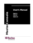
1
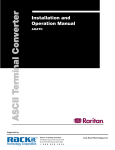
User’s Manual
MCC4, MCC8, MCC16
MCC4R, MCC8R, MCC16R
MCC8RD, MCC16RD
User’s Manual
MCC4, MCC8, MCC16
MCC4R, MCC8R, MCC16R
MCC8RD, MCC16RD
Copyright © 1999
Raritan Computer, Inc.
Ver. 0C, AUG, 2000
Raritan Computer, Inc.
400 Cottontail Lane
Somerset, NJ 08873
U.S.A.
Tel. 1-732-764-8886
Fax 1-732-764-8887
E-mail [email protected]
http://www.raritan.com
Raritan Computer Europe, B.V.
Eglantierbaan 16
2908 LV Capelle aan den IJssel
The Netherlands
Tel. 31-10-284-4053
Fax 31-10-284-4049
E-mail [email protected]
http://www.raritan.com
Raritan Computer Japan, Inc.
Kuga Building 7F, 11-6
Kuramae 4-chome Taitoo-Ku
Tokyo 111-0051, Japan
Tel. 81-3-5833-6360
Fax 81-3-5833-6336
Email [email protected]
http://www.raritan.com
Raritan Computer Taiwan, Inc.
5F,121,Lane 235,Pao-Chiao Rd,
Hsin-Tien City,Taipei Hsien
Taiwan,ROC
Tel. 886-2-8919-1333
Fax 886-2-8919-1338
E-mail:[email protected]
http://www.raritan.com
FCC Information
This equipment has been tested and found to comply with the limits for a Class
A digital device, pursuant to Part 15 of the FCC Rules. These limits are
designed to provide reasonable protection against harmful interference in a
commercial installation. This equipment generates, uses and can radiate radio
frequency energy and, if not installed and used in accordance with the instructions, may cause harmful interference to radio communications. Operation of
this equipment in a residential environment may cause harmful interference.
Product names mentioned in this document are trademarks or registered trade4
marks of their respective companies. MasterConsole MX , MasterConsole, and
their respective logos are registered trademarks of Raritan Computer, Inc. PS/2,
RS/6000, and PC/AT are registered trademarks of the International Business
Machines Corporation. Mac is a registered trademark of Apple Computer, Inc.
Sun is a registered trademark of Sun Microsystems. Alpha is a registered trademark of Digital Equipment Corporation. HP9000 is a registered trademark of
Hewlett Packard. SGI is a registered trademark of Silicon Graphics, Inc.
Japanese Approvals
Table of Contents
FCC INFORMATION
I
TABLE OF CONTENTS
II
TABLE OF FIGURES
III
WELCOME
1
OVERVIEW
1
FEATURES
1
ONE-TIER AND TWO-TIER CONFIGURATIONS
2
GETTING STARTED
3
ONE-TIER CONFIGURATION
4
INSTALLING MASTERCONSOLE II (ONE-TIER)
4
CONFIGURING MASTERCONSOLE II (ONE-TIER)
6
ASSIGNING NAMES AND SCAN RATES (ONE-TIER)
8
USING MASTERCONSOLE II SECURITY FEATURE (ONE-TIER)
10
Passwords
10
Turning Security on/off and Changing Passwords:
10
OPERATING MASTERCONSOLE II
USING ON-SCREEN USER INTERFACE (ONE-TIER)
12
Selecting a Computer
12
Setting AutoScan
14
OPERATING MASTERCONSOLE II
USING FRONT PANEL BUTTONS (ONE-TIER)
14
TWO-TIER CONFIGURATION
16
INSTALLING MASTERCONSOLE II (TWO-TIER)
16
Install Base Unit (First-Tier) MasterConsole II
16
Connect Second-Tier MasterConsole(s) to the Base Unit
17
Connect Computers to Second-Tier MasterConsole(s)
18
CONFIGURING THE BASE MASTERCONSOLE II (TWO-TIER)
19
ASSIGNING NAMES AND SCAN RATES (TWO-TIER)
21
USING THE MASTERCONSOLE II SECURITY FEATURES (TWO-TIER)
23
OPERATING MASTERCONSOLE II (TWO-TIER)
23
Selecting a Computer
23
REMOTE ACCESS USING CAT5 REACH
27
APPENDICES
28
SYSTEM DEFAULT SETTINGS
28
ON-SCREEN USER INTERFACE FUNCTION KEYS
29
MASTERCONSOLE CONFIGURATIONS AND
PROGRAMMING MASTERCONSOLE II AT POWER UP
30
MasterConsole II product Design Background and Considerations
30
Programming MasterConsole II
30
MASTERCONSOLE II CONFIGURATION DIAGRAMS
31
GLOSSARY
34
TROUBLESHOOTING
38
SPECIFICATIONS
41
Main Unit
41
Universal Cable Kits
42
Accessories
42
Remote Access Kit
42
TABLE OF FIGURES
FIGURE 1. ONE-TIER CONFIGURATION
2
FIGURE 2. TWO-TIER CONFIGURATION (WITH OPTIONAL REMOTE ACCESS)
2
FIGURE 3. MASTERCONSOLE II BACK PANEL
4
FIGURE 4. ONE-TIER CONFIGURATION CABLING DETAILS
5
FIGURE 5. CABLE ADAPTERS TO CONVERT PS/2 TO AT
5
FIGURE 6. MASTERCONSOLE II FRONT PANEL
6
FIGURE 7. MASTERCONSOLE II FRONT PANEL (CHANNEL LIGHTS)
6
FIGURE 8. CONFIGURATION MENU
6
FIGURE 9. EDIT NAMES AND SCAN RATE MENU (ONE-TIER)
9
FIGURE 10. ADMINISTRATION MENU
11
FIGURE 11. SELECTION MENU (ONE-TIER, SORTED BY CHANNEL ID)
12
FIGURE 12. TWO-TIER CONFIGURATION (WITH OPTIONAL REMOTE ACCESS KIT)
16
FIGURE 13. TWO-TIER CONFIGURATION CABLING DETAILS
17
FIGURE 14. CONFIGURATION MENU (TWO-TIER)
19
FIGURE 15. DEVICE TYPES
20
FIGURE 16. DEVICE FIELD
20
FIGURE 17. DEFAULT MASTERCONSOLE II CHANNEL IDS AND NAMES
21
FIGURE 18. EDIT NAMES AND SCAN RATE MENU (BASE MASTERCONSOLE II)
22
FIGURE 19. EDIT NAMES AND SCAN RATE MENU (SECOND-TIER MCC8)
23
FIGURE 20. SELECTION MENU (TWO-TIER, BASE MASTERCONSOLE II)
25
FIGURE 21. SELECTION MENU (TWO-TIER, SECOND TIER)
26
FIGURE 22. REMOTE ACCESS WITH CAT5 REACH
27
FIGURE 23. TWO-TIER CONFIGURATION WITH SATELLITE UNIT
27
FIGURE 24. BASIC ONE-TIER CONFIGURATIONS
31
FIGURE 25. ONE-TIER WITH REMOTE ACCESS KIT
31
FIGURE 26. TWO-TIER CONFIGURATION OF UP TO 256 COMPUTERS
32
FIGURE 27. TWO-TIER CONFIGURATION WITH MASTERCONSOLE P MODEL
32
FIGURE 28. TWO-TIER CONFIGURATION WITH SATELLITE UNIT
33
1
Welcome
Overview
Raritan's keyboard/video/mouse (KVM) switches are engineered to provide reliable, cost-effective, central control of multiple computers. This
eliminates the cost and clutter of unnecessary equipment, reclaims
space, and improves productivity for a host of applications.
MasterConsole II enables control of any mix of 2 to 256 computers
from a single keyboard, monitor, and mouse. MasterConsole II user
interface provides simple on-screen control and system management.
Raritan's unique emulation technology dedicates a keyboard/mouse
emulator for each computer to ensure that each computer always 'sees'
its own keyboard and mouse. This means smooth, flawless switching
and operation, even when computers are running the most demanding
operating systems.
Features
· Models for 4, 8, or 16 computers
· Mix any brand PCs, Macs, Suns, Alphas, RS/6000s, HP9000s, SGIs
· “Keep-alive” emulation ensures non-stop computer operation in the
event of power loss to the switch
· High resolution video-1600x1280
· Tangle-proof, double-shielded coaxial cable from 6.5, to 30 feet
· On-screen user interface for simple control and system management
· Assign meaningful names to computers for quick identification and
selection
· Operate with front panel buttons or hot-keys with on-screen menus
· AutoSkip function to bypass inactive channels
· AutoScan computers at variable rates
· Password Security to ensure authorized access to computers
· Optional Dual Remote access capability with Cat5 Reach
· Compatible with MasterView ready MasterConsole P Models (MCPn)
4
· Cascade from a multi-user MasterConsole MX
· One year warranty for parts and labor
2
One-Tier and Two-Tier Configurations
MasterConsole II can be configured in one or two tiers, depending on the
number of computers you want to control. In a one-tier configuration,
only computers are connected to a single MasterConsole II unit. See
Figure 1. In a two-tier configuration, either a computer or another
MasterConsole unit is connected to each channel of the base
MasterConsole II unit. See Figure 2.
Figure 1. One-Tier Configuration
Figure 2. Two-Tier Configuration (With optional Remote Access)
3
Getting Started
MasterConsole II is designed for quick, easy installation and operation.
Follow the steps for either one-tier or two-tier configuration to be up and
running within minutes:
1.
Install MasterConsole II (connect computers).
2.
Configure MasterConsole II.
3.
Assign computer names and set channel-specific Scan
Rates for attached computers.
4.
Turn ON security and change passwords if you want to
restrict access to computers connected to MasterConsole II.
5.
Operate using On-Screen User Interface or front panel buttons.
6.
Install optional Cat5 Reach for remote console or satellite unit.
Quick-Start Operation
After you connect computers to your MasterConsole II
you may wish to explore MasterConsole II operation
with the default names and parameters.
You may operate using the front panel buttons and/or
the On-Screen User Interface. To activate On-Screen
User Interface, press the <ScrollLock>> key twice
rapidly. The Selection Menu will appear. To select a
computer, use the <Ï>/<Ð> keys to highlight the
desired channel (computer) and press <Enter>or
press the desired computer's Key number (located in
the left-hand column). To select another computer,
use front panel buttons or re-activate the On-Screen
User Interface.
4
One-Tier Configuration
Installing MasterConsole II (One-Tier)
1.
Shut down and power off all computers to be connected to
MasterConsole II.
2.
Plug a keyboard, monitor, and mouse into the keyboard, monitor, and mouse ports on the MasterConsole II back panel. See
Figure 3 and Figure 4.
3.
Power ON the MasterConsole II unit.
4.
Using a universal cable kit (CCPnnU), plug the 25-pin connector
into one of the numbered channels on the MasterConsole II back
panel.
5.
Plug the cable's other connectors into the computer's keyboard,
monitor, and mouse ports. Use supplied adapters for AT style
PCs. See Figure 5.
6.
Power ON the connected computer.
7.
Select the connected computer by pressing the corresponding
front panel button. Verify that the monitor attached to
MasterConsole II displays the video for the connected computer.
Use the keyboard and mouse attached to MasterConsole II to
verify that they operate the connected computer.
Note:
An amber channel light above a numbered channel button on
the MasterConsole II front panel indicates that the channel is
active; that is, a computer is connected and powered on. A
green light above a numbered channel button indicates the cur
rently displayed channel. See Figure 6 and Figure 7.
8.
Repeat Steps 4 through 7 to connect the remaining computers to
MasterConsole II.
Figure 3. MasterConsole II Back Panel
5
Figure 4. One-Tier Configuration Cabling Details
Figure 5. Cable Adapters to convert PS/2 to AT
6
Figure 6. MasterConsole II Front Panel
Figure 7. MasterConsole II Front Panel (Channel lights)
Configuring MasterConsole II (One-Tier)
The Configuration Menu is used to specify your MasterConsole II configuration and to set/change operation parameters.
1.
Activate On-Screen User Interface by pressing the hot-key
(<ScrollLock> by default) twice rapidly.
Configuration Menu
Connected: 01 PC0001
Model: MCC8 Name: MCC8
Device: . . . . . . . .
Scan: Off Set: 15 Seconds
Mode: Global
Skip: On
ID Display: 20 Seconds
Hot Key: Scroll Lock
Display Position: Menu ID
Green Mode: Off 15 Minutes
Previous Channel Key: CapLck
F1 F2 F3 F4 F5 F6 F7 Esc
Figure 8. Configuration Menu
7
2.
Press <F4> to access the Configuration Menu. See Figure 8.
· The Connected field displays the Channel ID and Name of the
currently selected computer.
· The Model field displays the model number of this
MasterConsole unit.
3.
Use the <Tab> (forward)/<Shift-Tab> (backward) keys to
highlight the desired field and make your changes as follows:
· To change Name (default is the unit’s model number): Move to
Name and type a name up to five characters. This field is used
for your identification purposes only.
· The Device field specifies the type of device connected to each
channel. The default character is ".", which indicates that the
device is a computer. In a one-tier configuration, only a computer may be connected to each channel. The Device field settings
may be changed when expanding to a two-tier configuration.
See Figure 15, page 19 for two-tier device type settings.
· To turn AutoScan ON/OFF (default is OFF): Move to Scan and
press the <Ï>/<Ð> keys to toggle. If you exit On-Screen User
Interface with AutoScan ON, MasterConsole II will scan according
to the currently set mode (Individual/Global) and scan rate.
a. a. To change the Global Scan Rate (default is 3 seconds): Move to Set and type a number from 01 to 99,
or press the <Ï>/<Ð> keys to specify the Scan Rate
(in seconds) for Global AutoScan.
b. To change AutoScan mode (default setting is
Global): Move to Mode and press the <Ï>/<Ð> keys
to toggle between Global and Individual. See page
34 for description.
· To turn AutoSkip ON/OFF (default is OFF): Move to Skip and
press the <Ï>/<Ð> keys to toggle. With AutoSkip ON, only
active channels can be selected.
· To change the ID Display time interval (default is 3 seconds):
Move to ID Display and type a number from 01 to 99, or press
the <Ï>/<Ð> keys to specify the interval (in seconds) you want
the Channel ID and Name to display when each computer is
selected. Type 99 if you want the Channel ID and Name to display continuously.
· To change the On-Screen User Interface activator (default is
<Scroll Lock>): Move to Hot Key and press the <Ï>/<Ð> keys
to select the desired key. The hot-key can only be
<ScrollLock> <NumLock>, <CapsLock>, left <Shift> or left
8
<Alt>.
· To change the Menu Display position: Move to Menu and
press <Enter>. Then press the <Ï>, <Ð>, <Í>, and <Î> keys
to move the menu vertically and horizontally to the desired
position. Then press <Esc> or <Enter>.
· To change the Channel ID display position: Move to ID and
press <Enter>. Then press the <Ï>, <Ð>, <Í>, and <Î> keys
to move the menu vertically and horizontally to the desired
position. Then press <Esc> or <Enter>.
· To turn PowerSave ON/OFF (default is OFF): Move to Green
Mode and press the <Ï>/<Ð> keys to toggle. To change the
PowerSave delay time (default is 15 minutes): Move to the
next field and type a number from 01 to 99, or press the
<Ï>/<Ð> keys to change the interval (in minutes) of inactivity
(no keyboard or mouse operation) after which the video signal
will be cut off from the monitor. This will allow a properly
equipped monitor to enter low-energy mode.
· To select Previous Channel Toggle (default is CapsLock).
This feature enables the user to toggle between the previous
and current selected channel. Press F4 to display the
Configuration menu (Figure 1) and move the cursor to the
Previous Channel Key. Use the <-> or <¯> keys to select the
key, <caps lock>, <scroll lock>, <num lock>, left <shift>, or left
<alt> to be used. This feature enables the user to switch back
to a previous channel by pressing the selected key twice rapidly. There is no need to activate the OSUI.
NOTE: Select a previous channel key that is not being used as
the current hot key activator.
4.
To exit the Configuration Menu: Press an appropriate Menu F
key to go to another menu, or press <Esc> to exit On-Screen
User Interface and return to normal computer operation. Any
changes made to the Configuration Menu are automatically
saved.
Assigning Names and Scan Rates (One-Tier)
You may assign meaningful names to quickly and easily identify and
select connected computers. By default, the channel name is PC00aa
(where aa is the channel ID number) and the Channel-Specific Scan
Rate is 3 seconds.
1.
Activate On-Screen User Interface.
9
2.
Press <F3> to access the Edit Names and Scan Rate Menu.
See Figure 9.
3.
Use the <Tab>, <Shift-Tab> or <Ï>/<Ð> keys to move the
cursor to the line you want to edit. Use <Í>/<Î> to move
within a line.
· To change the Name: Type up to 8 characters (no spaces).
· To change the Channel-Specific Scan Rate (default is 3 sec-
onds): Type a number from 00 to 99 (seconds). When the
AutoScan Mode in the Configuration Menu is set to Individual,
these Channel-Specific Scan Rates are enabled. If the
AutoScan mode is set to Global, the global value will be used.
4.
When you move to a different page or exit this Menu, you are
prompted to save your changes. Press <Y> to save.
5.
To exit the Edit Names and Scan Rate Menu: Press any
Menu F key to go to another menu, or press <Esc> to go to the
Selection Menu.
Note:
If your MasterConsole II is a 16-channel model, MCC16, use the
<Page Up>/<Page Down> keys to view the next or previous
group of eight channels.
Edit Names and Scan Rate
MC: MCC8
Page: 1 / 1
Ch. ID
Name
Scan Rate
............
................. ....................
01
PC0001
05
02
Sara
03
03
Sales-2
10
04
Bob
04
05
PC0005
06
06
PC0006
08
07
Market-4
03
08
JoePC
02
............
................. ....................
F1 F2 F3 F4 F5 F6 F7 Esc
Figure 9. Edit Names and Scan Rate Menu (One-Tier)
10
USING MASTERCONSOLE II SECURITY
FEATURE (ONE-TIER)
You can restrict access to MasterConsole II. The Administration Menu
is used to turn security on/OFF and to change the Administrator's
Password and the five authorized user passwords. Up to six passwords
can be defined - one Administration Password and five User Passwords.
Note:
If security is ON, and the system remains idle (no keyboard,
mouse, or front panel operation for a time interval set by the
user-default is 15 minutes), the next user must enter a user
password to establish access. By default, MasterConsole II
operates with security OFF.
Passwords
Only the Administrator's password provides access to the Administration
Menu, which is accessed to turn security on/off and to change passwords. If you use the security feature, be sure to record and store passwords where they will be handy to you and other authorized users.
MasterConsole II is delivered with system default passwords. They are
Admin
User 1
User 2
User 3
User 4
User 5
Password
Raritan
111
222
333
444
555
as follows:
Turning Security ON/OFF and Changing Passwords:
1.
Activate On-Screen User Interface.
2.
Press <F5> to access the Administration Password prompt.
3.
Type in the Administration Password, then press <Enter>.
· The Administration Menu will be displayed. See Figure 10.
4.
Use the <Tab> (forward)/<Shift-Tab> (backward) keys to move
11
the cursor to the desired field and make your changes as
follows:
· To turn Security ON/OFF (default is OFF): Press the <Ï>/<Ð>
keys to toggle.
· To change Security activation delay time (default is 15 minutes).
Move to the Time Out field, then type a number from 01 to 99,
or use the <Ï>/<Ð> keys to specify a time interval. If the system
will remains inactive (no keyboard or mouse operation) for this
time interval, the next user is required to enter a password to
access the MasterConsole II.
· To change the Administration Password: Move to Change
Passwords, where Admin will be highlighted. Press the
<Enter> key and type a new password (up to eight alphanumeric characters, no spaces). Press <Enter>. Confirm the
password by typing it again. Press <Enter>.
· To change a User Password, press the <Tab> key to highlight
one of the desired Users. Press <Enter>. Type a new password
(up to eight alphanumeric characters, no spaces). Press
<Enter>. Confirm the password by typing it again. Press
<Enter>. Repeat this process for the remaining four Users,
pressing the <Tab> key to move from one User field to the next.
You can specify up to five User Passwords.
· To change the type of keyboard, press the <Tab> key to highlight Language Mode field. Press <Ï>/<Ð> to select English,
German, or French.
Administration Menu
Security: On
Time Out: 15 Minutes
Change Passwords:
Admin
User3
User1 User2
User4 User5
Language Mode: English
F1 F2 F3 F4 F5 F6 F7 Esc
Figure 10. Administration Menu
12
5.
To exit the Administration Menu: Press any Menu F(function
#) key to go to another menu or press <Esc> to exit on-screen
user interface and return to normal computer operation.
Operating MasterConsole II
Using On-Screen User Interface (One-Tier)
Selecting a Computer
1.
2.
Activate On-Screen User Interface by pressing the hot-key
twice rapidly.
· AutoScan is suspended, if set.
· MasterConsole II front panel buttons are disabled.
· The Selection Menu is displayed. See Figure 11.
The Selection Menu lists channels sorted either by Channel ID
or alphabetically by Name. Default sorting is by Channel ID.
Press <F12> to toggle between Channel ID and alphabetical.
· The Selection Menu displays a maximum of eight channels at a time.
· The Status column shows each channel's activity and ChannelSpecific Scan Rate. A "+" in the first column indicates a device is
connected and powered ON, while a "-" indicates the device is
powered OFF or there is no device connected. "Snn" indicates
the Channel-Specific Scan Rate of nn seconds. (default is 3 seconds).
Selection Menu
MC: MCC8
Page: 1 / 1
Key Ch ID
Name
Status
....... ...............
............... ............
1
01
2
02
3
03
4
04
5
05
6
06
7
07
8
08
....... ...............
F1 F2 F3 F4
+S05
+S03
+S10
+S04
-S06
-S08
+S03
Market-4
+S02
JoePC
............... ............
F5 F6 F7 Esc
PC0001
Sara
Sales-2
Bob
Figure 11. Selection Menu (One-Tier, sorted by Channel ID)
13
As the computer status changes (active/inactive), the MCC
updates the Status column periodically. To enable a user to see
the new status immediately, activate the OSUI and press F8Upgrade Computer Status. The MCC will scan the channels and
update the computer status and then return to the previous
menu.
· For any inactive channel, the ID bar will display only the channel
ID and not the name field, when sorted by channel and will not
display anything when sorted by name-F12 toggle.
The non-displayed names are still available in the MCC internal
database and can be edited with the F3 function.
3.
To select a computer:
· Use the <Page Up>/<Page Down> or <Ï>/<Ð> keys to
highlight the desired computer and press <Enter>;
OR
· When the Selection Menu is sorted by Channel ID, press the
desired computer's Key number (shown in the left-hand column);
OR
· When the Selection Menu is sorted by Name (arranged
alphabetically), use the <Page Up>/<Page Down> or <Ï>/<Ð>
keys, or type the first character(s) of the desired Name to quickly
jump to the Name that most closely matches what you type. To
back up a character, press the <Backspace> key. Highlight the
desired computer, and press <Enter>.
· When you select a computer, you automatically return to
normal computer operation at the selected computer.
· The light above the selected Channel button turns from
amber to green, and the monitor displays video from the
selected computer.
· The Channel ID and Name will be displayed on the monitor for the time interval specified in the Configuration
Menu.
· Press <Home> at any time to return to the first page of
the Configuration Menu (for 16-channel or two-tier systems).
Note: See Appendix page 27 for a list of other Function Keys and how
to use them.
14
Setting AutoScan
· AutoScan activation shortcut:Activate the On-Screen User
Interface and press the F6 Function Key. The green light next to
the <Scan> button on the front panel will be ON and the unit
will scan according to the parameters set in the Configuration
Menu.
Operating MasterConsole II
Using Front Panel Buttons (One-Tier)
When the on-screen user interface is not activated, you can operate
MasterConsole II from the front panel.
The front panel has a <Scan> button, a <Skip> button, and a series of
numbered buttons used to select channels and to set the Global Scan
Rate. See Figure 6 and Figure 7.
1.
To select a computer:
· Be sure the green light next to the <Scan> button is OFF
(toggle ON/OFF).
· Press the numbered button corresponding to desired channel.
· The light above the selected Channel button turns green,
video from the selected computer displays on screen and
you may now operate the selected computer.
· The Channel ID and Name will be displayed on the
screen for the time interval specified in the Configuration
Menu.
2.
To activate AutoScan:
· Press the <Scan> button (toggle ON/OFF) The green light next
to the <Scan> button will be ON and the unit will scan according to the parameters set in the Configuration Menu. If the
AutoScan Mode is set to Individual, AutoScan will occur at the
Channel-Specific Scan Rates as defined in the Edit Names and
Scan Rate Menu.
15
3.
To change the Scan Rate:
· While AutoScan is ON, press the numbered button
corresponding to the desired Scan Rate located above the front
panel channel light to set the Global Scan Rate. If the Scan
Mode in the Configuration Menu had been previously set to
Individual, it will be reset to Global after the front panel button is
pressed.
4.
To activate AutoSkip:
· Press the <Skip> button (toggle ON/OFF). The green light next
to the Skip button will be ON and only active channels will be
selected.
16
Two-Tier Configuration
You may cascade MasterConsole II units to create a two-tier configuration. In a two-tier configuration, a mix of devices-computers and
MasterConsoles-may be connected to the channels of the first tierreferred to as the base MasterConsole II. See Figure 12.
The second-tier MasterConsole may be any combination of MasterConsole IIs,
or MasterConsole P Models, which may be banked. Only computers may be
connected to the channels of the any second-tier MasterConsole.
Figure 12. Two-Tier Configuration (With optional Remote Access Kit)
Installing MasterConsole II (Two-Tier)
Install Base Unit (First-Tier) MasterConsole II
1.
Plug the keyboard, monitor, and mouse into the keyboard, monitor, and mouse ports on the MasterConsole II back panel.
See Figure 13.
2.
Power ON the MasterConsole II base unit.
3.
Connect computers to any Channels on the base
MasterConsole II back panel.
a.
Shut down and power off all computers to be connected
to the base MasterConsole II.
17
b.
Using a Universal cable kit (CCPnnU), plug the 25-pin
connector into one of the numbered Channels on the
base MasterConsole II back panel.
c.
Plug the cable's other connectors into the computer's
keyboard, monitor, and mouse ports. Use supplied
adapters for AT style PCs. See Figure 5.
d.
Power ON the connected computer.
e.
Select the connected computer by pressing the
corresponding front panel button. Verify that the monitor
attached to MasterConsole II displays the video for the
connected computer. Use the keyboard and mouse
attached to the base MasterConsole II to verify that
they operate the connected computer.
f.
Repeat Steps 3.a through 3.e to connect additional
Figure 13. Two-Tier Configuration Cabling Details
computers to the base MasterConsole II.
Connect Second-Tier MasterConsole(s) to the Base Unit
4.
Connect MasterConsole(s) to any Channel(s) of the base
MasterConsole II.
18
a.
Using a Universal cable kit (CCPnnU), plug the 25-pin
connector into one of the numbered Channels on the
base MasterConsole II back panel.
b.
Plug the cable's other connectors into the Keyboard,
Monitor, and Mouse ports of the second-tier
MasterConsole II or MasterConsole P Model.
c.
Power on the MasterConsole unit according to the follow-
Note: All second-tier MasterConsole P Models must be MasterView
ready. To determine if your P Model does have this feature,
check the white label on the bottom of the unit *. This label
shows the unit's level and style of firmware: MDSP-nnn. If it is
MDSP-1AC or higher (MDSP-1AD, etc.), the unit is MasterView
ready. If not, you need to upgrade. Call Raritan Technical
Support for details.
ing instructions:
· IMPORTANT: For MasterConsole II, the unit must be
programmed as a second-tier unit. (The default setting
is first-tier) To program any MasterConsole II as a second-tier unit, power ON while pressing the Channel #2
button on the front panel and hold for 3 seconds. When
the unit is programmed as a second-tier unit, the LED
on the far right of the unit's front panel (2ND) will be lit
continuously. Note: Any unit can be re-programmed to
be a first-tier unit by pressing the Channel #1 button on
the front panel during a subsequent power ON process.
· For MasterConsole P Model: Turn the power switch on.
d.
Repeat steps 4a through 4c to connect additional secondtier MasterConsole units to the base MasterConsole II.
e.
For second-tier units located more than 30 feet away
from the base unit, see Remote Access Using Cat5
Reach, page 25.
Connect Computers to Second-Tier MasterConsole(s)
5.
Connect computers to the channels of second-tier
MasterConsole(s).
· Follow Steps 3a through 3f to connect the computers to each
second-tier MasterConsole II.
· For MasterConsole P Models, follow installation instructions in
the P Model manual.
19
Configuring the Base MasterConsole II
(Two-Tier)
The Configuration Menu is used to specify your base MasterConsole II
configuration and to set/change parameters for operation.
See Figure 14
1.
Activate On-Screen User Interface by pressing the hot-key
(<Scroll-Lock> by default) twice rapidly.
2.
Press <F4> to access the Configuration Menu.
· The Connected field displays the Channel ID and Name of the
currently selected computer.
· The Model field displays the model number of this
MasterConsole unit (MCCn).
3.
Use the <Tab> (forward)/<Shift-Tab> (backward) keys to select
the desired field and make your change as follows:
· To change Name (default is the unit's model number): Move to
Name and type a name up to five characters. This field is usedfor your identification purposes only.
· The Device field specifies the type of device computer or
Configuration Menu
Connected: 01 PC0001
Model: MCC8 Name: MCC8
Device: . . . . . . .
Scan: Off Set: 15 Seconds
Mode: Global
Skip: On
ID Display: 20 Seconds
Hot Key: Scroll Lock
Display Position: Menu ID
Green Mode: Off 15 Minutes
Previous Channel Key: CapsLck
F1 F2 F3 F4 F5 F6 F7 Esc
Figure 14. Configuration Menu (Two-Tier)
20
MasterConsole connected to each channel of the base
MasterConsole II unit. <Tab> to the Device field. You must
specify the device for each channel .See Figure 15.
The Device field consists of a sequence of characters equal to
the channel capacity of the base unit. The leftmost character
corresponds to the unit's channel 1, while the rightmost character corresponds to the highest channel number.
.(dot)
=
computer (default)
For non-computers, define the Device as follows:
a
=
MCP2
b
=
MCP4
c
=
MCP8
d
=
MCP16
x
=
MCC4, MCS4, MCX4
y
=
MCC8, MCS8, MCX8
z
=
MCC16, MCX16
Figure 15. Device Types
Channel 8
Channel 6
Channel 1
Device: y . . . . c . .
Figure 16. Device Field
For example, in Figure 16, the y . . . . c . . Device field indicates the following: an 8-channel MasterConsole II MCC8 model is connected to the
first channel on the base MasterConsole II, an 8-channel MasterConsole
P Model is connected to the sixth channel, and computers are connected
(or to be connected) to all other channels.
Note: If you specify a MasterConsole P Model, a pop-up box will
prompt for banking information.
See One-Tier Configuration for instructions on setting/changing other
operational parameters (AutoScan, AutoSkip, ID Display, hot-key, Menu
Display, PowerSave).
21
Assigning Names and Scan Rates (Two-Tier)
When you specify non-computer devices (MasterConsole units) connected to base MasterConsole II channels, these devices are automatically assigned default names in the base MasterConsole II Selection
Menu. In addition, since computers can be connected to each channel
of a second-tier MasterConsole, a page is automatically created for
each second-tier MasterConsole in the Selection Menu, listing Channel
IDs with default names for each channel. These names may be
changed using the Edit Names and Scan Rate Menu. See Figure 12b
and Figure 12c.
The following are the MasterConsole II default Channel ID and Names
for connected devices in a two-tier configuration.
To change Names and/or Channel-Specific Scan Rates:
1.
Activate On-Screen User Interface.
2.
Press <F3> to access the Edit Names and Scan Rate Menu.
See Figure 18 and Figure 19.
Base MasterConsole II
Connected Devices
computer
Channel ID
aa
Default Name
PC00aa*
MasterConsole II
aa
/MCCaa*
MasterConsole MCPn
aa
/MCPaa*
* where aa= Channel # of the base MCCn.
Second Tier
Computers Connected To
Channel ID
Default Name
MasterConsole II
aa.bb
PCaabb
where aa= Channel # of the base MCCn;
and bb= Channel # of the second-tier MasterConsole II
MasterConsole P Model
aa.Bb-cc
PCaaBbcc
where aa= Channel # of the base MCCn,and b= Bank #
and cc= Channel # of the second-tier MCPn
Figure 17. Default MasterConsole II Channel IDs and Names
22
3.
Use the <Tab>, <Shift-Tab> or <Ï>/<Ð> keys to move the
cursor to the line you want to edit. Use <Í>/<Î> to move
within a line.
Note: Since you have specified a two-tier configuration, use the <Page
Up>/<Page Down> keys to view the next or previous group of
up to eight channels.
· To change the Name of a second tier MasterConsole Device
in the base unit channel list: Type up to seven alphanumeric
characters (no spaces). The "/" (backslash) first character cannot be changed.
· To change the Name of any computer connected to either the
base unit or second-tier MasterConsole, type up to eight
alphanumeric characters (no spaces).
· To change the Channel-Specific Scan Rate for any highlighted
channel (default is 3 seconds): Type a number from 00 to 99 (in
seconds). When the AutoScan Mode in the Configuration Menu
is set to Individual, these Channel-Specific Scan Rates are
enabled. If the AutoScan mode is set to Global, the global scan
rate will be used.
Edit Names and Scan Rate
MC: MCX8
Page: 1 / 3
Ch. ID
Name
Scan Rate
............
................. ....................
01
/MCS01
08
02
PC0002
03
03
Market-3
10
04
Jen
04
05
Vicki
06
06
/MCP06
05
07
PC0007
03
08
PC0008
02
............
................. ....................
F1 F2 F3 F4 F5 F6 F7 Esc
Figure 18. Edit Names and Scan Rate Menu (Base MasterConsole II)
23
Edit Names and Scan Rate
MC: MCS01
Page: 2 / 3
Ch. ID
Name
Scan Rate
............
................. ....................
01.01
PC0101
05
01.02
Sara
03
01.03
Sales-2
10
01.04
Bob
04
01.05
PC0105
06
01.06
PC0106
08
01.07
Market-4
03
01.08
JoePC
02
............
................. ....................
F1 F2 F3 F4 F5 F6 F7 Esc
Figure 19. Edit Names and Scan Rate Menu (Second-Tier MCC8)
4.
When you move to a different page or exit this Menu, you are
prompted to save your changes. Press <Y> to save.
5.
To exit the Edit Names and Scan Rate Menu: Press any
Menu F key to go to another menu, or press <Esc> to go to
the Selection Menu.
Using MasterConsole II’s Security Feature
(Two-Tier)
Follow instructions for Security in
Using MasterConsole II’s Security Feature (One-Tier), page 9.
Important: You must use the On-Screen User Interface to operate
a two-tier configuration.
There is no front panel opertion available.
Operating MasterConsole II (Two-Tier)
Selecting a Computer
1.
1. Activate On-Screen User Interface.
24
· AutoScan is suspended, if set.
· MasterConsole II front panel buttons are disabled.
· The Selection Menu is displayed. See Figure 20 and
Figure 21
2.
The Selection Menu lists channels sorted either by Channel ID
or alphabetically by Name. Default sorting is by Channel ID.
Press <F12> to toggle.
· The Selection Menu displays a maximum of eight
channels at a time.
· The Status column shows each channel's activity and
Channel-Specific Scan Rate. A “+”in the base unit's
Selection Menu indicates the device is connected and
powered ON, while a “–” indicates the device is powered
OFF, or there is no device connected. A “.” in the Status
column of the second-tier Selection Menu indicates that
the status of the computer is undetermined. Snn indicates the individual Scan Rate of nn seconds.
As the computer status changes (active/inactive), the
MCC updates the Status column periodically. To enable a
user to see the new status immediately, activate the OSUI
and press F8-Upgrade Computer Status. The MCC will
scan the channels and update the computer status and
then return to the previous menu.
· For any inactive channel, the ID bar will display only the
channel ID and not the name field, when sorted by channel and will not display anything when sorted by nameF12 toggle
The non-displayed names are still available in the MCC
internal database and can be edited with the F3 function.
3.
To select a computer:
· Use the <Page Up>/<Page Down> or <Ï>/<Ð> keys to scroll
to the desired computer and press <Enter>;
OR
· When the Selection Menu is sorted by Channel ID, press the
desired computer's Key number (in the left-hand column);
25
OR
· When the Selection Menu is sorted by Name, use the <Page
Up>/<Page Down> or <Ï>/<Ð> keys, or type the first
character(s) of the desired Name to quickly jump to a Name
that most closely matches what you type. To back up a
character, press the <Backspace> key. Highlight the desired
computer, and press <Enter>.
· When you select a computer, you automatically return to
normal computer operation at the selected computer.
· The light above the selected Channel button turns green,
and the monitor displays video from the selected computer.
· The Channel ID and Name will display on the monitor for
the time interval specified in the Configuration Menu.
· Press <Home> at any time to return to the first channel on the
first page of the Selection Menu. Press <End> at any time to
advance to the last channel on the last page of the Selection
Menu.
Selection Menu
MC: MCC8
Page: 1 / 3
Key Ch ID
Name
Status
....... ...............
............... ............
1
01
/MCC01
+S08
2
02
PC0002
+S03
3
03
Market-3
+S10
4
04
Jen
+S04
5
05
Vicki
+S06
6
06
/MCP06
+S08
7
07
PC0007
+S03
8
08
-S02
...... ..............
............... ..............
F1 F2 F3 F4 F5 F6 F7 Esc
Figure 20. Selection Menu (Two-Tier, Base MasterConsole II)
26
Selection Menu
MC: MCC01
Page: 2 / 3
Key Ch ID
Name
Status
....... ...............
............... ............
1
01. 01
2
01. 02
3
01. 03
4
01. 04
5
01. 05
6
01. 06
7
01. 07
8
01. 08
....... ...............
F1 F2 F3 F4
PC0101
.S05
Sara
.S03
Sales-2
.S10
Bob
.S04
PC0005
.S06
PC0006
.S08
Market-4
.S03
JoePC
.S02
............... .............
F5 F6 F7 Esc
Figure 21. Selection Menu (Two-Tier, Second Tier)
27
Remote Access Using Cat5 Reach
Raritan's Cat5 Reach can be used to extend the user console up to 650
feet away. Please see the Cat5 Reach manual for installation procedure.
The MasterConsole II with Cat5 Reach provides:
· Dual Remote User Console:: Remote access point to a base
MasterConsole II, plus a local user console. See Figure 22.
· Satellite Unit:: Second-tier MasterConsole located more than
30 feet from the base unit. See Figure 23.
Figure 22. Remote Access with Cat5 Reach
Figure 23. Two-Tier Configuration with Satellite Unit
28
Appendices
System Default Settings
Administration Password
raritan(case sensitive)
AutoScan
OFF
AutoScan mode
Global
AutoSkip
OFF
Channel-Specific Scan Rate
3 seconds
Device
“.” (computer devices)
Global Scan Rate
3 seconds
Hot Key
<ScrollLock> <ScrollLock>
ID Display Interval
3 seconds
MasterConsole II unit configuration
First tier
PowerSave
OFF
PowerSave delay time (Green Mode) 15 minutes
Remote Time Out interval
3 seconds
Security
OFF
Security activation delay time
15 minutes
Selection Menu sorting
Channel ID
User password
User 1
111
User 2
222
User 3
333
User 4
444
29
On-Screen User Interface Function Keys
Use the following Function Keys while using On-Screen User Interface:
Press...
when you want to...
<F1>
go to the Help Menu; get a list of all the Function keys.
<F2>
go to the Selection Menu; view the list of channels or
select a channel.
<F3>
go to the Edit Names and Scan Rate Menu; change
channel Names or Individual Scan Rates.
<F4>
go to the Configuration Menu; change operating
parameters (On-Screen User Interface, Menu position, ID
position, Global / Individual Scanning, AutoScan
OFF/ON, Scan Rate, AutoSkip OFF/ON, Hot Key,
duration of ID display).
<F5>
go to the Administration Menu; turn Security ON/OFF,
change User Passwords.
<F6>
exit On-Screen User Interface and turn ON AutoScan.
<Alt>+<F6>
exit On-Screen User Interface and turn OFF AutoScan.
<F7>
exit On-Screen User Interface and turn ON AutoSkip.
<Alt>+<F7>
exit On-Screen User Interface and turn OFF AutoSkip.
<F12>
toggle Selection Menu sorting (by Name or Channel ID).
<Esc>
exit On-Screen User Interface and return to normal
computer operation at the last channel selected. If SCAN
is set ON, the system will AutoScan according to
parameters set in the Configuration Menu.
30
MasterConsole Configurations and
Programming MasterConsole II at Power Up
MasterConsole II Product Design Background and
Considerations
· User connection and operation of MasterConsole II is through the
unit's local KVM port (marked Keyboard, Monitor, Mouse - Din
6F,HD15F, Din 6F) on the back panel of each MasterConsole II.
· For operation,a console-keyboard, monitor and mouse-plugs into the
local KVM port. MasterConsole II includes front panel buttons as well
as an integrated On-Screen User Interface for switching and other
operations.
· The On-Screen User Interface is activated through a console keyboard and facilitates operation of MasterConsole II with on-screen
menus and commands.
· In a one-tier configuration, the console operates the all connected
computers. The KVM port is called first-tier ports, which means that
they have an active On-Screen User Interface for console operation.
· In a two-tier configuration, one or more MasterConsole II second-
tier units are cascaded from the base unit. This is accomplished by
connecting MasterConsole II computer cable from the base unit to the
KVM port of the second-tier unit. The base unit's local KVM port and
remote access port are first-tier ports with an active On-Screen User
Interface; and the base unit's on-screen menus include the names of
all the computers accessible from the base unit's console. This way,
the base unit's console can access and operate all MasterConsole II
units and all connected computers. For proper operation, the user
must see only the base units On-Screen User Interface menus from
the base unit console. To accomplish this, the On-Screen User
Interface at the port by which the second-tier unit is connected must
be deactivated, so that the base unit console can access and operate
all connected computers. A port with a deactivated On-Screen User
Interface and is called a second-tier port.
Programming MasterConsole II
Each MasterConsole II is programmed at the factory as a base tier unit.
To modify the factory setting, a MasterConsole II unit can be programmed as a second-tier unit by holding down the #2 button on the
front panel at power up for a minimum of 3 seconds.
31
MasterConsole II Configuration Diagrams
For more information on cabling details see Figure 4, 5, and 13.
Basic MasterConsole II One-Tier Configurations
CCPxU
CCPxU
CCPxU
MCC8
MCC4
M C C 16
M asterC onsole II B asic C onfigurations of
2 to 16 C om puters
Figure 24. Basic One-Tier Configurations
MasterConsole II Two-Tier Configuration with Remote Access Kit
C C P xU
O ne-Tier C onfiguration w ith a
R em ote and a Local A ccesses
M C C 16
C C P xU
C at5
R em o te
KVM
M o d u le
C at5 L o cal
KVM
M o d u le
UTP
C a b le
C a t5
et
6 5 0 fe
U p to
Figure 25. One-Tier with Remote Access Kit
32
MasterConsole II Two-Tier Configuration
CCPxU
Cable
M C C 16
CCPxU
CCPxU
M C C 16
M C C 16
CCPxU
M C C 16
CCPxU Cable
User Port
M C C 16
Channel Ports
M asterC onsole II Tw o-Tier
C onfiguration for U p to 256
C om puters
Figure 26. Two-Tier Configuration of up to 256 Computers
MasterConsole II Two-Tier Configuration with MasterConsole P Model
CCPxU
Cable
CCPxU
M C C 16
M C P 16
CCPxU
CCPxU Cable
M C C 16
M asterC onsole II Tw o-Tier
C onfiguration w ith
M asterC onsole P M odel
Figure 27. Two-Tier Configuration with MasterConsole P Model
33
MasterConsole II Two-Tier Configuration with Satellite Unit
CCPxU
MCC8
CCPxU
Satellite U nit
Second-Tier
65
0f
e
et
C at5 Local
KVM
M odule
eU
p
to
CCPxU
Cable
Ca
t5
Ca
bl
CCPxU
UT
P
M C C 16
M C P 16
C at5 R em ote
K V M M odule
CCPxU
CCPxU Cable
M C C 16
M asterC onsole II Tw o-Tier
C onfiguration w ith Satellite U nit
Figure 28. Two-Tier Configuration with Satellite Unit
34
Glossary
· Administration Menu
Used to restrict access to MasterConsole II; toggle Security
ON/OFF and to change Administrator’s Password and up to five
User Passwords.
· Administration Password
The only Password with access to the Administration Menu,
through the Administration password prompt.
· AutoScan
When activated, MasterConsole II automatically cycles through
channels, displaying each computer’s video for a specified
period.
· AutoSkip
When activated, channel selection is restricted to active
channels.
· Base Unit
MasterConsole II unit to which devices (computers and / or
other MasterConsoles) are connected in a two-tier
configuration.
· Channel
The 25-pin connector by which a device is connected to
MasterConsole II.
· Active: A channel is active when a powered ON device is
connected to it.
· Inactive: A channel is inactive when there is no device
connected to it, or if the connected device is powered OFF.
· Channel ID
The specific Channel number to which a device is connected.
35
· Configuration
· One-Tier: Computers are connected to a single
MasterConsole II unit.
· Two-Tier: A mix of devices (computers and MasterConsole
units) are connected to a base MasterConsole unit.
· Configuration Menu
Used to specify MasterConsole II configuration and operation
parameters.
· Device
A computer or a MasterConsole unit connected to a
MasterConsole II channel.
· Device Field
In the Configuration Menu, specifies the type of device connected to each channel of a base MasterConsole II unit.
· Edit Names and Scan Rate Menu
Used to assign meaningful Names to each channel and set
Channel-Specific Scan Rates.
· Green Mode
A field in the Configuration Menu used to toggle the PowerSave
feature ON/OFF.
· Hot Key
Used to activate On-Screen User Interface. (To activate OnScreen User Interface, press the hot-key twice rapidly).
· ID Display
The display shown on the monitor to identify the currently
selected channel.
· Key
Left-hand column in the Selection Menu; lists the key numbers
(a sequence of numbers) for the channels listed on that page.
To quickly select a channel, press its Key number when the
Selection Menu is displayed.
36
· KVM Port
The Keyboard, Monitor, and Mouse connectors on the back of
the MasterConsole II unit.
· Menu
An On-Screen User Interface display.
· Menu F Keys
Function keys used to access On-Screen User Interface menus
while On-Screen User Interface is activated.
· Mode
Field in the Configuration Menu; can be set to either Global or
Individual. See also Scan Rate.
· Name
A user-assigned label (up to eight characters) for a device
connected to a MasterConsole II channel.
· On-Screen User Interface (OSUI)
Series of Menus displayed on the monitor that can be used,
through keystrokes, to operate MasterConsole II. All keystrokes
are captured and interpreted as MasterConsole II commands.
· PowerSave
Allows a properly equipped monitor to operate in low-energy
mode.
· Remote Console
Keyboard, monitor, and mouse plugged into the Remote access
kit.
· Cat5 Remote KVM Module
Optional Remote Unit that connects to the MasterConsole II to
provide additional access to connected computers up to 650'
away using Cat5 UTP Cable.
· Cat5 Remote KVM Port
The Keyboard, Monitor, and Mouse ports on the back of the
Cat5 Remote KVM Module unit.
37
· Satellite Unit
Second-tier MasterConsole II located more than 30 feet from
the base unit and connected through its Remote Access Kit.
· Scan
Front panel button and On-Screen User Interface function used
to activate AutoScan.
· Scan Rate
The duration (in seconds) a channel’s computer is to remain
displayed on the monitor when AutoScan is activated.
· Global Scan Rate: Scan rate is the same for all computers, if
the Mode field in the Configuration Menu is set to Global.
· Channel-Specific (Individual) Scan Rate:: Scan rate specified
for each computer during the Scan cycle, if the Mode field in the
Configuration Menu is set to Individual. Channel-specific scan
rates can be set in the Edit Names and Scan Rate Menu.
· Security
When activated, and the system remains idle for a period of
time, the next user must enter an authorized User Password to
establish access.
· Selection Menu
Used to select a computer.
· Sorting
Order of the channels listed in Selection Menu; either by
Channel ID or by Name.
· Time Out
Is the length of time that the system can remain idle (that is,
since the last keyboard/mouse or front panel operation) before
the next user must enter an authorized User Password to
establish access.
· User Password
Enables access to the system after Time Out.
38
Troubleshooting
1. No power.
a. Check power cord.
b. Make sure power switch is turned ON.
c. Check cable connection from PC to MasterConsole II.
2. No video display for one or all computers.
a. Check video cable’s connection to the PC.
b. Check the monitor and PC: Turn off power to
MasterConsole and the PCs. Connect the monitor to
the PC directly, boot the PC, and make sure the monitor
has the proper display. If it does not, the problem is
either with your PC, or the monitor is not compatible
with your PC. If it does display, continue to
Troubleshooting #3.
3. The monitor cannot correctly display the video output from
some of the PCs.
a. The monitor probably does not match the video outputs.
If the monitor is a single mode type VGA, all PCs must
have the same type of video output.
b. (Note: this problem occurs most often with some IBM
PS/2s and IBM 63xx, 85xx, and 95xx monitors.) The
intelligent type display card outputs video signals based
on the monitor ID-pin setting in the connector of the
monitor cable. If the ID-pin setting is correct, the monitor at MasterConsole may have no display, become
monochrome instead of color, or become unstable. If
this is the case, you will need to provide a proper IDpattern to the display card. Call Raritan Computer for
help if necessary.
39
4. All PCs powered up without keyboard error, but the keyboard at
MasterConsole II has no control (cannot input to any PC).
a. Make sure the keyboard is connected firmly into
MasterConsole II. Disconnect and reconnect keyboard.
b. Replace keyboard. (MasterConsole II allows hot re-connection of keyboard at its Keyboard port.)
c. In a two-tier configuration, check that the MasterConsole
II with the keyboard connected is the base unit.
5. Repeated “KB ERROR" at power-up of PC.
a. The keyboard cable from the PC to MasterConsole II is
loose. Secure the connection and power up the PC
again.
b. If the problem occurs after MasterConsole II has been
installed for a period of time, and occurs on PCs that
have previously worked with MasterConsole II , then
some components are out of order. Verify that the PC
works with the keyboard when connected directly. Then
contact your dealer or Raritan Computer for service.
6. After a period of trouble-free operation, the keyboard attached
to MasterConsole II locks (unable to input keystrokes) when a
particular PC is selected, but works normally when other PCs
are selected.
a. The most likely cause of the problem is either a voltage
"spike" (increase) or a "brown out" (decrease) in the
power supply, which would cause the microprocessors
in MasterConsole II to malfunction. A short-term solution
to the problem is to try to recover operation by turning
the MasterConsole II power switch off and on. Then, if
necessary, restart all PCs. The long-term method of
avoiding this problem is to power MasterConsole from a
UPS.
b. Check keyboard connection.
40
7. Repeated "MOUSE INSTALLATION FAILURE" at power-up of PC.
a. The mouse cable from the PC to MasterConsole II is
loose. Secure the connection and power up again.
b. If the problem only occurs to new PCs which are being
added to the system, the firmware in the KVM
(MasterConsole II internal mouse emulator) may need
to be upgraded to a later version to be compatible with
newer PCs. Contact your dealer or Raritan Computer
for Service.
8. After a period of trouble-free operation, the mouse attached to
MasterConsole II locks (unable to control mouse functions)
when a particular PC is selected, but works normally when
other PCs are selected.
a. Try to identify if the problem is originating from the PC
by reconnecting the PC to a different channel with a different cable. Then power up the PC. If the problem is
not with the cable or with the specific channel, then
connect the mouse directly to the PC. If the problem
persists, then the PC's mouse port is out of order.
Otherwise, contact your dealer or Raritan Computer.
b. If the problem occurs after MasterConsole II has been
installed for a period of time, and occurs to PCs that
have previously worked with MasterConsole II , then
some components are out of order. Contact your dealer
or Raritan Computer for service.
9. Unit does not operate in On-Screen User Interface.
a. Replace keyboard. On-Screen User Interface works
only with PS/2 or extended AT style keyboards.
10. Unable to select channel.
a. Scan function is active; press the Scan button once to
toggle Scan OFF so the light next to the button is off.
41
Specifications
Main Unit
Desktop Model
MCC4 (4–channel model)
MCC8 (8–channel model)
MCC16 (16–channel model)
Power
Rackmount Model
MCC4R (4–channel model)
MCC8R (8–channel model)
MCC16R (16–channel model)
Power
Rackmount 48 Volt DC Model
MCC8RD (8–channel model)
MCC16RD (16–channel model)
10.55”(W) x 9”(D) x 1.75”(H)
2.0 kg (4.5 lbs.)
15.4”(W) x 9”(D) x 1.75”(H)
2.8 kg (6.1 lbs.)
15.4”(W) x 9”(D) x 3.5”(H)
3.8 kg (8.4 lbs.)
115V/230V (Auto Sensing)
60 Hz / 50 Hz
0.2A/0.1A
19”(W) x 9”(D) x 1.75”(H)
3.0 kg (6.66 lbs.)
19”(W) x 9”(D) x 1.75”(H)
3.77 kg (8.37 lbs.)
19”(W) x 9”(D) x 3.5”(H)
4.8 kg (10.66 lbs.)
115V/230V (Auto Sensing)
60 Hz / 50 Hz
0.2A/0.1A
19”(W) x 9”(D) x 1.75”(H)
2.97 kg (6.6 lbs.)
19”(W) x 9”(D) x 3.5”(H)
4.52 kg (10.05 lbs.)
Power
48Volt DC +/-0.3A
3W3 male connector
Pin out A1 (G), A2 (-), A3 (+)
Operating Temp.
0–50°C (32–122°F)
42
Universal Cable Kits
For each PS/2 Computer (VGA Video, PS/2 K/B, PS/2 Mouse)
and AT Computer (VGA Video, AT K/B, Serial Mouse)
Part No.
CCP06U
CCP20U
CCP40U
CCP60U
CCP90U
Length
2’ (0.6 M)
6.5’ (2 M)
13’ (3 M)
20’ (6 M)
30’ (9 M)
Connectors
DB25(M) to HD15(M),
DB25(M) to HD15(M),
DB25(M) to HD15(M),
DB25(M) to HD15(M),
DB25(M) to HD15(M),
2x
2x
2x
2x
2x
mini-DIN6(M)
mini-DIN6(M)
mini-DIN6(M)
mini-DIN6(M)
mini-DIN6(M)
Each Universal Cable Kit comes with 2 Adapters for AT keyboard and
serial mouse: (1) DIN 6F to DIN 5M, and (1) DIN 6F to DB9F
Accessories
RMCS4 (for 4–channel model)
RMCS8 (for 8–channel model)
RMCS16 (for 16–channel model)
19” Rack Mount Bracket – 1U
19” Rack Mount Bracket – 1U
19” Rack Mount Bracket – 2U
PCE60
20’ (6 M) Extension Cable for
Keyboard, Video, and Mouse
35’ (11 M) Extension Cable for
Keyboard, Video, and Mouse
PCE110
Remote Access Kit
See Cat5 Reach Specification Sheet for complete details.
UKVM (Dual Transmitter for Category 5 UTP cable)
Dimensions
Weight
Power
User Port (local access)
Connection to PC/switch
4.3" (W) x 3.6"(D) x 1.0" (H)
108mm (W) x 91mm (D) x 23mm (H)
0.5 lbs (0.2 kg)
No external power required
6 pin k/b & mouse, HD15
Cable kit CCP06U or CCP10E included
43
URKVM (Receiver for Category 5 UTP cable)
Dimensions
4.3" (W) x 3.6"(D) x 1.0" (H)
108mm (W) x 91mm (D) x 23mm (H)
0.5 lbs (0.2 kg)
6V DC input (Adapter included)
6 pin k/b & mouse, HD15
Weight
Power
User Port (remote access)
Note: Category 5 UTP cable with RJ45 connectors must conform to
EIA/TIA T568B Category 5 wiring standard.
Note: For highest quality video at distances greater than 200',
Category 5 UTP Enhanced (350Mhz bandwidth) cable is recom
mended.
1
1
3
2
5
7
3
9
4
5
11
6
13
7
16 SECS
8
SKIP
CompuSwitch
SKIP
SCAN
s
SCAN RATE
1 SEC
3 SEC
5 SEC
7 SEC
9 SEC
1
2
3
4
5
11 SEC
13 SEC
16 SEC
7
8
URKVM
UKVM
To P C
CH AN NEL SELEC T
To P C
6
KVM Module
Por t Out
AUTO
P or t Ou t
SCAN RATE
SCAN
CompuSwitch
KVM Module
MasterConsole II
CCP06U
Lo cal KVM Po rt
Statu s
other KVM switch
Category 5
UTP cable
(not included)
Lo cal KVM Po rt
Statu s