1
PREFACE
Thank you for purchasing Pro-face’s ladder logic programing software, Pro-Control
Editor Ver. 5.0.
To ensure the safe and correct use of this product, be sure to read all related materials
carefully and keep them nearby so that you can refer to them whenever required.
NOTE
1. The copyrights to all programs and manuals included in Pro-Control Editor
Ver. 5.0 (hereinafter referred to as “this product”) are reserved by Digital
Electronics Corporation. Digital Electronics Corporation grants the use of this
product to its users as described in the “Software Licence Agreement” (included with the CD-ROM). Any violation of the abovementioned conditions is
prohibited by both Japanese and foreign regulations.
2. The contents of this manual have been thoroughly inspected. However, if you
should find any errors or omissions in this manual, please contact your local
sales representative.
3. Regardless of the above clause, Digital Electronics Corporation shall not be
held responsible for any damages, losses or third-party claims resulting from
the use of this product.
4. Differences may exist between the descriptions found in this manual and the
actual functioning of this software. Therefore, the latest information on this
software is provided in the form of data files (Readme.txt files, etc.) and/or
separate documents. Refer to these sources as well as this manual prior to use.
5. Even though the information contained in and displayed by this product may be
related to intangible or intellectual properties of Digital Electronics Corporation
or third parties, Digital Electronics Corporation shall not warrant or grant the
use of said properties to any users or other third parties. Also, Digital Electronics Corporation shall not be liable for problems related to intellectual
properties of the third party caused by using the information contained in and
displayed by this product.
© 2004 Digital Electronics Corporation. All rights reserved.
Digital Electronics Corporation, January 2004.
For information about the rights to trademarks and trade names, see “TRADEMARK RIGHTS.”
Pro-Control Editor Ver. 5.0 User Manual
1
Preface
TABLE OF CONTENTS
PREFACE .................................................................................................... 1
TRADEMARK RIGHTS ................................................................................. 7
APPLICABLE PRODUCTS ........................................................................ 8
HOW TO USE THIS MANUAL .................................................................... 9
PRODUCT USAGE PRECAUTIONS ....................................................... 10
FOR GLC2400/GLC2600 USERS ............................................................11
DOCUMENTATION CONVENTIONS ........................................................ 12
CHAPTER 1
1.1
CONTROLLER FEATURES
Operating the GLC .................................................................................... 1–1
1.1.1
Controller Feature Overview .......................................................... 1–3
1.1.2
RUN Mode .................................................................................... 1–5
1.1.3
GLC Scan Overview ...................................................................... 1–5
CHAPTER 2
VARIABLES
2.1
Variable Names .......................................................................................... 2–1
2.2
Variable Types ............................................................................................ 2–3
2.3
Accessing Variables ................................................................................... 2–7
CHAPTER 3
SYSTEM VARIABLES
3.1
System Variable List ................................................................................. 3–1
3.2
System Variable Details ............................................................................ 3–3
3.2.1
#AvgLogicTime ............................................................................... 3–3
3.2.2
#AvgScanTime ................................................................................ 3–3
3.2.3
#LogicTime ..................................................................................... 3–4
3.2.4
#ScanCount .................................................................................... 3–4
3.2.5
#ScanTime ...................................................................................... 3–5
3.2.6
#WatchdogTime .............................................................................. 3–5
3.2.7
#PercentAlloc ................................................................................. 3–5
3.2.9
#ForceCount .................................................................................. 3–6
3.2.8
#TargetScan .................................................................................... 3–6
3.2.10 #IOStatus ....................................................................................... 3–7
3.2.11 #Platform ........................................................................................ 3–7
2
Pro-Control Editor Ver. 5.0 User Manual
Preface
3.2.12 #Status ........................................................................................... 3–8
3.2.13 #Version ......................................................................................... 3–9
3.2.14 #FaultCode .................................................................................. 3–10
3.2.15 #FaultRung .................................................................................. 3–11
3.2.16 #IOFault ....................................................................................... 3–12
3.2.17 #Overflow.................................................................................... 3–12
3.2.18 #DisableAutoStart ...................................................................... 3–13
3.2.19 #Fault ........................................................................................... 3–13
3.2.20 #FaultOnMinor ........................................................................... 3–14
3.2.21 #Command .................................................................................. 3–14
3.2.22 #Screen ........................................................................................ 3–15
3.2.23 #Clock100ms .............................................................................. 3–16
3.2.24 #Year ............................................................................................ 3–17
3.2.25 #Month ........................................................................................ 3–17
3.2.26 #Day ............................................................................................. 3–18
3.2.27 #Time ........................................................................................... 3–18
3.2.28 #Weekday ..................................................................................... 3–19
3.2.29 #LadderMonitor .......................................................................... 3–20
3.2.30 #RungNo ..................................................................................... 3–21
CHAPTER 4
INSTRUCTIONS
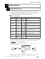
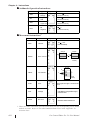
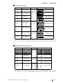
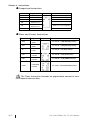
4.1
Instruction List .......................................................................................... 4–1
4.2
Instruction Details .................................................................................... 4–7
4.2.1
NO (Normally Open) .................................................................... 4–7
4.2.2
NC (Normally Closed) ................................................................. 4–9
4.2.3
OUT/M (Output Coil) .................................................................. 4–9
4.2.4
NEG (Negated Coil) ................................................................... 4–11
4.2.5
SET (Set Coil) ............................................................................. 4–11
4.2.6
RST (Reset Coil)......................................................................... 4–13
4.2.7
PT (Positive Transition Contact) ............................................... 4–13
4.2.8
NT (Negative Transition Contact) ............................................. 4–14
4.2.9
AND (And) .................................................................................. 4–15
4.2.10 OR (Or) ........................................................................................ 4–17
4.2.11 XOR (Exclusive OR) .................................................................. 4–17
4.2.12 NOT (Bit Invert) ......................................................................... 4–19
4.2.13 MOV (Transfer) .......................................................................... 4–19
Pro-Control Editor Ver. 5.0 User Manual
3
Preface
4.2.14 BMOV (Block Transfer) .............................................................. 4–20
4.2.15 FMOV (Fill Transfer) ................................................................... 4–22
4.2.16 SUM (Sum Total) ......................................................................... 4–24
4.2.17 AVE (Average) ............................................................................. 4–26
4.2.18 BCNT (Bit Count) ........................................................................ 4–28
4.2.19 ROL (Rotate Left) ........................................................................ 4–29
4.2.20 ROR (Rotate Right) ...................................................................... 4–30
4.2.21 SHL (Shift Left) ............................................................................ 4–31
4.2.22 SHR (Shift Right) .......................................................................... 4–33
4.2.23 RCL (Left Rotation with Carry) ................................................... 4–35
4.2.24 RCR (Right Rotation with Carry) ................................................. 4–36
4.2.25 SAL (Arithmetic Shift Left) .......................................................... 4–37
4.2.26 SAR (Arithmetic Shift Right) ........................................................ 4–38
4.2.27 ADD (Add) .................................................................................. 4–39
4.2.28 SUB (Subtract) ............................................................................. 4–40
4.2.29 MUL (Multiply) ............................................................................ 4–41
4.2.30 DIV (Divide) ................................................................................ 4–42
4.2.31 MOD (Modulus) .......................................................................... 4–43
4.2.32 INC (Increment) ........................................................................... 4–44
4.2.33 DEC (Decrement) ......................................................................... 4–44
4.2.34 SQRT (Square Root) .................................................................... 4–45
4.2.35 EQ (Compare: = ) ........................................................................ 4–46
4.2.36 GT (Compare: > ) ........................................................................ 4–47
4.2.37 LT (Compare: < ) ......................................................................... 4–47
4.2.38 GE (Compare: >= ) ...................................................................... 4–49
4.2.39 LE (Compare: <= ) ....................................................................... 4–49
4.2.40 NE (Compare: <> ) ...................................................................... 4–49
4.2.41 TON (Timer ON Delay) ............................................................... 4–51
4.2.42 TOF (Timer OFF Delay) .............................................................. 4–53
4.2.43 TP (Timer Pulse) ........................................................................... 4–55
4.2.44 CTU (UP Counter) ....................................................................... 4–57
4.2.45 CTD (DOWN Counter) ............................................................... 4–57
4.2.46 CTUD (UP/DOWN Counter) ...................................................... 4–59
4.2.47 BCD (BCD Conversion) .............................................................. 4–59
4.2.48 BIN (Binary Conversion) ............................................................. 4–60
4.2.49 ENCO (Encode) .......................................................................... 4–61
4
Pro-Control Editor Ver. 5.0 User Manual
Preface
4.2.50 DECO (Decode) .......................................................................... 4–62
4.2.51 RAD (Radian conversion) ............................................................ 4–62
4.2.52 DEG (Degree Conversion) ........................................................... 4–63
4.2.53 JMP (Jump) .................................................................................. 4–63
4.2.54 JSR (Jump Subroutine) ................................................................. 4–64
4.2.55 RET (Return Subroutine) .............................................................. 4–64
4.2.56 FOR/NEXT (Repeat) ................................................................... 4–65
4.2.57 PID (PID Calculation) .................................................................. 4–66
4.2.58 SIN (sine function) ....................................................................... 4–79
4.2.59 COS (cosine function) .................................................................. 4–79
4.2.60 TAN (tangent function) ................................................................. 4–80
4.2.61 ASIN (Arc Sine) .......................................................................... 4–80
4.2.62 ACOS (Arc Cosine) ..................................................................... 4–81
4.2.63 ATAN (Arc Tangent) .................................................................... 4–81
4.2.64 COT (Cotangent) ......................................................................... 4–82
4.2.65 EXP (Exponent) ........................................................................... 4–82
4.2.66 LN (Natural Logarithm) ............................................................... 4–83
CHAPTER 5
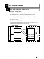
LS AREA REFRESH
5.1
LS Area Refresh Overview ...................................................................... 5–1
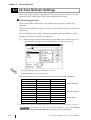
5.2
LS Area Refresh Settings ......................................................................... 5–2
5.2.1
5.3
LS Area - When not using a Device/PLC ...................................... 5–4
GLC and External Device Data Sharing ................................................. 5–7
5.3.1
CHAPTER 6
LS Area Refresh Cautions .............................................................. 5–9
GLC LADDER MONITOR FEATURE
6.1
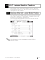
Overview of the GLC Ladder Monitor Feature ..................................... 6–1
6.2
Starting/Exiting the GLC Ladder Monitor ............................................. 6–3
6.3
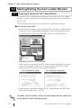
6.2.1
Preparing to operate the GLC Ladder Monitor .............................. 6–3
6.2.3
Exiting the GLC Ladder Monitor .................................................... 6–4
6.2.2
Starting the GLC Ladder Monitor .................................................. 6–5
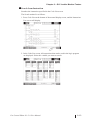
Various GLC Ladder Monitor Features ................................................. 6–5
6.3.1
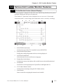
Online Monitor Feature (Normal Display) ...................................... 6–5
6.3.2
Rung Jump/Scroll Features ............................................................. 6–7
6.3.3
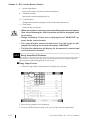
Instruction Enlarge Feature (Zoom Display) ................................... 6–7
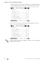
6.3.4
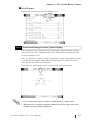
GLC Variable Monitor Feature ...................................................... 6–8
Pro-Control Editor Ver. 5.0 User Manual
5
Preface
6.3.5
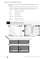
Setup Value Edit Feature ................................................................ 6–9
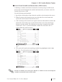
6.3.6
Variable/Instruction Search Feature .............................................. 6–11
CHAPTER 7
BACKUP
7.1
Overview of the Backup Feature ............................................................. 7–1
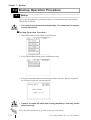
7.2
Backup Operation Procedure ................................................................... 7–2
7.2.1
Backup ........................................................................................... 7–2
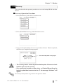
7.2.2
Recovery ........................................................................................ 7–3
CHAPTER 8
I/O DRIVERS
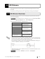
8.1
I/O Drivers Overview ................................................................................ 8–1
8.2
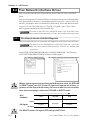
Flex Network Interface Driver ................................................................ 8–3
8.3
8.2.1
Flex Network Interface Unit Self-Diagnosis ................................... 8–3
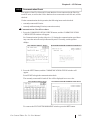
8.2.2
Communication Check ................................................................... 8–3
8.2.3
Error S-No. .................................................................................... 8–5
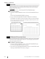
8.2.4
I/O Monitor (I/O Connection Check) ............................................ 8–5
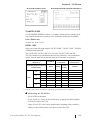
8.2.5
Flex Network Troubleshooting ..................................................... 8–11
DIO Driver ............................................................................................... 8–13
8.3.1
DIO Unit Self-Diagnosis ............................................................... 8–13
8.3.2
I/O Monitor (I/O Connection Check) .......................................... 8–15
8.3.3
DIO Troubleshooting .................................................................... 8–17
CHAPTER 9
ERROR MESSAGES
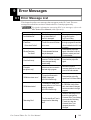
9.1
Error Message List ................................................................................... 9–1
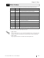
9.2
Error Codes ................................................................................................ 9–3
9.3
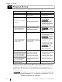
Program Errors ........................................................................................... 9–4
APPENDICES
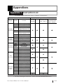
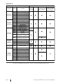
Appendix 1 Instruction List ................................................................................ A–1
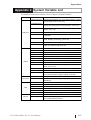
Appendix 2 System Variable List ....................................................................... A–3
INDEX
6
Pro-Control Editor Ver. 5.0 User Manual
Preface
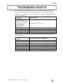
TRADEMARK RIGHTS
The company names and product names used in this manual are the trade names,
trademarks (including registered trademarks), and service marks of their respective
companies. This product does not include individual descriptions pertaining to the rights
held by each company.
Trademark /
Tradename
Rights Holder
Microsoft, MS, MS-DOS,
Windows, Windows 95,
Windows 98, Windows Me,
Windows NT, Windows
2000, Windows XP,
Windows Explorer,
Microsoft Excel
Microsoft Corporation, USA
Intel, Pentium
Intel Corporation, U.S.A.
Pro-face, Flex Network
Digital Electronics Corporation (worldwide)
Ethernet
Western Digital Electric Corporation, USA
Adobe, Acrobat
Adobe Systems Corporation
The following terms used in this manual differ from the official trade names and trademarks (listed above).
Term used in this
manual
Formal Tradename or Trademark
Windows 95
Microsoft® Windows® 95 Operating System
Windows 98
Microsoft® Windows® 98 Operating System
MS-DOS
Microsoft® MS-DOS® Operating System
Windows Me
Microsoft® Windows® Me Operating System
Windows NT
Microsoft® Windows NT® Operating System
Windows 2000
Microsoft® Windows® 2000 Operating System
Windows XP
Microsoft® Windows XP® Operating System
Pro-Control Editor Ver. 5.0 User Manual
7
Preface
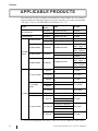
APPLICABLE PRODUCTS
The following is a list of products used with Pro-Control Editor Ver. 5.0 software.
In this manual, the following names are used to describe series units and products.
“GP Type” refers to GP-PRO/PB III for Windows Ver. 7.0.
Series
GLC100 Series
GLC300 Series
GLC2300 Series
Product
Name
Model
GP Type
GLC100L
GLC100-LG41-24V
GLC100L
GLC100S
GLC100-SC41-24V
GLC100S
GLC300T
GLC300-TC41-24V
GLC300T
GLC2300L
GLC2300-LG41-24V
GLC2300L
GLC2300T
GLC2300-TC41-24V
GLC2300
GLC2400 Series
GLC2400T
GLC2000
Series
GLC2500 Series
GLC2500T
GLC2600 Series
GLC2600T
GLC2400-TC41-24V
GLC2500-TC41-24V
GLC2500-TC41-200V
GLC2600-TC41-24V
GLC2600-TC41-200V
GLC150-BG41-XY32SK24V
GLC150-SC41-XY32SKLTC Type A1
24V
GLC150-BG41-XY32SCLT Type A2
24V
LT Type B
GLC150-BG41-FLEX-24V
LT Type A1
LT Type A Series
LT Type B/B+
Series
LT Series LT Type C Series
GLC150-BG41-XY32KF24V
GLC150-SC41-XY32KFLTC Type B+
24V
LT Type C
GLC150-BG41-RSFL-24V
LT Type B+
GLC2400 *1
“Rev.* - None, 1”
GLC2400*1
“Rev.* - Above2”
GLC2500
GLC2500
GLC2600*1
“Rev.* - None, 1”
GLC2600*1
“Rev.* - Above2”
GLC2600
LT TypeA
LTC TypeA
LT TypeA
LT TypeB/B+
LTC TypeB+
LT TypeC
GLC150-BG41-ADK-24V
LT Type H1
GLC150-BG41-ADPK-24V LT TypeH
GLC150-BG41-ADTK-24V
GLC150-SC41-ADK-24V
LT Type H Series
LTC Type H1 GLC150-SC41-ADPK-24V LTC TypeH
GLC150-SC41-ADTK-24V
GLC150-BG41-ADC-24V
LT Type H2
GLC150-BG41-ADPC-24V LT TypeH
GLC150-BG41-ADTC-24V
*1 For how to distinguish "Revisions", refer to "For GLC2400/GLC2600 Users".
8
Pro-Control Editor Ver. 5.0 User Manual
Preface
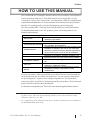
HOW TO USE THIS MANUAL
The GP-PRO/PB III C-Package03 manuals consist of seven volumes. A description of
each is found in the table below. These PDF manuals are located in disk 1 of your
C-Package03 CD set. (The “Setup Guide” is not included as a PDF file.) Supplemental
explanations and additional or revised information about functions may be provided as
data files. To read the data files, click the [Start] button, point to [Programs],
[Pro-face], and [ProPB3 C-Package], then click [ReadMe] to view this information.
For detailed information on Pro-face products, please refer to that product’s user
manual (sold separately).
GP-PRO/PB III C-Package03
Setup Guide
Describes software installation and basic application
development procedures.
Pro-Control Editor Ver. 5.0
Describes the software settings for combining with the
GLC, variables, and instructions.
Provides exercises for learning the basic functions, from
installation to operation, and a list of error messages.
Operation Manual
Describes procedures using the variables registered by
the Pro-Control Editor for use by the GP-PRO/PB III.
GP-PRO/PB III for Windows Ver. 7.0
Describes the installation, operating procedures, and
Operation Manual (PDF)
software functions of the GP screen creation software.
Explains "tags" for specifying on-screen functions of the
Tag Reference Manual
GP.
Describes the parts and symbols provided in the
Parts List
software for creating GP screens.
Describes procedures for connecting the GP to PLCs,
Device/PLC Connection
temperature controllers, and inverters of other
Manual
manufacturers.
User Manual (this manual)
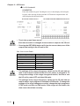
For your convenience, after you install the screen editor software, screen layout sheets
can be found in the Pro-face folder described below. You can use these layout sheets
for specifying the PLC registers when setting the tag addresses. The layout sheets
consist of two files: List of Device Assignments and Tag Layout Sheet. The location and
name of each file is shown in the following table.
For directions on using Microsoft® Excel, refer to the manuals supplied with the software.
* The abovementioned GP-PRO/PB III manuals describe the procedures for developing GP screens. The steps for developing GLC/LT screens are identical; simply
substitute “GLC/LT” for “GP.”
* As a supplement to the manuals listed above, detailed explanations are available in
the GP-PRO/PB III online help.
Pro-Control Editor Ver. 5.0 User Manual
9
Preface
Folder Name
Proface\propbwin\sheet
File Name
Contents
Device1E.xls
List of device assignments
TAG1E.xls
TAG2E.xls
TAG3E.xls
Tag layout sheet
TAG4E.xls
Adobe® Αcrobat® Reader is required to view the CD-ROM's PDF manuals.
PRODUCT USAGE PRECAUTIONS
WARNING
Do NOT use the GLC unit for control in situations where a
life-threatening accident or major machine damage could
occur.
Disk Media Usage Precautions
To prevent CD-ROM or floppy disk damage or data loss, be sure to observe the
followinginstructions:
• Be sure to remove the disk media from its disk drive prior to turning the PC
ON or OFF.
• Do NOT remove the disk media from its drive while the drive operation lamp is lit.
• Do NOT touch the disk media’s (CD-ROM or floppy disk) recording surface.
• Do NOT place the disk(s) where they may be exposed to extreme temperatures, high
humidity, or dust.
10
Pro-Control Editor Ver. 5.0 User Manual
Preface
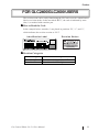
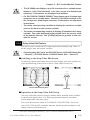
FOR GLC2400/GLC2600 USERS
The revision code can be easily found using the GLCunit’s rear face identification
label or revision sticker. In the area titled “REV”, the code is indicated by asterisks (*) or marked with a marker pen.
How to Read the Code
In the example below, asterisks (*) are placed at positions “D”, “1”, and “2”,
which indicates the revision version as “D-2”.
Identification Label
Revision Sticker
Revision Categories
Revision Types
“Rev.* - None, 1”
“Rev.* - Above2”
Meaning
The revision code is not used, or is “1”.
The revision code is "2" or higher.
Pro-Control Editor Ver. 5.0 User Manual
11
Preface
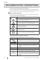
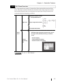
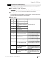
DOCUMENTATION CONVENTIONS
This manual uses the following symbols and terminology.
If you have any questions about the contents of this manual, please contact your local
Pro-face sales distributor. If you have any question about your personal computer or the
Windows® software, please contact your local distributor or manufacturer.
Safety Symbols and Terms
This manual uses the following symbols and terms for important information related to
the correct and safe operation of this product.
Symbol
Description
Incorrect operation resulting from negligence of this instruction
may cause death or serious injury.
Incorrect operation resulting from negligence of this instruction
may cause personal injury or damage to equipment.
Failure to observe this instruction may cause abnormal operation
of equipment or data loss.
Instructions / procedures that must be performed to ensure
correct product use.
Actions / procedures that should NOT be performed.
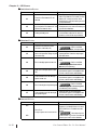
General Information Symbols and Terms
This manual uses the following symbols and terms for general information.
Symbol
Description
Provides hints on correct use or supplementary information.
Indicates related information (manual name, page number).
*1, *2, (etc.)
Pro-Control Editor
Controller
GP-PRO/PB III
GLC
External
Communication Device
12
Indicates related supplemental information.
Referred to in this manual as the "Editor." Software for editing,
transferring, and monitoring a GLC/LT unit’s ladder logic
program.
The control function of a GLC/LT unit.
Screen creation software GP-PRO/PBIII for Windows Ver. 7.0.
Indicates the “GLC/LT series” of graphic logic controllers
manufactured by the Digital Electronics Corporation.
Indicates peripheral devices including PLCs (programmable
logic controller), temperature controllers, and inverters. Note
that devices connected through Flex Network and DIO are not
included.
Pro-Control Editor Ver. 5.0 User Manual
1 Controller Features
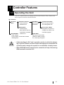
1.1 Operating the GLC
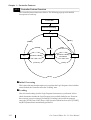
The GLC contains both screen display and I/O control features. These features and
their respective modes are described below.
GLC Features
Operation
Mode
Controller Features
RUN Mode
Constant Scan Mode
- Control Features
Logic Program
Runs the Logic Program
- Read/Write I/O
RUN Mode
at the designated time.
Percent Scan Mode
Display Mode
- Screen Display
Designates the percent of
- Data Transfer with PLC,
a single scan used by the
temperature controllers,
OFFLINE Mode
inverters, etc.
controller's program.
STOP Mode
- Initial Settings
Halt Logic Program Mode
- Logic Program, Screen Data Transfer
(Allows the editing, writing,
- Self Diagnosis
etc. of the Logic Program)
• Understanding the GLC unit’s operation modes is critical for designing a system. Please read this chapter thoroughly to understand the
operation and to design the system in consideration of safety issues.
• When OFFLINE mode is entered, the controller will stop. Re-entering
RUN mode will reset the GLC.
Pro-Control Editor Ver. 5.0 User Manual
1–1
Chapter 1 – Controller Features
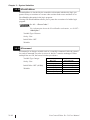
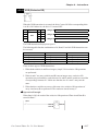
1.1.1
Controller Feature Overview
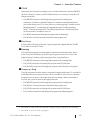
The Controller feature functions as follows. The following pages provide detailed
descriptions of each step.
P o w er ON
In itial P ro cessin g
L o ad in g
[RES ET]
[RES ET]
[P AUS E]
Te m po ra ry
S to p
[Pe rform 1 Scan]
[RES ET]
R[S
un
nPin] g
TO
[Co ntin ue ]
[RUN]
First S ca n
[Pe rform 1 Scan]
First Scan
S TO P
[S T O P ]
[S T O P ]
Initial Processing
This is the initial state that the engine uses to perform the Logic Program. Once initialization is finished, the Controller enters the “Loading” state.
Loading
Here, the actual reading-in of the Logic Program from memory is performed. After a
check determines whether the Logic Program is successfully loaded or not. If an error
has occurred, error processing is performed. If Loading is successful, the program
enters the [STOP] state. If the [Power ON] Operation Mode has been set to [START],
the [RUN] instruction is automatically performed.
1–2
Pro-Control Editor Ver. 5.0 User Manual
Chapter 1 – Controller Features
STOP
In this state, the Controller is waiting to receive another instruction. Once the [RESET],
[Perform 1 Scan], [Continue], or [PAUSE] instruction is received, the Controller will
change to that state.
• The [RESET] instruction will change the program to the [Loading] state.
At this time, variables are initialized. Retentive variables maintain data before the
power shuts down or the GLC resets. However, when triggering Controller reset in
Monitoring mode*1, or when using #Command, the value set in Programming
Mode*2 is used as the initial value. The [RUN] and [Perform 1 Scan] instructions
clear non-retentive variables to zero (0).
• The [RUN] instruction will change the program state to [Running].
• The [Perform 1 Scan] instruction will perform the program once.
First Scan
Executes the I/O Read, performs any Logic Program that is higher than the START
level, and executes the I/O write.
Running
This is the logic program execution engine’s continuous performance mode. In this
mode, it executes I/O Reads, performs Logic Programs, executes I/O writes, and
updates System Variables (such as #AvgLogicTime, #AvgScanTime).
• The [RESET] instruction will change the program to the [Loading] state.
• The [STOP] instruction will change the program to the [STOP] state.
• The [PAUSE] instruction will change the program to the [Temporary Stop] state.
Temporary Stop
The logic program execution engine is temporarily stopped in this state. To avoid an I/O
watchdog timeout, the system executes an I/O read and I/O write. However, the logic
program is not executed, so the output state does not change. When a command is
received, the system switches to the appropriate state.
• The [RESET] instruction will change the program to the [Loading] state.
• The [Perform 1 Scan] instruction will perform the program once.
• The [STOP] instruction will change the program to the [STOP] state.
• The [Continue] instruction will change the program to the [Running] state.
1. This mode is used to edit the program currently being executed by the controller.
2. This mode is used to create a program.
Pro-Control Editor Ver. 5.0 User Manual
1–3
Chapter 1 – Controller Features
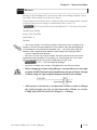
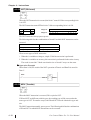
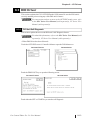
1.1.2
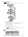
RUN Mode
RUN Mode uses the following steps.
Constant Scan /
Percent Scan
No
RUN Mode
Yes
Perform Logic
Program
END Processing
(Update System Variables, etc.)
No
64 Scan
Yes
Scan Time Adjustment
Scan
Completed
Scan Time Adjustment
This adjustment is performed every 64 scans. The various types of adjustments are
described below for Constant Scan Time and Percent Scan Time.
Constant Scan Time Mode
GLC scan time = (#AvgLogicTime x 100) / 50
Percent Scan Time Mode
GLC scan time = (#AvgLogicTime x 100) / #PercentAlloc
For information about #AvgLogicTime or #PercentAlloc, see Chapter 3 – “System Variables.”
The GLC or LT unit’s Scan Time includes an error.
Model
Difference
GLC100 Series
approx. - 0.2%
GLC300 Series
GLC2000 Series
approx. + 0.3%
LT Series
1–4
Pro-Control Editor Ver. 5.0 User Manual
Chapter 1 – Controller Features
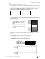
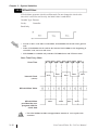
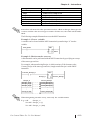
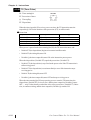
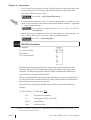
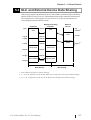
1.1.3
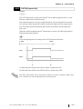
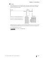
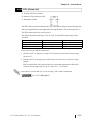
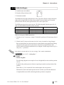
GLC Scan Overview
GLC Scan time has two modes: Constant Scan Time mode and Percent Scan Time
mode. Their basic scan time includes the Controller feature (logic program execution
time) and the Display feature (screen display/touch panel processing/external device
communication processing time), as follows.
Controller feature section
-I/O Input Data Read
1 START
Start
Stop
Operation
2
Logic time
Logic Program Execution
Operation
3
4 END
5 PEND
I/O Output Data Write
Display feature section
Scan
time
Executes only during the set scan time, minus
the logic time (when performing a constant
scan)
Graphic
processing
time
- Screen Display
- Touch Panel Processing
- Communication Processing
See 1.1.2 – “RUN Mode.”
Pro-Control Editor Ver. 5.0 User Manual
1–5
Chapter 1 – Controller Features
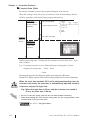
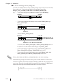
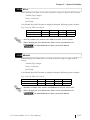
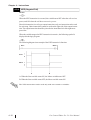
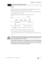
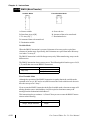
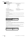
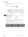
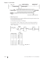
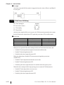
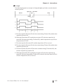
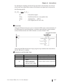
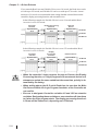
Constant Scan Mode
This mode constantly executes the program during the scan time set.
When this setting is used, the screen is used more often for data display and less
often for operation, with control (logic program) the priority.
Logic Time
Processing time
for logic program
(variable)
I/O Input Data Read
1 START
Start
Stop
Operation
2
Logic Program Execution
Operation
3
4 END
5 PEND
Scan time
(fixed scan
period)
I/O output Data Write
Graphic processing time
= Scan time logic time
Graphic processing time = Setting time for constant scan time mode (ms) – logic
time (variable)
E.g.: If constant scan time is set to 50ms and logic executing time is 20ms
Graphic processing time = 50ms – 20ms
= 30ms
The longer the logic time, the shorter the graphic processing time will become.
Though GLC display response will be slower, the logic program will execute continuously.
When the logic time exceeds 50 % of the designated setting value for
constant scan mode, the scan time is automatically adjusted so that it
is twice as long as the logic time.
E.g.: When the logic time is 30 ms and the constant scan mode is
50 ms, the scan time is 60 ms.
• Be sure to enter the setting value for the scan time in 10ms increments.
• When determining the value for the setting time, use the #AvgScanTime value
obtained from a test run of the GLC.
See 3.2.2 – “#AvgScanTime.”
1–6
Pro-Control Editor Ver. 5.0 User Manual
Chapter 1 – Controller Features
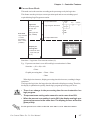
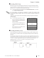
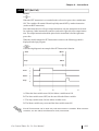
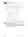
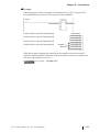
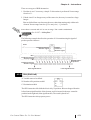
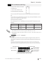
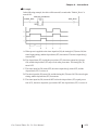
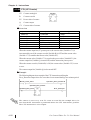
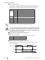
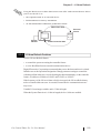
Percent Scan Mode
This mode varies the scan time according to the percentage set by the logic time
This feature sets the priority to screen operation speed and screen switching speed
required during Logic Program execution.
I/O Input Data Read
1 START
Start
Logic Time
Processing time
Logic Program Execution
Logic set time
+ screen
Operation
Operation
3
for logic program
Scan Time
Stop
2
4 END
5 PEND
(Set by percentage, variable)
I/O Output Data Write
processing
time = 100%
(variable)
Graphic processing time
= Total scan time
- Logic time (set
by %)
Scan time = Logic time / Percent scan set time (%)
E.g.: If percent scan time is set to 40% and logic execution time is 20ms
Scan time = (20 ÷ 40) x 100
= 50ms
Graphic processing time = 50ms – 20ms
= 30ms
When logic time increases, display processing time also increases, resulting in longer
scan times.
The longer the logic time, the longer the time allocated to display processing. Therefore,
the display is updated more quickly, but the logic program processing cycle slows.
• There is no change in the processing time for one instruction in a
logic program.
• The percent scan setting value cannot be set to more than 50%.
• When the percent scan setting is set to 50%, the display and logic program are processed at the same time. The display process will not be
given priority.
Set the percent scan value so that the scan time is set in 10ms increments.
Pro-Control Editor Ver. 5.0 User Manual
1–7
Memo
1–8
Pro-Control Editor Ver. 5.0 User Manual
2 Variables
This chapter explains the different types of variables used by Pro-Control Editor.
Using hardware-independent variables enhances the reusability of your programs.
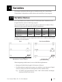
2.1 Variable Names
Pro-Control Editor uses variables to store I/O and counter data. Variables are userdesignated and are used as-is in the logic program.
In a conventional PLC, the area used to store data is called a device address. These
addresses are given specific names by each PLC manufacturer.
PLC Manufacturer
(Examples)
External I/O
Internal
Relay
Timer
Data
Register
Company "M"
X001
M100
T200
D00001
Company "O"
01
1001
TIM000
DM0000
Digital Electronics
Corporation
Switch1
Timerstart
Timer
Operating
Time
With Pro-Control Editor, you can assign names to these device addresses and use them
as variables in a logic program.
Pro-Control Editor
PLC
image
image
Manufacturer’s Device Address
Variable Name
(User-defined name)
When designating variable names, be aware of the following limitations.
• Maximum Variable Name length is 20 characters (20 bytes).
• No differentiation is made between upper-case and lower-case characters. If duplicates are created, only the first word registered will be enabled (valid).
E.g.: If “TANK” was registered before “tank,” “tank” will be invalid, even though
entering it will not create an error.
Pro-Control Editor Ver. 5.0 User Manual
2–1
Chapter 2 – Variables
• Except for the first character, variable names can use numbers.
• Variable names cannot contain spaces.
• The underscore ( _ ) is the only special character that can be used.
However, consecutive underscores ( __ ) cannot be used.
(OK: tank_1; Not OK: tank__1).
• The “#” sign cannot be used, since it is a reserved character, .
• “LS” and “LSS” are reserved variable names for use in the System Data Area, the
Read Area, and for Special Relays. Therefore, they cannot be used for user-defined
variable names.
See Chapter 5 – “LS Area Refresh.”
When creating variable names, Pro-face recommends using the underscore character to divide the variables into blocks, or groups. This will make the variable
names easier to find in the Pro-Control Editor’s variable list.
E.g.: If you have several conveyor belts in your factory system (Conveyer A,
Conveyor B, Conveyor C, etc.), include an identifying character in the motor
and sensor variable names:
Conveyor A variables:
A_Motor
A_Sensor
You could also name a Discrete (bit) as B, Integer as I, floating point as F:
AB_MotorStartingSwitch
AI_MotorRotationNumber
AF_MotorPowerRatio
Here, the variables used for contacts and coils are distinguished from the variables
used for basic mathematical operations.
• You can also use an array to set up variable names for each of your PLC’s
devices.
Example
PLC Device
Pro-Control Editor
Array Variable
Variable Type
External Input
X[100]
Discrete
External Output
Y[100]
Discrete
Internal Relay
M[100]
Discrete
Data Register
D[100]
Integer
For information about Variable Settings, refer to the Pro-Control
Editor Operation Manual, 2.4 – “Creating Variables.”
For information about reserved System Variables, see Chapter 3 –
“System Variables” Variable names can be designated by the user.
2–2
Pro-Control Editor Ver. 5.0 User Manual
Chapter 2 – Variables
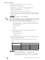
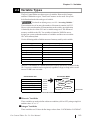
2.2 Variable Types
The Pro-Control Editor uses three types of variables: Discrete (bit), Integer,
and Real. Within these types, Timers and Counters are also used. Arrays can
be defined and used with each type of variable.
For details on defining arrays, see 2.3 – “Accessing Variables.”
The maximum size of an array (the number of elements it contains) is 65535.
However, the actual number of elements that can be used by any application
is limited by the size of the GLC unit’s variable storage area. The amount of
memory available to the GLC for variables is limited to 32KB. Be sure to
design your system so that the number of variables used does not exceed the
GLC unit’s memory limit.
Use the following table to find the amount of memory used by each variable.
Variable Type
Memory Used (unit:byte)
Discrete
12
Discrete Array
20 + (No. of elements x 12)
Integer
8
Integer Array
20 + (No. of elements x 8)
Real
16
Real Array
20 + (No. of elements x 16)
Timer
48
Counter
80
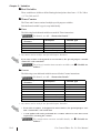
In the PLC, the number of variables that can be used by each device is limited. In the
GLC, however, variables can be registered, regardless of type, as long as the overall
limit of 32 KB is not exceeded.
Pro-Control Editor
Conventional PLC
External Input Contact (X)
Part A
External Output Contact (Y)
Part B
Internal Relay (M)
Part C
Data Register (D)
Part D
Timer
Part E
Counter
Part F
Variable
Real
Discrete
Integer
Counter
Timer
Total 32 KB
PLC Device and Pro-Control Variable Comparison
Discrete Variables
These variables are used to define a discrete condition, (ON or OFF), using a single bit
and the values “0” or “1.”
Integer Variables
These variables use 32 bits to define integer values from -2147483648 to 2147483647.
Pro-Control Editor Ver. 5.0 User Manual
2–3
Chapter 2 – Variables
Real Variables
These variables use 64 bits to define floating decimal point values from +/-2.25e-308 to
+/-1.79e+308, and “0”.
Timer/Counter
The Timer and Counter consist of multiple special-purpose variables.
Each dedicated variable’s type is set up individually.
Timer
The following four dedicated variables are used for Timer instructions.
For details, see 4.2 – “Instruction Details.”
Special-Purpose
Variables
Variable.PT
Description*1
Variable Type
Preset Value
Integer
Variable.ET
Current Value
Integer
Variable.Q
Timer Output Bit
Discrete
Variable.TI
Timer Measuring Bit
Discrete
1. Any names can be used for the Special-Purpose Variables.
Even when a timer is designated as non-retentive, the special-purpose variable
“Timer.PT” will retain data.
For a list of retentive/non-retentive variables, see “Variable Attributes.”
Counter
The following seven dedicated variables are used for the Counter instructions.
For details, see 4.2 – “Instructions Details.”
Special Purpose
Variables
Description*1
Variable Type
Variable.PV
Preset Value
Integer
Variable.CV
Current Value
Integer
Variable.R
Counter Reset
Discrete
Variable.UP
UP Counter
Discrete
Variable.QU
UP Counter Output
Discrete
Variable.QD
DOWN Counter Output
Discrete
Variable.Q
Counter Output
Discrete
1. Any names can be used for the Special-Purpose Variables.
• Even when a counter is designated as non-retentive, the special-purpose variable “Counter.PV” will retain data.
• A scan update will not be performed for a counter when it is reset. One scan is
required for resetting the counter.
For retentive/non-retentive variable details, see “Variable Attributes.”
2–4
Pro-Control Editor Ver. 5.0 User Manual
Chapter 2 – Variables
Variable Attributes
Variables have the following attributes, in addition to the variable type.
Internal
Used internally by the GLC. It cannot be used for external input/output. Internal variables are equivalent to PLC internal relays (internal registers).
Input/Output
External input/output is available. Assign variables to I/O in the [Configure I/O] window.
This feature is equivalent to the input/output relays of the PLC.
For I/O configuration details, refer to the Pro-Control Editor Operation Manual, 2.11 – “Assigning I/O.”
Retentive
Retentive-type variables use the GLC unit’s SRAM, which preserves data values in the
case of a power failure. The initial values for these variables are set via Programming
mode. When the GLC unit is powered down or reset, all current data is retained.
However, when the GLC unit’s Controller is reset in Monitoring mode or by using
#Command, or when logic programs are downloaded, all data is initialized using Programming mode preset values.
In addition, reading the GLC unit’s .PRW files will save the execution results to the
Editor. However, be careful when using retentive-type variables as initial values. If these
variables are designed to vary while the logic program is being executed, the predetermined initial values will be lost when the data is loaded into the Editor. Non-retentive
variables are either cleared to 0 or set to OFF.
After GP/GLC unit power is turned OFF and the backup battery runs
down, data stored in SRAM will be lost. When this happens, all SRAM
data is re-initialized to the value(s) set in Programming mode.
Global
These variables can be designated as either global or non-global. Specify "global" for
variables that are used to display Drawing Board Parts. Global variables are automatically registered as GLC symbols in the Symbol Editor when you save the ladder logic
program. These variables can also be shared with the Drawing Board’s display feature.
Global/non-global settings of multiple variables can be performed simultaneously by
selecting the desired variables from the Variable List. Up to 2048 global variables can
be set.
Refer to the Pro-Control Editor Operation Manual, 4.6 – “Changing
Variable Attributes.”
Preprogrammed system variables are set to “global” in the GLC unit’s initial settings.
Pro-Control Editor Ver. 5.0 User Manual
2–5
Chapter 2 – Variables
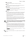
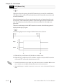
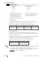
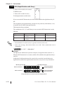
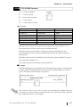
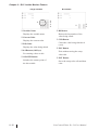
2.3 Accessing Variables
This section explains how to access variable array elements, bits, bytes and words with
Pro-Control Editor.
An array is a method of declaring and handling multiple elements with a single variable
name. Variables of the same type can be registered as one group using an array.
One analogy is the drawers of a cabinet.
The array variable Cabinet[10] has 10
drawers, numbered from [0] to [9]. These
drawers are called Cabinet[0], Cabinet[1],
. . . Cabinet[9]. Each drawer corresponds
to an individual data register in the PLC.
Cabinet
When using 10 locations of Cabinet
memory, first declare the variable name of
Cabinet and the array size (number of elements) of 10. The variable type settings
are listed as follows:
[0]
[1]
[2]
[3]
[4]
[5]
[6]
[7]
[8]
[9]
Accessing a Discrete Array
To access the elements of a Discrete array, a modifier [n] must be attached to each
element. To access the modifier, it is assigned an element number, but the first element
number in an array must be “0.”
E.g.: The Discrete array “MotorSetting” is a Discrete array of 10 elements. The
seventh element controls the output coil Fan. When the seventh element is turned
ON, the output coil turns ON. To access the seventh element of MotorSetting,
enter MotorSetting[6].
MotorSetting[6]
2–6
Fan
Pro-Control Editor Ver. 5.0 User Manual
Chapter 2 – Variables
Accessing an Integer/Integer Array
Integers and Integer Arrays can be accessed via array elements, bits, bytes, and words.
To access an array’s element, add [n] to the end of the variable name. To access using
bits, bytes, and words, the following suffixes are used. The modifier [m] is used to
denote the position of the element in the array being accessed.
Access Item/Unit
Suffix
Bit
.X[m]
Byte
.B[m]
Word
.W[m]
To Access an Element with the Integer Array
An Integer Array can be used for numerical calculation, tracking of repetitive information, and data logging.
E.g.: To record the number of sodas sold in
one month in the Integer Array
Water_Sales, design your array as
follows.
The array consists of 31 Integer type
elements that correspond to the 31 days
in a month.
[Day 1]
Water_Sales[0]
[Day 2]
Water_Sales[1]
[Day 3]
Water_Sales[2]
[Day 4]
Water_Sales[3]
—
—
—
[Day 28] Water_Sales[27]
[Day 29] Water_Sales[28]
[Day 30] Water_Sales[29]
[Day 31] Water_Sales[30]
The following diagram is an example of the Integer Array Pressure, using three elements.
• Pressure[0] represents the current pressure of the boiler.
• Pressure[1] represents the pressure upper limit value.
• Pressure[2] represents the pressure lower limit value.
When the pressure is higher or lower than the pressure limit, an alarm turns ON.
Current Pressure
Pressure Upper Limit Value
Pressure Lower Limit Value
Pressure[0]
Pressure[1]
Pressure[2]
High Pressure Alarm
Pressure[0]
Pressure[1]
Low Pressure Alarm
Pressure[0]
Pressure[2]
Pro-Control Editor Ver. 5.0 User Manual
2–7
Chapter 2 – Variables
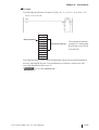
To Access an Integer Array using bits
As is the case with the discrete array variables, integer arrays can be accessed via bits,
bytes, and words. To access the m+1st bit of the n+1st element in the
Integer_Array_Variable_ Drink Sales, enter Drink_Sales[n].X[m].
E.g.: • To access the Integer array Alarm’s seventh bit, type Alarm.X[6].
32nd Bit
31
…
6
…
1
First Bit
0
7th Bit
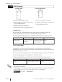
• To access the 62nd bit of the Integer array variable Water_Sales, type
Water_Sales.X[61].
32nd Bit
31
63 62
64th Bit
61
First Bit
1
0
33 32
33rd Bit
…
…
62nd Bit
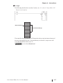
Also, for Water_Sales[1].X[29]:
32nd Bit
31
31 30
64th Bit
29
…
…
First Bit
1
0 First Ele m e nt (No. 0)
1
0 S e cond Ele m e n t (No.
33rd Bit
62nd Bit = F irst Ele m e nt's 29th Bit
As a result, since Water_Sales.X[61] = Water_Sales[1].X[29]‚ both can
be used to access the 62nd bit of the Integer array Water_Sales.
• To access the 6th byte of the Integer array variable Water_Sales‚ both
Water_Sales.B[5] and Water_Sales[1].B[1] can be used.
• To access the 5th word of the Integer array variable Water_Sales‚ both
Water_Sales.W[4] and Water_Sales[2].W[0] can be used.
Water_Sales.X[61] and Water_Sales[0].X[61] have the same meaning.
In the following example, the 3rd bit of the system variable #Status is used as a NO
instruction variable. The third bit of #Status identifies whether the GLC unit has an I/O
error or not. Therefore, when the third bit is turned ON, the output coil’s IO_Error is
turned ON, which provides notification that an I/O error has occurred.
2–8
Pro-Control Editor Ver. 5.0 User Manual
Chapter 2 – Variables
Accessing a Real Array
Real Arrays can be accessed using array elements. To access the elements of a Real
array, the modifier (n) must be attached to each element, which represents the element
number. Also, “0” is used for the first element in the array.
E.g.: To access the 5th element in the Real array SolutionTemperature, you would
use "SolutionTemperature[4]".
Pro-Control Editor can handle up to 2048 GLC variables. The elements of the
array become single variables. Thus, an array with five elements becomes five
variables.
A Real array can be used for numerical calculation, tracking of repetitive information
and data logging.
E.g.: To record the temperature of a solution every 24 hours in the Real array
Solution_Temperature, the structure of
data is as follows.
Solution_Temperature[0]
Solution_Temperature[1]
Solution_Temperature[2]
Solution_Temperature[3]
—
The array consists of 24 Real type elements that correspond to each hour of
a day.
—
—
Solution_Temperature[20]
Solution_Temperature[21]
Real element 0 corresponds to the
temperature data at 0:00.
Solution_Temperature[22]
Solution_Temperature[23]
Accessing an Indirect Array
Array elements[n] can be indirectly accessed by an Integer variable. Numbers in the
square brackets [ ] of suffixes such as .X[m], B[m], and W[m] can also be indirectly
accessed.
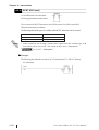
The following example assumes that you press the switch. In the INC instruction, "N"
increments by one with every single scan. The result of the ADD instruction (the sum of
"N" and "1"), is then assigned to A[N]. After five scans have been performed, "1" is
assigned to A[0], "2" to A[1], "3" to A[2], "4" to A[3], and "5" to A[4].
Note that the initial value of "N" is 0.
Switch
INC
ADD
N
N
Pro-Control Editor Ver. 5.0 User Manual
A[N]
1
2–9
Memo
2–10
Pro-Control Editor Ver. 5.0 User Manual
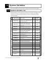
3 System Variables
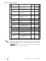
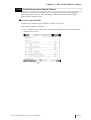
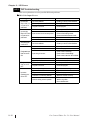
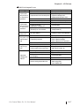
The following table provides a list of the Controller’s predefined System Variables.
3.1 System Variable List
Displays the average Logic Time
(Read, Perform, Write) once every
64 scans. (Unit: ms)
0
Integer
#AvgScanTime
Displays the latest Logic Time
(Read, Perform, Write, Display
processing) once every 64 scans.
(Unit: ms)
0
Integer
#LogicTime
Displays the latest Logic Scan Time
(Read, Perform, Write). (Unit: ms)
0
Integer
Excluding the current scan, counts
the number of scans performed.
Displays the latest Logic Scan Time
(Read, Perform, Write, Display
processing). (Unit: ms)
Displays the Watchdg Timer' value
set either in the editor or in offline
mode (Unit: ms)
Calculates the Percent Scan's
percentage. (Unit: % )
Sets the Constant Scan Time.
(Unit: ms)
Not currently used by GLC.
0
Integer
0
Integer
–
Integer
0
Integer
–
Integer
–
Integer
#ForceCount
Counts the number of times a
variable is forced ON or OFF.
0
Integer
#IOInfo
Not currently used by GLC.
Integer
#IOStatus
Displays the I/O Driver's condition.
#Platform
Indicates the controller's platform.
#Status
Indicates controller's current status.
#Version
Displays the controller's version data.
#FaultCode
Displays the latest error code
–
–
–
–
–
–
#FaultRung
Displays the rung where the error
occurred.
–
Integer
#IOFault
Turns ON when an error occurs.
–
Discrete
#Overflow
Turns ON when an overflow occurs
due to mathematical commands or
Real-to-Integer variable conversion.
0
Discrete
#AvgLogicTime
#ScanCount
#ScanTime
#WatchdogTime
#PercentAlloc
#TargetScan
Status
#ControlInfo
Pro-Control Editor Ver. 5.0 User Manual
Read Only
Variable
Name
Description
Write Only
Initial
Value
System Variable
Integer [10]
Integer
Integer
Integer
Integer
Read Only
ScanTime
Group
System Variables are used to display the Controller’s current state, and affect its operation. System variables are similar to variables and perform similarly. Since system
variables are preprogrammed and defined, they cannot be deleted and their names
cannot be changed.
3–1
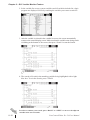
Variable
Name
#DisableAutoStart
Defines the mode entered when
the GLC starts up.
–
Discrete
#Fault
Used to stop the performance of
an Error Handler subroutine.
0
Discrete
#FaultOnMinor
Controls the completion of the
logic performed when a minor
error occurs.
0
Discrete
#Command
Changes the controller's mode.
0
Integer
#Screen
Switches GLC screens by
assigning screen numbers.
(BIN/BCD)
0
Integer
#Clock100ms
Create 0.1s clock.
Stores Year data as BCD tw o digits.
–
–
Discrete
#Year
#Month
Stores Month data as BCD two
digits.
–
Integer
#Day
Stores Day data as BCD tw o digits.
Stores Time data as BCD tw o digits.
–
–
Integer
#Time
#WeekDay
Stores Day data as an integer
value between 0 and 6
–
Integer
#EditCount
Not currently used by GLC.
Not currently used by GLC.
#WCLScan
Not currently used by GLC.
#WCLStatus
Not currently used by GLC.
–
–
–
–
Integer
#StopPending
#LadderMonitor
Starts and runs the GLC Ladder
Monitor Feature.
–
Integer
#PercentMemCheck
Not currently used by the GLC.
–
Integer
#RungNo
Sets the starting rung number to
be displayed by the GLC Ladder
Monitor Feature.
–
Integer
#StopScans
Not currently used by the GLC.
–
Integer
Write Only
Initial
Value
Write Only
Description
Integer
Discrete
Integer
Integer
Read Only
Integer
Read Only
System Variable
Write Only
Others
Time
Command
Status
Group
Chapter 3 – System Variables
#Year, #Month, #Day and #Time are saved as the GLC unit’s time data. Time data
changes are performed via the GLC unit’s Initial settings, or the System Data
Area’s Write settings.
Refer to the GLC Series User Manual (sold separately), GP-PRO/PB III
PLC/Device Connection Manual.
3–2
Pro-Control Editor Ver. 5.0 User Manual
Chapter 3 – System Variables
3.2 System Variable Details
This section describes each system variable in detail.
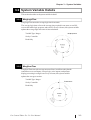
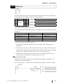
3.2.1
#AvgLogicTime
#AvgLogicTime stores the average logic time in ms units.
The average logic time refers to the average time required in one scan, to read I/O,
execute the ladder logic program, and read I/O. Every 64 scans, this system variable
updates the average logic time since its last calculation.
Variable Type: Integer
Set by: Controller
Read Only
ad
Re
D
Pr isp
oc
l
es ay
sin
g
3.2.2
Ex
ec
ut
e
e
rit
W
#AvgScanTime
#AvgScanTime stores the average amount of time, in milliseconds, that the
controller uses to read inputs, execute logic, write outputs, and perform
display processing in a single scan. Every 64 scans, this system variable
updates the average scan time.
Variable Type: Integer
Set by: Controller
Read Only
ad
Re
D
Pr isp
oc
l
es ay
sin
g
Pro-Control Editor Ver. 5.0 User Manual
Ex
ec
ut
e
e
rit
W
3–3
Chapter 3 – System Variables
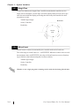
3.2.3
#LogicTime
#LogicTime indicates the length of time, in milliseconds, that the controller uses in a
single scan to read inputs, execute logic, and write outputs of the previous scan. Logic
time does not include the display processing time allowed by the controller for other
programs to execute.
Variable Type: Integer
Set by: Controller
3.2.4
ad
Re
ute
ec
Ex
Read Only
D
i
Pr spl
oc ay
es
sin
g
e
rit
W
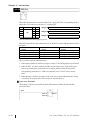
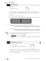
#ScanCount
#ScanCount is a counter incremented by the controller at the end of each scan.
The value range of #ScanCount is 0 – 16#FFFFFFFF. When the counter value exceeds
the maximum value (16#FFFFFFFF), the value of #ScanCount is set to zero (functioning as a Rollover, but without setting the Overflow variable).
Variable Type: Integer
Set by: Controller
Read Only
Whether or not a logic program is running can be easily checked using #ScanCount.
3–4
Pro-Control Editor Ver. 5.0 User Manual
Chapter 3 – System Variables
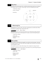
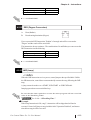
3.2.5
#ScanTime
#ScanTime stores the amount of time, in milliseconds, that the controller uses during its
last complete scan, to read I/O, execute logic, write I/O, and display processing.
Variable Type: Integer
Set by: Controller
Read Only
ad
Re
D
Pr isp
oc
l
es ay
sin
g
3.2.6
Ex
ec
ut
e
e
rit
W
#WatchdogTime
#WatchdogTime is used to set the value of the watchdog timer, in milliseconds. When
#ScanTime exceeds this value, a major fault occurs.
See 9.2 – “Error Codes.”
#WatchdogTime can be set in the initial settings or the configuration settings when the
controller is in RUN mode. #WatchdogTime is usually set up in the Setup dialog box.
Variable Type: Integer
Set by: User
Initial Value: 500ms
Writable
3.2.7
#PercentAlloc
#PercentAlloc is used when the controller is set to the Percent Scan mode. It sets the
percentage of the GLC unit’s total CPU time available to the controller. Set a scan time
value in multiples of 10ms.
#PercentAlloc can be set in the initial settings or the configuration settings when the
controller is in RUN mode. #PercentAlloc can usually be set up in the Setup dialog box.
See 1.1.2 – “RUN Mode.”
Variable Type: Integer
Set by: User
Range: 0 to 50%
Initial Value: 50
Writable
Pro-Control Editor Ver. 5.0 User Manual
3–5
Chapter 3 – System Variables
3.2.8
#TargetScan
#TargetScan is used when the controller is set to the Constant Scan mode.
The #TargetScan variable is designated in multiples of 10ms units.
When the logic time is constant, increasing the value in #TargetScan means that the
display processing time will be longer.
Decreasing the value in #TargetScan means that the display processing time will be
shorter. This is because most of the processing time is used by the controller.
#TargetScan can be set in the initial settings or the configuration settings when the
controller is in RUN mode. Typically, #TargetScan can be set up in the Setup dialog
box.
See 1.1.2 – “RUN Mode.”
Variable Type: Integer
Set by: User
Range: 10–2000ms
Initial Value: 10ms
Writable
3.2.9
#ForceCount
#ForceCount stores the number of variables that are forced ON or OFF in the current
ladder program.
Refer to the Pro-Control Editor Operation Manual, Section 3.2 –
“Starting and Stopping the Controller.”
Variable Type: Integer
Set by: Controller
Read Only
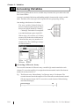
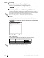
The Data Watch List window indicates the five variables that are forced ON or OFF in
the logic program.
3–6
Pro-Control Editor Ver. 5.0 User Manual
Chapter 3 – System Variables
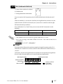
3.2.10 #IOStatus
#IOStatus is set by the I/O driver, and stores the I/O driver’s current status in
#IOStatus[1].
A value of 0 indicates that the I/O is normal. The status indicated by a value other
than 0 differs, depending on the I/O driver.
Variable Type: Integer[10]
Set by: Controller
Read Only
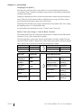
The Data Watch List window shows that Error 802 occurred in the I/O driver 1.
For I/O driver error code descriptions, see Chapter 8 – “I/O Drivers.”
3.2.11 #Platform
#Platform is used to store the platform number.
Variable Type: Integer
Set by: Controller
Initial Value: 1
Read Only
GLC Series
Value
16#04
16#14
16#84
16#44
16#4C
16#3C
16#94
16#9C
Platform
GLC100
GLC300
GLC2300
GLC2400 (Rev. *-None,1)*1
GLC2400 (Rev. *-Above2)*1
GLC2500
GLC2600 (Rev. *-None,1)*1
GLC2600 (Rev. *-Above2)*1
LT Series
Value
16#54
16#64
16#74
16#114
16#144
16#154
Platform
LT Type A
LT Type B/Type B+
LT Type C
LT Type H-AD
LT Type H-ADP
LT Type H-ADT
*1 For how to distinguish "Revisions", refer to "For GLC2400/GLC2600 Users".
Pro-Control Editor Ver. 5.0 User Manual
3–7
Chapter 3 – System Variables
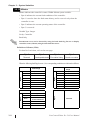
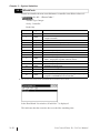
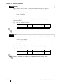
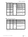
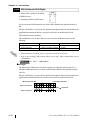
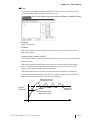
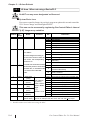
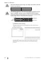
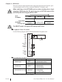
3.2.12 #Status
#Status indicates the controller’s status. Within #Status system variable:
• Byte 0 indicates the current fault conditions of the controller.
• Byte 1 is used to show the fault status history, and is reset to 0 only when the
controller is reset.
• Byte 2 indicates the current operating status of the controller.
• Byte 3 is reserved.
Variable Type: Integer
Set by: Controller
Read Only
Intermittent errors can be detected by using the latch fault flag. Be sure to display
controller status (#Status) using hexadecimal characters.
Definition of #Status (32bit)
For details of each item, refer to the next page.
Byte3
Reserved
Byte2
Byte1
Current operation status Error status history
Byte0
Current error status
When the following fault flags become 1, the corresponding conditions are indicated as follows:
Latched Fault
Flags
Bit0
Major fault
Bit1
Minor fault
Bit2
I/O fault
Bit3
Reserved
Bit4
Read error
Bit5
Bit6
Bit8
Bit9
Major fault
Minor fault
Bit10
I/O fault
Bit11
Reserved
Bit12
Read error
Reserved
Bit13
Reserved
Scan time error
Bit14
Scan time error
Bit7
Reserved
Bit15
Reserved
Bit16
Running
Bit17
I/O Enabled/Disabled
Bit18
Forces
Enabled/Disabled
Bit19
Paused
Bit20
Reserved
Bit 21-23
Reserved
Byte1
Byte0
Fault Flags
3–8
Byte3
Byte2
Controller Status
Reserved
Pro-Control Editor Ver. 5.0 User Manual
Chapter 3 – System Variables
Major fault, Minor fault :See 3.2.14 – “#FaultCodes.”
I/O fault
: See 3.2.16 – “#IOFault.”, See 3.2.10 – “#IOStatus.”
Read error
: The Editor’s program cannot be written to the Controller. This
can be due to any validity problem encoutered when the Controller evaluates the downloaded program. For example:
• Missing or wrong I/O driver.
• Corrupt program file.
Scan time error : Occurs if the average logic time, #AvgLogicTime, exceeds 50% of
#TargetScan.
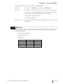
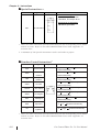
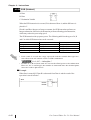
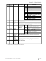
3.2.13 #Version
#Version indicates the version number of the controller. #Version is displayed in
hexadecimal format.
Variable Type: Integer
Set by: Controller
Read Only
Byte No.
Description
Ver. 1.0.0
Byte3
Major version
01
Byte2
Minor version
00
Byte1
Reserved
–
Byte0
Reserved
–
Pro-Control Editor Ver. 5.0 User Manual
3–9
Chapter 3 – System Variables
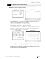
3.2.14 #FaultCode
#FaultCode identifies the most recent fault status. A controller resets all these values to 0.
See 8.2 – “Error Codes.”
Variable Type: Integer
Set by: Controller
Read Only
Code
Type
Cause
0
Normal
No fault.
1
Minor
Overflow resulting from a mathematical operation or a Real-toInteger conversion.
2
Major
Array reference is out of bounds.
3
Major
Bit reference of the Integer (32 bits) is out of bounds.
4
Major
Stack overflow.
5
Major
Invalid instruction code.
6
7
Reserved by the system
Major
8
9
Scan time exceeds watchdog time.
Reserved by the system
Major
10
Software error – typically a malfunctioning custom function
block – may require a system reboot to recover.
Reserved by the system
11
Reserved by the system
12
Minor
BCD/BIN conversion error
13
Minor
ENCD/DECO error*1
14
15
Reserved by the system
Minor
Backup memory's logic program (SRAM) is damaged. Logic
program in FEPROM will now be executed.*1
1. An error occurs only in the GLC2000 Series and LT Series units.
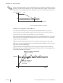
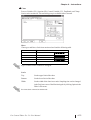
In the Data Watch List window, #FaultCode 7 is displayed.
This indicates that the scan time has exceeded the watchdog time.
3–10
Pro-Control Editor Ver. 5.0 User Manual
Chapter 3 – System Variables
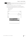
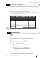
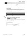
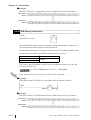
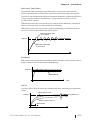
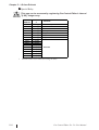
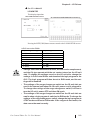
3.2.15 #FaultRung
#FaultRung stores the rung number where a fault occurred. #FaultRung is set to 0
if there are no faults.
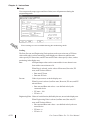
The following example shows when an error occurred at Rung 3.
This error is caused by subtracting the Integer by 0 when DIV Instruction is
executed. This error remains until the next error occurs or the controller is reset.
Variable Type: Integer
Set by: Controller
Read Only
Pro-Control Editor Ver. 5.0 User Manual
3–11
Chapter 3 – System Variables
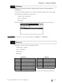
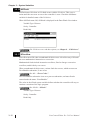
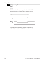
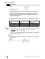
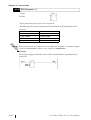
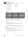
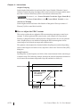
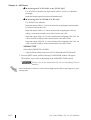
3.2.16 #IOFault
#IOFault turns ON when an I/O fault occurs with the I/O driver. This error remains until the next error occurs or the controller is reset. Check the #IOStatus
variable for detailed status of the I/O driver.
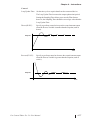
When #IOFault turns ON, #IOFault is displayed in the Data Watch List window.
Variable Type: Discrete
Set by: Controller
Read Only
For I/O driver error code descriptions, see Chapter 8 – “I/O Drivers.”
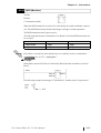
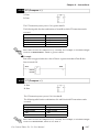
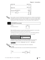
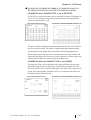
3.2.17 #Overflow
#Overflow turns ON when a mathematical fault occurs. #Overflow stays ON until
the next mathematical instruction or conversion.
Mathematical faults include instruction overflows, Real-to-Integer conversion
overflows, and divide by zero errors.
When a mathematical fault occurs, a minor fault also occurs, which executes an
ErrorHandler subroutine, if one exists.
See 9.2 – “Error Codes.”
The ErrorHandler subroutine is an error process subroutine, and must first be
created under the name “ErrorHandler.”
The value in the #Fault system variable defines whether the controller will stop or
continue execution of the logic program.
See 3.2.19 – “#Fault.”
Variable Type: Discrete
Set by: Controller
Read Only
3–12
Pro-Control Editor Ver. 5.0 User Manual
Chapter 3 – System Variables
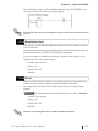
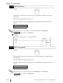
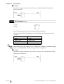
In the following example, the ErrorHandler subroutine detects BCD/BIN conversion errors and stops execution of the logic program.
If an overflow does not occur during Real-to-Integer conversion, #Overflow will not
turn ON.
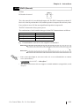
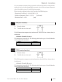
3.2.18 #DisableAutoStart
If the power is turned ON while #DisableAutoStart is ON, the controller starts up
in the STOP mode.
If the power is turned ON while #DisableAutoStart is OFF, the controller starts up
in the state that it was in (START or STOP) prior to shutdown.
The above settings are enabled only when the Controller State setting is set to
Default in the GLC unit’s initial settings.
Variable Type: Discrete
Set by: User
Initial Value: OFF
Writable
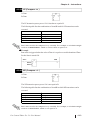
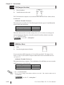
3.2.19 #Fault
#Fault is referred to by the controller as to whether the logic program will stop or
continue to execute at the completion of the ErrorHandler subroutine.
By turning #Fault ON, the controller will be able to stop executing the logic
program.
For information about ErrorHandler subroutines, see 3.2.17 – “#Overflow.”
Variable Type: Discrete
Set by: User
Initial Value: OFF
Writable
#Fault has no meaning when there is no ErrorHandler subroutine.
Pro-Control Editor Ver. 5.0 User Manual
3–13
Chapter 3 – System Variables
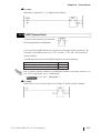
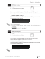
3.2.20 #FaultOnMinor
#FaultOnMinor is checked by the controller to determine whether the logic program will stop or continue to execute when a minor fault occurs and there is no
ErrorHandler subroutine in the logic program.
Turning ON #FaultOnMinor allows you to pause the execution of a ladder logic
program.
See 9.2 – “Error Codes.”
For information about the ErrorHandler subroutine, see 3.2.17 –
“#Overflow.”
Variable Type: Discrete
Set by: User
Initial Value: OFF
Writable
3.2.21 #Command
#Command is an Integer variable used as a controller command. After the controller reads #Command, its value is reset to 0, but bit 7 remains unchanged. When
multiple bits are ON, the lowest bit takes precedence.
Variable Type: Integer
Set by: User
3–14
Bit0 (=1)
Stop Controller
Bit1 (=2)
Run Controller
Bit2 (=4)
Reset Controller
Initial Value: OFF (all bits)
Bit3 (=8)
Execute single scan
Writable
Bit4 (=16)
Continue
Bit5 (=32)
Pause
Bit7 (=128)
Enable I/O
Pro-Control Editor Ver. 5.0 User Manual
Chapter 3 – System Variables
3.2.22 #Screen
#Screen is used to change GLC unit screens. This screen change variable’s operation differs from [Change Screen Check] as follows.
If the [Change Screen Check] feature is enabled and the screen change number is entered
in #Screen, after the screen change is completed the value is reset to “0”.
Pro-Control Editor Operation Manual Ch. 2 Creating a Program
Variable Type: Integer
Set by: User/Controller
Initial Value: 0
Writable
• The screen number set in #Screen defines which base screen to display. This
number is not the currently displayed screen number. The currently displayed
screen number is stored in the System Data Area — in LS[15] when using the
Memory Link Communication Method, and in LS[0] when using the Direct
Access Communication Method.
• #Screen is a write-only system variable. Therefore, DO NOT use #Screen in
applications that determine screen change, etc. To determine the screen number currently displayed, refer to the system data area (LS area).
see 5.2 - “LS Area Refresh Settings”
• #Screen is available only with the GLC2000 Series and LT Series units.
• When changing screens using #Screen, use the #Screen in the logic
program. Do NOT write directly to the #Screen using touch input. Change
screens using the logic program diagram below as an example.
• After power is turned ON, if the #Screen variable is used to change
the initial screen, be sure to wait more than 200ms or use the
LSS[0].x[3] (LS2032’s bit 3) bit rising (0 -> 1) timing.
Pro-Control Editor Ver. 5.0 User Manual
3–15
Chapter 3 – System Variables
3.2.23 #Clock100ms
#Clock100ms generates clock in milliseconds. Do not change the clock value
since this is used for read in only. An initial value is undefined.
Variable Type: Discrete
Set by:
Controller
Read Only
• If a GLC unit’s scan time exceeds 50ms, #Clock100ms clock will not be guaranteed.
• If the #Clock100ms clock reads in the internal clock 100ms at the beginning of
each GLC scan, an error will occur.
• #Clock100ms is available only with the GLC2000 Series and LT Series units.
Scan Time Every 30ms
Scan Time
Internal Clock
30ms 30ms 30ms
50ms
30ms 30ms 30ms
50ms
50ms
30ms
50ms
50ms
(100ms)
#Clock100ms Value
#Clock100ms
provides the user
program with the
clock data
60ms
60ms
30ms
60ms
• The #Clock100ms includes an approximate amount of error equal to the
scan time.
3–16
Pro-Control Editor Ver. 5.0 User Manual
Chapter 3 – System Variables
3.2.24 #Year
#Year displays Year data, as set in the controller, using two digits in BCD format.
Variable Type: Integer
Set by: Controller
Read Only
Year, Month, Day, and Time data are displayed using the following system variables.
E.g.: July 14, 2001 at 6:19 a.m.
Year
Month
Day
Time
System Variable
#Year
#Month
#Day
#Time
Value
1
7
14
619
• #Year is available only with the GLC2000 Series and LT Series units.
• When changing the Year, Month, Day, Time, use the System Data area.
GP-PRO/PBIII Device/PLC Connection Manual
3.2.25 #Month
#Month displays the Month data, as set in the controller, using two digits in BCD
format.
Variable Type: Integer
Set by: Controller
Read Only
Year, Month, Day, and Time data are displayed using the following system variables:
E.g.: July 14, 2001 at 6:19 a.m.
Year
Month
Day
Time
System Variable
#Year
#Month
#Day
#Time
Value
1
7
14
619
• #Month is available only with the GLC2000 Series and LT Series units.
• When changing the Year, Month, Day, Time, use the System Data area.
GP-PRO/PBIII Device/PLC Connection Manual
Pro-Control Editor Ver. 5.0 User Manual
3–17
Chapter 3 – System Variables
3.2.26 #Day
#Day displays the Day data, as set by the controller, using two digits in
BCD format.
Variable Type: Integer
Set by: Controller
Read Only
Year, Month, Day, and Time data are displayed using the following
system variables:
E.g.: July 14, 2001 at 6:19 a.m.
Year
Month
Day
Time
System Variable
#Year
#Month
#Day
#Time
Value
1
7
14
619
#Day is available only with the GLC2000 Series and LT Series units.
3.2.27 #Time
#Time displays Time data, as set in the controller, using four digits in BCD format.
Variable Type: Integer
Set by: Controller
Read Only
Year, Month, Day, and Time data are displayed using the following system variables.
E.g.: July 14, 2001 at 6:19 a.m.
Year
Month
Day
Time
System Variable
#Year
#Month
#Day
#Time
Value
1
7
14
619
#Time is available only with the GLC2000 Series and LT Series units.
3–18
Pro-Control Editor Ver. 5.0 User Manual
Chapter 3 – System Variables
3.2.28 #Weekday
#Weekday displays present Weekday data, with a value of 0 to 6.
Variable Type: Integer
Set by: Controller
Read Only
#Weekday reflects the number LS2054.
LS2054 cycles a value of 0 to 6 (.. 5J6J0J1J..) at the time-of-day change
(23:59 to 00:00).
When the power is plugged in, values of 0 to 6 are reflected by default. It is not necessarily reflect that Sunday is 0 and Monday is 1. To coordinate Weekday data with the
actual day of the week, use a keypad input display to enter values of 0 to 6 to LS2062.
#Weekday is available only with the GLC2000 Series and LT Series units.
Pro-Control Editor Ver. 5.0 User Manual
3–19
Chapter 3 – System Variables
3.2.29 #LadderMonitor
#LadderMonitor is used to start up and operate the GLC Ladder Monitor Feature.
Each operation is shown in the table below.
Variable Type: Integer
Set by: User
Writable
Bit Location
Items
0
1
2
3
4
Start/Exit bit
Scroll Left
Scroll Right
Scroll Up
Scroll Down
5
Screen/Rung changeover (0: Screen; 1: Rung)
6
Decimal/Hexadecimal change
7
Reserved
8
Search
9
Up
10
Down
11
Variable Search (0: Do NOT perform; 1: Perform)
12
Variable Selection (List Display)
13
Instruction Search (0: Do NOT perform; 1: Perform)
14
Instruction Selection (List Display)
15
Reserved
16
Controller (0: STOP; 1: RUN)
17
Clear Designated Search Item
18
Reserved
19
Reserved
20
Screen (0: Others; 1: GLC Ladder Monitor Normal Display)
21–30
31
Reserved
GLC Ladder Monitor is starting up.
#LadderMonitor is available only with the GLC2000 Series and LT Series units.
3–20
Pro-Control Editor Ver. 5.0 User Manual
Chapter 3 – System Variables
3.2.30 #RungNo
When the GLC Ladder Monitor is running, the starting rung number is stored in
#RungNo. If the GLC Ladder Monitor is not running, writing the rung number in
#RungNo, turns the GLC Ladder Monitor Starting Bit (#LadderMonitor’s bit 0)
from OFF to ON, the GLC Ladder Monitor starts up using the assigned rung
number as the starting rung.
Variable Type: Integer
Set by: User
Read Only (When GLC Ladder Monitor is started up.)
Writable (When GLC Ladder Monitor is not started.)
#RungNo is available only with the GLC2000 Series and LT Series units.
Pro-Control Editor Ver. 5.0 User Manual
3–21
Chapter 3 – System Variables
Memo
3–22
Pro-Control Editor Ver. 5.0 User Manual
Chapter 4 – Instructions
4 Instructions
4.1 Instruction List
The Instructions supported by the Pro-Control Editor software are as follows. This
chapter describes instructions used by the Pro-Control Editor. You cannot use some
instructions depending on the model and the revision. For details, refer to "For
GLC2400/GLC2600 Users" and "Appendix Instruction List".
Discrete Instructions
Instruction
Type
NO
Normally
Open
Allows power to pass when the contact
turns ON.
NC
Normally
Closed
Allows power to pass when the contact
turns OFF.
OUT/M*1
Output Coil /
Retention Coil
/
Turns physical output devices or internal
discrete variables and expressions ON or
OFF.
Negated Coil /
Negated
Retention Coil
/
Turns a variable OFF if the coil receives
power, and ON if it does not receive power.
SET/SM*1
Latch Coil /
Latch
Retention Coil
/
Turns a variable ON if the coil receives
power. Power remains ON until it receives
another explicit instruction.
RST/RM*1
Unlatch Coil /
Unlatch
Retention Coil
/
Turns a variable OFF if the coil receives
power. Power remains OFF until it receives
another explicit instruction.
PT*2
Positive
Transition
Allow s pow er to pass if the variable w as OFF
during the previous scan, but is currently ON.
NT*2
Negative
Transition
Allow s pow er to pass if the variable w as ON
during the previous scan, but is currently OFF.
NEG/NM
*1
Symbol
Function
1. For the instructions listed above, when a variable is retentive, it automatically
changes to one of the right-side instructions. Therefore, when inserting instructions
in this screen, be sure to use one of the left-side (non-retentive) instructions.
See 2.2 – “Variable Types.”
In the following example, when an OUT instruction’s variable is retentive, the
screen icon changes to M.
Designate
a variable
Variable is
converted to M
Select
“Retentive”
2. There is a limit to the maximum number of PT/NT instructions. See “Pro Control
Editor Operation Manual - Ch.3 Running the Ladder Logic Program”
Pro-Control Editor Ver. 5.0 User Manual
4–1
Chapter 4 – Instructions
Arithmetic Operation Instructions
Instruction
Type
Symbol
Function
AND
Logical
Multiply
A and B
C
Normal Continuity
OR
Logical
Add
A or B
C
Normal Continuity
XOR
Exclusive
Logical Add
A xor B
C
Normal Continuity
NOT
Bit
Negation
A C
Normal Continuity
Movement Instructions*1
Instruction
Type
MOV
Transfer
Symbol
Function
IN
OUT
Normal Continuity
Array A
Array E
B
BMOV
C
D
Block Transfer
Normal
Continuity
Array D
B
FMOV
File Transfer
A
C
Normal
Continuity
Sums up B through C, and stores
it to D.
SUM
Sum
AVE
Average
Calculates the average of B through C,
and stores it to D.
BCNT
Bit count
Stores the ON bit count of A to B.
1. There are some restrictions on instructions that you can use depending on the model
and the revision. Refer to "For GLC2400/GLC2600 Users" and "Appendix Instruction List".
4–2
Pro-Control Editor Ver. 5.0 User Manual
Chapter 4 – Instructions
Shift Instructions*1
Instruction
Type
Symbol
Function
ROL
Rotate Left
A
N Shift
C Normal Continuity
ROR
Rotate Right
A
N Shift
C Normal Continuity
SHL
Shift Left
SHR
Shift Right
A
N Shift
0
0
A
N Shift
C Normal Continuity
A
RCL
Left rotation with
carry
N Shift
RCR
Right rotation with
carry
N Shift
SAL
Arithmetic shift left
SAR
Arithmetic shift
right
C Normal Continuity
D Normal Continuity
A
D Normal Continuity
A
N Shift
0
A
N Shift
C Normal Continuity
C Normal Continuity
1. There are some restrictions on instructions that you can use depending on the model and
the revision. Refer to "For GLC2400/GLC2600 Users" and "Appendix Instruction List".
Mathematical Instructions*1
Instruction
Type
ADD
SUB
MUL
DIV
Add
Subtract
Multiply
Divide
MOD
Symbol
Function
A +B
C
Normal Continuity
A–B
C
Normal Continuity
AxB
C
Normal Continuity
A÷B
C
Normal Continuity
Residual
Processing
A%B
C
Normal Continuity
INC
Increment
A +1
A
Normal Continuity
DEC
Decrement
A–1
A
Normal Continuity
SQRT
Square root
A
B
Normal Continuity
1. There are some restrictions on instructions that you can use depending on the model and
the revision. Refer to "For GLC2400/GLC2600 Users" and "Appendix Instruction List".
Pro-Control Editor Ver. 5.0 User Manual
4–3
Chapter 4 – Instructions
Comparison Instructions
Instruction
EQ
GT
LT
GE
LE
NE
Type
Symbol
Function
Equal To (=)
When A = B, Continuity
Greater Than (>)
Less Than (<)
Greater Than or
Equal To (>=)
Less Than or
Equal To (<=)
Not Equal (< >)
When A > B, Continuity
When A < B, Continuity
When A > or = B, Continuity
When A < or = B, Continuity
When A < > B, Continuity
Timer and Counter Instructions
Instruction
Type
Symbol
Function
TON
ON Delay
Timer
See 4.2.41 – "TON (ON Delay Timer)."
TOF
OFF Delay
Timer
See 4.2.42 – "TOF (OFF Delay Timer)."
TP
Timer
Pulse
See 4.2.43 – "TP (Timer Pulse)."
CTU
UP
Counter
See 4.2.44 – "CTU (UP Counter)."
CTD
DOWN
Counter
See 4.2.45 – "CTD (DOWN Counter)."
CTUD
UP/DOWN
Counter
See 4.2.46 – "CTUD (UP/DOWN Counter)."
The Timer Instruction includes an approximate amount of error
equal to the scan time.
4–4
Pro-Control Editor Ver. 5.0 User Manual
Chapter 4 – Instructions
Convert Instructions*1
Instruction
Type
Symbol
Function
BCD
BCD
Conversion
A
BCD conversion
Normal Continuity
BIN
Binary
Conversion
A
Binary conversion
Normal Continuity
ENCO
Encode
A
Encode conversion
Normal Continuity
B
DECO
Decode
A
Decode conversion
Normal Continuity
B
RAD
Radian
conversion
(Degrees
Radians)
A
Radian conversion
Normal Continuity
B
DEG
Degree
conversion
(Radian
Degree)
A
Degree conversion
Normal Continuity
B
B
B
1. There are some restrictions on instructions that you can use depending on the model
and the revision. Refer to "For GLC2400/GLC2600 Users" and "Appendix Instruction List".
Program Control Instructions*1
Instruction
Type
Symbol
Function
JMP
Jump
->>label name
Jumps to a label
JSR
Jump to
Subroutine
->>Subroutine
Name<<-
Jumps to subroutine
RET
Return from
Subroutine
-<RETURN>-
Returns to called JSR command.
FOR, NEXT
Repeat
Repeats execution of the logic program
between FOR and NEXT for the number
of times assigned at A.
1. There are some restrictions on instructions that you can use depending on the model
and the revision. Refer to "For GLC2400/GLC2600 Users" and "Appendix Instruction List".
Pro-Control Editor Ver. 5.0 User Manual
4–5
Chapter 4 – Instructions
Special Instructions*1*2
Instruction
Type
Symbol
Function
When EN is energized:
SP and PV perform the PID
calculation, and output via CV.
When EN is not energized:
TB and CV go to MOV.
PID
PID Calculation
1. There are some restrictions on instructions that you can use depending on the model
and the revision. Refer to "For GLC2400/GLC2600 Users" and "Appendix Instruction List".
2. A maximum of 100 special instructions can be used within a project.
Function Control Instructions*1
Instruction
Type
SIN
sine function
COS
TAN
Function
A (Radians)
sin(A)
A(Radians)
function
Normal Continuity
tangent
A(Radians)
function
Normal Continuity
Arc sine
ACOS
Arc cosine
ATAN
Arc tangent
COT
Cotangent
EXP
Exponent
Natural
logarithm
B
Normal Continuity
cosine
ASIN
LN
Symbol
A
cos(A)
tan(A)
sin-1 (A)
B
B
B[Radian]
Normal Continuity
A
cos-1 (A)
B[Radian]
Normal Continuity
A
tan-1 (A)
B[Radian]
Normal Continuity
A[Radian]
1/tan(A)
B
Normal Continuity
A
eA
A
logeA
B Normal Continuity
B Normal Continuity
1. There are some restrictions on instructions that you can use depending on the model
and the revision. Refer to "For GLC2400/GLC2600 Users" and "Appendix Instruction List".
4–6
Pro-Control Editor Ver. 5.0 User Manual
Chapter 4 – Instructions
4.2 Instruction Details
This section describes the detail of each instruction. It explains the variable type (integer, integer array and so on) and the operation example in the variable mode, which you
can assign to each instruction operand. When you develop the logic program in the
fixed variable mode, you should assign the appropriate operand type while comparing
the table below with the variable type in the variable mode.
For details of the fixed variable mode, refer to "Appendix Fixed Variable Mode" of
"Pro-Control Editor Operation Manual".
Devices in the Fixed Variable Mode
Symbol Mark
Device Name
Type
Kind
D
Data Register
Integer
Internal Variable
W
Word Register
Real
Internal Variable
M
Subsidiary Relay
Bit
Internal Variable
T
Timer
Timer
Internal Variable
C
Counter
Counter
Internal Variable
P
PID
Integer Array
Internal Variable
Bit
Input
Integer
Input
Bit
Output
Integer
Output
X
XW
Y
YW
Input
Output
You can use the LS and LSS areas. For details, refer to "Chapter 5 LS
Area Refresh".
4.2.1
NO (Normally Open)
Variable
The NO instruction allows power to pass when the variable is ON.
The following diagram is an example of the NO instruction’s function.
Start
Motor
Start
Motor
A: When the Start variable turns ON, the Motor variable turns ON.
B: When the Start variable turns OFF, the Motor variable turns OFF.
Pro-Control Editor Ver. 5.0 User Manual
4–7
Chapter 4 – Instructions
4.2.2
NC (Normally Closed)
Variable
The NC instruction allows power to pass when the variable is OFF.
The following diagram is an example of the NC instruction’s function.
Start
Motor
Start
Motor
A: When the Start variable turns ON, the Motor variable turns OFF.
B: When the Start variable turns OFF, the Motor variable turns ON.
4–8
Pro-Control Editor Ver. 5.0 User Manual
Chapter 4 – Instructions
4.2.3
OUT/M (Output Coil)
Variable
The OUT instruction is used to turn ON/OFF the variables mapped to the I/O, or the
Discrete variables in the internal memory .
Since this instruction is a coil-type output instruction, only one instruction can be used
for each rung. Other instructions cannot be used on the right side of the output instruction. The output instruction should be placed to the immediate left of the right-most
power line.
When the variable mapped to the OUT instruction is retentive, the following symbol is
displayed in the logic program.
The following diagram is an example of the OUT instruction’s function .
Start
Motor
Start
Motor
A: When the Start variable turns ON, the Motor variable turns ON.
B: When the Start variable turns OFF, the Motor variable turns OFF.
The OUT instruction can be used only with non-retentive variables. With retentive variables, use the M (Retention Coil) instruction.
Pro-Control Editor Ver. 5.0 User Manual
4–9
Chapter 4 – Instructions
4.2.4
NEG (Negated Coil)
Variable
When the NEG instruction is executed, the variable turns OFF when the coil receives
power, and ON when the coil does not receive power.
Since this instruction is a coil-type output instruction, only one instruction can be used
for each rung. Other instructions cannot be used on the right side of the output instruction. The output instruction should be placed to the immediate left of the right-most
power line.
When the variable mapped to NEG instruction is retentive, the following symbol is
displayed in the logic program.
The following diagram is an example of the NEG instruction’s function.
Start
Motor
Start
Motor
A: When the Start variable turns ON, the Motor variable turns OFF.
B: When the Start variable turns OFF, the Motor variable turns ON.
The NEG instruction can be used only with non-retentive variables.
4–10
Pro-Control Editor Ver. 5.0 User Manual
Chapter 4 – Instructions
4.2.5
SET (Set Coil)
Variable
When the SET instruction is executed after the coil receives power, the variable turns
ON. The variable will remain ON until explicitly turned OFF by another instruction
(such as an RST instruction).
Since this instruction is a coil-type output instruction, only one instruction can be used
for each rung. Other instructions cannot be used on the right side of the output instruction. The output instruction should be placed to the immediate left of the right-most
power line.
When the variable mapped to SET instruction is retentive, the following symbol is
displayed in the logic program.
The following diagram is an example of the SET instruction’s function.
Start
Stop
Motor
Motor
Start
Motor
Stop
A: When the Start variable turns ON, the Motor variable turns ON.
B: The Start variable turns OFF, but does not affect the Motor variable.
C: The Stop variable turns ON, the Motor variable resets.
D: The Motor variable stays reset until the Start variable turns ON.
The SET instruction can be used only with non-retentive variables. With retentive
variables, use the SM (Latch Retention Coil) instruction.
Pro-Control Editor Ver. 5.0 User Manual
4–11
Chapter 4 – Instructions
4.2.6
RST (Reset Coil)
Variable
When the coil receives power after the RST instruction is executed, the variable turns
OFF. The variable remains OFF until explicitly turned ON by another instruction (such
as a SET instruction).
Since this instruction is a coil-type output instruction, only one instruction can be used
for each rung. Other instructions cannot be used on the right side of the output instruction. The output instruction should be placed to the immediate left of the right-most
power line.
When the variable mapped to the RST instruction is retentive, the following symbol is
displayed in the logic program.
The following diagram is an example of the RST instruction’s function.
Stop
Motor
Stop
Motor
A: When the Stop variable turns ON, the Motor variable resets.
B: When the Stop variable turns OFF, the Motor variable reset by the RST instruction
will remain OFF until another instruction turns it ON.
• The RST instruction can be used only with non-retentive variables. With retentive variables, use the RM (Unlatch Retention Coil) instruction.
• Real and Integer variables cannot be reset (set to zero) with an RST instruction.
4–12
Pro-Control Editor Ver. 5.0 User Manual
Chapter 4 – Instructions
4.2.7
PT (Positive Transition Contact)
Variable
When the PT instruction is executed, if the variable was OFF during the previous scan
but is currently ON, power is allowed to pass for a single scan.
When starting up the program, the state of positive transition contact during the previous
scan is considered to have been OFF.
The following diagram is an example of the PT instruction’s function.
Start
Motor
Previous
Scan
Current
Scan
Next
Scan
Next
Scan
Start
Motor
PT Detected
A: When the Start variable turns ON, the Motor variable turns ON.
B: After one scan (the current scan), the Motor variable turns OFF.
C: Since the rising edge of the variable Start is not detected, the variable Motor remains
OFF.
Be careful when using PT (Rising-type contacts) and NT (Falling-type
contacts) instruction operands for indirect addressing of elements in arrays or bit designations via variables.
The condition of variables set via operands and used during previous
program execution and those variables set for operands are compared
and then executed. Therefore, when designated variable values differ,
the condition comparison object also differs.
Pro-Control Editor Ver. 5.0 User Manual
4–13
Chapter 4 – Instructions
4.2.8
NT (Negative Transition Contact)
Variable
When the NT instruction is executed, if the variable was ON during the previous scan
but is currently OFF, power is allowed to pass for a single scan.
During the first scan, the state of transition during the previous scan is considered to
have been OFF. Therefore, the NT instruction does not pass power during the first
scan.
The following diagram is an example of the NT instruction’s function.
Start
Motor
Previous
Scan
Current
Scan
Next
Scan
Next
Scan
Start
Motor
NT Detected
A: When the Start variable turns OFF, the Motor variable turns ON.
B: After one scan, the Motor variable turns OFF.
C: Since the falling edge of the variable Start is not detected, the variable Motor remains
OFF.
Be careful when using PT (Rising-type contacts) and NT (Falling-type
contacts) instruction operands for indirect addressing of elements in arrays or bit designations via variables.
The condition of variables set via operands used during previous program execution and those variables set for operands are compared and
then executed. Therefore, when designated variable values differ, the condition comparison object also differs.
4–14
Pro-Control Editor Ver. 5.0 User Manual
Chapter 4 – Instructions
4.2.9
AND (And)
When the AND instruction is executed, the bit in C turns ON if the corresponding bit in
both A and B is ON. Otherwise, the bit in C is turned OFF.
A
Operator
ON
ON
OFF
AND
OFF
B
C
ON
ON
OFF OFF
Integer A 0
1
1
0
...
1
1
0
0
Integer B 1
1
0
0
...
0
0
0
1
Integer C 0
1
0
0
...
0
0
0
0
ON OFF
OFF OFF
The AND instruction always passes power.
The following table lists the combinations of A, B and C that can be used with an AND
instruction.
A
B
C
Integer
Integer
Integer
Integer Array
Integer Array
Integer Array
Integer
Integer Constant
Integer
Integer Array
Integer Constant
Integer Array
There are three types of AND instructions:
1. When all the variables are not array variables, a simple 32-bit AND operation is
performed.
2. When A and C are array variables and B is not an integer array, AND operations are
performed for each element of A and B, and the results are stored the corresponding
elements of C. Make sure that the size of A and C arrays are the same.
3. When the three variables are arrays of the same size, AND operations of array A
and array B are performed. The results are stored in array C.
Operation Example
When Start is ON, the 3rd digit of the 4-digit BCD data of Data A is masked to "0",
and the result is stored in Data C.
E.g.: When Data A is "16#5678" (5678 in hexadecimal system), "16#5078" is stored
in Data C.
Start
Data A
Data A
Data C
Data C
Pro-Control Editor Ver. 5.0 User Manual
4–15
Chapter 4 – Instructions
4.2.10 OR (Or)
When the OR instruction is executed, the bit in C turns ON if the corresponding bit in A
and/or B is ON. Otherwise, the bit in C is turned OFF.
A
Operator
ON
ON
OFF
OR
OFF
B
C
ON
ON
OFF ON
ON
Integer A 0
1
1
0
...
1
1
0
0
Integer B 1
1
0
0
...
0
0
0
1
Integer C 1
1
1
0
...
1
1
0
1
ON
OFF OFF
The OR instruction always passes power.
The following table lists the combinations of A, B and C in which OR instructions can be
executed.
A
B
C
Integer
Integer
Integer
Integer Array
Integer Array
Integer Array
Integer
Integer Constant
Integer
Integer Array
Integer Constant
Integer Array
There are three types of OR instructions:
1. When both variables A and B are integers, simple 32-bit OR operation is performed.
2. When A and C are array variables and B is not an integer array, logical OR operations are performed for each element of A and B, and the results are stored the
corresponding elements of C. Make sure that the size of A and C arrays are the
same.
3. When the three variables are arrays of the same size, logical OR operations of array
A and array B are performed. The results are stored in array C.
Operation Example
When Start is ON, the result of the logical OR operation of Data A and Data B is
stored in Data C.
Start
Data A
Data B
4–16
Data C
Pro-Control Editor Ver. 5.0 User Manual
Chapter 4 – Instructions
4.2.11 XOR (Exclusive OR)
When the XOR instruction is executed, the bit in C turns ON if the corresponding bit in
A or B is ON. Otherwise, the bit in C is turned OFF.
A
Operator
ON
ON
OFF
B
C
Integer A 0
1
1
0
...
1
1
0
0
Integer B 1
1
0
0
...
0
0
0
1
Integer C 1
0
1
0
...
1
1
0
1
ON OFF
XOR
OFF
OFF ON
ON
ON
OFF OFF
The XOR instruction always passes power.
The following table lists the combinations of A, B and C in which XOR instructions can
be executed.
A
B
C
Integer
Integer
Integer
Integer Array
Integer Array
Integer Array
Integer
Integer Constant
Integer
Integer Array
Integer Constant
Integer Array
There are three types of XOR instructions:
1. When both variables A and B are integers, simple 32-bit exclusive OR operations
are performed.
2. When A and C are array variables and B is not an integer array, exclusive OR
operations are performed for each element of A and B, and the results are stored the
corresponding elements of C. Make sure that the size of A and C arrays are the
same.
3. When the three variables are arrays of the same size, exclusive OR operations of
array A and array B are performed. The results are stored in array C.
Operation Example
When Start is ON, the result of the exclusive OR operation of Data A and Data B is
stored in Data C.
Start
Data A
Data B
Pro-Control Editor Ver. 5.0 User Manual
Data C
4–17
Chapter 4 – Instructions
4.2.12 NOT (Bit Invert)
When the NOT instruction is executed, the bit in C turns ON if the corresponding bit in
A is OFF.
The NOT instruction turns OFF the bit in C if the corresponding bit in A is ON.
A
ON
OFF
Operator
NOT
C
OFF
ON
Integer A
0
1
1
0
...
1
1
0
0
Integer C
1
0
0
1
...
0
0
1
1
The NOT instruction always passes power.
The following table lists the combinations of A and C in which NOT instructions can be
executed.
A
C
Integer
Integer Array
Integer
Integer Array
There are two types of NOT instruction:
1. When the A variables are integers, simple 32-bit bit conversion is performed.
2. When the A variables are an array, bit conversion is performed for the entire A array.
The result is stored in C. Make sure that the size of A and C arrays are the same.
Operation Example
When Start is ON, the result of the NOT operation of Data A and Data B is stored in
Data C.
Start
Data A
Data C
4.2.13 MOV (Transfer)
When the MOV instruction is executed, IN is copied to OUT.
If IN and OUT are different variable types, the resulting type will be converted to the
same type as OUT. To transfer arrays, both IN and OUT must be identical in type and
size.
The MOV instruction normally passes power. The following table lists the combinations
of IN and OUT in which MOV instructions can be executed.
4–18
Pro-Control Editor Ver. 5.0 User Manual
Chapter 4 – Instructions
IN Type
OUT Type
Discrete Array
Integer
Integer Array
Integer Constant
Real
Real Array
Real Constant
Discrete array same size as IN
Variable or Array in Integer or Real
Integer array or variable that is the same size as IN
Variable or Array in Integer or Real
Variable or Array in Integer or Real
Integer array or variable that is the same size as IN
Variable or Array in Integer or Real
#Overflow will turn ON if the operation involves a Real-to-Integer data-type conversion, and the value is too large to transfer. In this case, the result will be undefined.
The following examples illustrate how to use the MOV instruction.
Example 1: Clear a variable
A variable can be cleared with the MOV instruction by transferring a “0” into the
variable.
Clear_Sales
Sales
Example 2: Block-transfer an array
A block transfer can be performed with the MOV instruction by specifying two arrays
of the same type and size.
For example, when transferring Recipe A, which consists of 100 elements, to the
Current_Recipe of the same type and size, simply transfer Recipe A with a MOV
instruction.
Transfer_Recipe_A
Recipe_A
Recipe_A
Recipe_A [0]
Recipe_A [1]
Recipe_A [2]
Current_Recipe
Current_Recipe [0]
Current_Recipe [1]
Current_Recipe [2]
Recipe_A [99]
Current_Recipe [99]
Current_Recipe
When designating an entire array, enter only the variable names.
E.g.: OK
: Recipe_A
Not OK : Recipe_A [*]
Not OK : Recipe_A [100]
Pro-Control Editor Ver. 5.0 User Manual
4–19
Chapter 4 – Instructions
4.2.14 BMOV (Block Transfer)
Variable Mode
Fixed Variable Mode
A: Source variable
A: Source device
B: Start from Array A[B]
B: Amount of data to be transferred
C: To Array E[C]
C: Destination device
D: Amount of data to be transferred
E: Destination variable
Variable Mode
When the BMOV instruction is executed, elements of one array can be copied into
elements of another array. Specifically, the D elements are copied from index B in array
A to index C in array E.
The BMOV instruction is valid for Integer arrays only. When transferring, arrays can be
different sizes.
The BMOV instruction always passes power. The following table lists the types of A, B,
C, D, and E that can execute BMOV instructions.
A and E
B, C, and D
Integer Array
Integer
Integer Constant
Fixed Variable Mode
Although the operation of the BMOV instruction is equal to that in the variable mode,
operands to be set (A, B, E and so on) differ because the fixed variable mode does not
have the concept of an "Array".
If you execute the BMOV instruction in the fixed variable mode, elements as many as B
starting from the source initial address A will be copied to elements as many as B
starting from the destination initial address C.
This instruction always continues. A, B and C that you can execute the BMOV instruction are as the following.
4–20
A and B
C
Integer, Integer Constant
Integer
Pro-Control Editor Ver. 5.0 User Manual
Chapter 4 – Instructions
Example
When copying, Source [3], [4], and [5] of the seven source integer array elements are
copied to Destination [2], [3], and [4] of the six destination array elements. This data
transfer is performed as follows.
Start
Source
Source
Destination
Source[0]
Destination[0]
Source[1]
Source[2]
Destination[1]
Destination[2]
Source[3]
Source[4]
Destination[3]
Destination[4]
Source[5]
Source[6]
Destination[5]
Source [3] is copied to Destination [2].
Source [4] is copied to Destination [3].
Source [5] is copied to Destination [4].
Destination
While the program is running, the controller checks whether references to array A and E
elements exist in the BMOV instruction. If an invalid array is referred to, a major error
occurs and #FaultCode is set to 2.
See 3.2.14 – “#FaultCode.”
Pro-Control Editor Ver. 5.0 User Manual
4–21
Chapter 4 – Instructions
4.2.15 FMOV (Fill Transfer)
Variable Mode
Fixed Variable Mode
A: Source data
A: Source device
B: Start from Array D[B]
B: Amount of data to be transferred
C: Amount of data to be transferred
C: Destination device
D: Variable name of destination array
Variable Mode
When the FMOV instruction is executed, the C elements, starting at index B of Integer
array D, are filled with value A.
The FMOV instruction is valid for Integer arrays only. The FMOV instruction always
passes power.
The following table lists the types of A, B, C and D in which FMOV instructions can be
executed.
A, B, and C
D
Integer
Integer Constant
Integer Array
Fixed Variable Mode
Although the operation of the FMOV instruction is equal to that in the variable mode,
operands to be set (A, B, D and so on) differ because the fixed variable mode does not
have the concept of an "Array".
If you execute the FMOV instruction in the fixed variable mode, A will be stored in
elements as many as B starting from the destination initial address C.
The following table lists the types of A, B, and C in which FMOV instructions can be
executed.
4–22
A and B
C
Integer, Integer Constant
Integer
Pro-Control Editor Ver. 5.0 User Manual
Chapter 4 – Instructions
Example
When copying, the values are transferred to Destination [3], [4], [5], and [6] of the
seven destination array elements. The transfer operates as follows.
Start
TransferValue
Destination
TransferValue is copied to Destination[3].
Destination
TransferValue is copied to Destination[4].
Destination[0]
Destination[1]
TransferValue is copied to Destination[5].
Destination[2]
Destination[3]
TransferValue is copied to Destination[6].
Transfer
Value
Destination[4]
Destination[5]
Destination[6]
While the program is running, the controller checks whether references to array D
elements exist in the FMOV instruction. If an invalid array is referred to, a major error
will occur and #FaultCode is set to 2.
See 3.2.14 – “#FaultCode.”
Pro-Control Editor Ver. 5.0 User Manual
4–23
Chapter 4 – Instructions
4.2.16 SUM (Sum Total)
Variable Mode
Fixed Variable Mode
A: Array to calculate the sum total
A: Device to calculate the sum total
B: Initial number of the array element
range to be calculated (offset)
B: Number of elements to be calculated
C: Storing destination device
C: Element count to be calculated
D: Variable name of the storing destination
Variable Mode
If you execute the SUM instruction, it stores the sum total of elements as many as C
starting from B in the array A[n] to D. This instruction always continues.
A, B, C and D that you can execute the SUM instruction are as the following.
Type of A
Type of B
Integer, or Integer
Integer Array
Constant
Type of C
Type of D
Integer, or Integer
Constant (excluding
Integer
zero or below)
Fixed Variable Mode
Although the operation of the SUM instruction is equal to that in the variable mode,
operands to be set (A, B, D and so on) differ because the fixed variable mode does not
have the concept of an "Array".
If you execute the SUM instruction in the fixed variable mode, the sum total of elements
as many as B starting from the initial address A will be stored in C.
A, B and C that you can execute the SUM instruction are as the following.
Type of A and C
Type of B
Integer
Integer, Integer Constant
• If the number of elements to be calculated is equal to 0 (zero), it means the sum
total of 0 (zero) elements and the result will be equal to 0 (zero).
• If the result is out of range, which can be expressed in the variable type, #Overflow will be set to ON. The result in this case is "Undefined".
See 3.2.17 – “#Overflow.”
4–24
Pro-Control Editor Ver. 5.0 User Manual
Chapter 4 – Instructions
Example
The following describes the case when "A[10]={0, 1, 2, 3, 4, 5, 6, 7, 8, 9}, B=2, C=5".
D=(2+3+4+5+6)=20
ArrayA[0]
ArrayA[1]
B(Initial Number)
ArrayA[2]
ArrayA[3]
ArrayA[4]
ArrayA[5]
C(Calculation Range)
ArrayA[6]
ArrayA[7]
The sum total of elements
as many as C starting from
B in the array set to A[10]
is stored in D.
ArrayA[n-1]
The controller checks whether the SUM instruction refers to any inexistent elements of
the array A during RUN or not. If an invalid array is referred to, a major error will
occur and #Faultcode will be set to "2".
See 3.2.14 “#FaultCode.”
Pro-Control Editor Ver. 5.0 User Manual
4–25
Chapter 4 – Instructions
4.2.17 AVE (Average)
Variable Mode
Fixed Variable Mode
A: Array to calculate the average
A: Device to calculate the average
B: Initial number of the array element range
to be calculated (offset)
B: Number of elements to be calculated
C: Storing destination device
C: Element count to be calculated
D: Variable name of the storing destination
Variable Mode
If you execute the AVE instruction, it stores the average of elements as many as C
starting from B in the array A[n] to D. This instruction always continues.
The following table lists the types of A, B, C and D in which AVE instructions can be executed.
A
B
C
Integer, or Integer
Integer Array
Constant
D
Integer, or Integer
Constant (excluding
Real
zero or below)
Fixed Variable Mode
Although the operation of the AVE instruction is equal to that in the variable mode,
operands to be set (A, B, D and so on) differ because the fixed variable mode does not
have the concept of an "Array".
If you execute the AVE instruction in the fixed variable mode, the average of elements as
many as B starting from the initial address A will be stored in C.
The following table lists the types of A, B, and C in which AVE instructions can be executed.
A
B
C
Integer
Integer, Integer Constant
Real
• Decimals are omitted.
• If the result is out of range, which can be expressed in the variable type, #Overflow will be set to ON. The result in this case is "Undefined".
See 3.2.17 – “#Overflow.”
4–26
Pro-Control Editor Ver. 5.0 User Manual
Chapter 4 – Instructions
Example
The following describes the case when "A[10]={0, 1, 2, 3, 4, 5, 6, 7, 8, 9}, B=2, C=5".
D=(2+3+4+5+6)/5=4
ArrayA[0]
ArrayA[1]
B(Initial Number)
ArrayA[2]
ArrayA[3]
ArrayA[4]
ArrayA[5]
C(Calculation Range)
ArrayA[6]
ArrayA[7]
ArrayA[n-1]
The controller checks whether the AVE instruction refers to any inexistent elements of
the array A during RUN or not. If an invalid array is referred to, a major error will
occur and #Faultcode will be set to "2".
See 3.2.14 “#FaultCode.”
Pro-Control Editor Ver. 5.0 User Manual
4–27
Chapter 4 – Instructions
4.2.18 BCNT (Bit Count)
A: Variable name to be calculated
B: Storing destination variable name
If you execute the BCNT instruction, the ON bit count of A will be stored in B.
This instruction always continues.
The following table lists the types of A and B in which BCNT instructions can be executed.
A
B
Integer
Integer
Integer Constant
Integer
• If the result B is out of range, which can be expressed in the variable type of B,
#Overflow will be set to ON. The result in this case is "Undefined".
See 3.2.17 – “#Overflow.”
Example
The following describes the case when "A-38" (decimal) and "A=100110" (binary).
B=3 (decimal)
4–28
Pro-Control Editor Ver. 5.0 User Manual
Chapter 4 – Instructions
4.2.19 ROL (Rotate Left)
A: Variable name to be rotated
N: Number of bit positions to shift
C: Destination variable
The ROL instruction left-shifts the bits in A by N positions. Bits are rotated from the left
end (most significant bit) to the right end (least significant bit). The result is placed in C.
The ROL instruction always passes power.
The following table lists the types of A, N, and C in which ROL instructions can be
executed.
A
N
C
Integer
Integer Array
Integer Constant
Integer or Integer Constant
Integer or Integer Constant
Integer or Integer Constant
Integer
Integer Array is same size as A
Integer
There are two types of ROL instructions:
1. If both A and C are Integers, a simple 32-bit rotation is performed. N must range
from 0 to 31.
2. If both A and C are Integer arrays of the same size, the array is treated as a large
Integer.
Bits are shifted from one element to the next, rather than rotating only within each
element. N must range from 0 to [(32 x array size) – 1], inclusive.
#Overflow is turned ON if N is out of range. The result is undefined.
See 3.2.17 “#Overflow.”
Pro-Control Editor Ver. 5.0 User Manual
4–29
Chapter 4 – Instructions
Example
The following example describes the operation of a 1-bit rotation using a product
presence/absence signal.
Start
Product presence/
absence signal
Product
presence/
absence
signal
Bits
Product presence/
absence signal
Rotate Left 1 bit
position
Product presence/
absence signal
Most significant bit
Least significant bit
4.2.20 ROR (Rotate Right)
A: Variable name to be rotated
N: Number of bit positions to shift
C: Destination variable
The ROR instruction right-shifts the bits in A by N positions. Bits are rotated from the right
end (least significant bit) to the left end (most significant bit). The result is placed in C.
The ROR instruction always passes power.
The following table lists the types of A, N, and C in which ROR instructions can be
executed.
4–30
A
N
C
Integer
Integer Array
Integer Constant
Integer or Integer Constant
Integer or Integer Constant
Integer or Integer Constant
Integer
Integer Array is same size as A
Integer
Pro-Control Editor Ver. 5.0 User Manual
Chapter 4 – Instructions
There are two types of ROR instruction.
1. If neither A nor C is an array, a simple 32-bit rotation is performed. N must range
from 0 to 31.
2. If both A and C are Integer arrays of the same size, the array is treated as a large
Integer.
Bits are shifted from one element to the next, rather than rotating only within each
element. N must range from 0 to [(32 x array size) – 1], inclusive.
#Overflow is turned ON if N is out of range. The result is undefined.
See 3.2.17 – “#Overflow.”
Example
The following example describes the operation of 1-bit rotation using the signal of
product presence/absence.
Start
Product presence/
absence signal
Product
presence/
absence signal
Bits
Product presence/
absence signal
Product presence/
absence signal
Most significant bit
Rotated Right 1
bit position
Least significant bit
4.2.21 SHL (Shift Left)
A: Variable name to be shifted
N: Number of bit positions to shift
C: Destination variable
The SHL instruction left-shifts the bits in A by N positions. Bits are dropped from the
left end (most significant bit) of the element, and 0 is inserted in the now-vacant bit
positions at the right end (least significant bit). The result is placed in C.
The SHL instruction always passes power.
Pro-Control Editor Ver. 5.0 User Manual
4–31
Chapter 4 – Instructions
The following table lists the types of A, N and C in which SHL instructions can be
executed.
A
N
C
Integer
Integer Array
Integer Constant
Integer or Integer Constant
Integer or Integer Constant
Integer or Integer Constant
Integer
Integer Array is same size as A
Integer
There are two types of SHL instruction.
1. If neither A nor C is an array, a simple 32-bit shift is performed. N must range from 0
to 31.
2. If both A and C arrays are the same size, the A array is treated as a large Integer.
Bits are shifted from one element to the next, rather than the most significant bit being
dropped from the left end of each element. Only the most significant bit of the
highest-numbered element within the array is dropped. N must range from 0 to
[(32 x array size) – 1], inclusive.
#Overflow is turned ON if N is out of range. The result is undefined.
See 3.2.17 – “#Overflow.”
Example
The following diagram is an example of a one-bit left shift, used to track the position of a
bit.
Each bit in the product presence/absence signal represents the actual position of the
product.
When "Move_Cart" is turned ON, bit is shifted left to the next position.
When the bit reaches the final bit position in the variable (31), the Product Removal
Completion Bit is turned ON, indicating that the operation is completed.
Product presence/ x[31]
absence signal
Move_Cart
Product presence/
absence signal
Product Removal
Completion Bit
Product presence/
absence signal
Bits
Product presence/
absence signal
Shift Left 1 bit position
Delete
Product presence/
absence signal
Position after the operation
4–32
Pro-Control Editor Ver. 5.0 User Manual
Chapter 4 – Instructions
4.2.22 SHR (Shift Right)
A: Variable name to be shifted
N: Number of bit positions to shift
C: Destination variable
The SHR instruction right-shifts the bits in A by N positions. Bits are dropped from the
right end (least significant bit) of the element, and 0 is inserted in the now-vacant bit
positions at the left end (most significant bit). The result is placed in C.
The SHR instruction always passes power. The following table lists the types of A, N,
and C in which SHR instructions can be executed.
A
N
C
Integer
Integer Array
Integer Constant
Integer or Integer Constant
Integer or Integer Constant
Integer or Integer Constant
Integer
Integer Array is same size as A
Integer
There are two types of SHR instructions.
1. If neither A nor C is an array, a simple 32-bit shift is performed. N must range from 0
to 31.
2. If both A and C arrays are the same size, the A array is treated as a large Integer.
Bits are shifted from one element to the next, rather than the least significant bit being
dropped from the right end of each element. Only the least significant bit of the
lowest-numbered element within the array is dropped. N must range from 0 to [(32 x
array size) – 1], inclusive.
#Overflow is turned ON if N is out of range. The result is undefined.
See 3.2.17 – “#Overflow.”
Example
• When Using Bits
The following diagram is an example of a one-bit right shift, used to track the position
of a bit.
Each bit in the product presence/absence signal represents the actual position of the
product.
When "Move_Cart" is turned ON, bit is shifted right to the next position.
When the bit reaches the final bit position in the variable (0), the Product Removal
Completion Bit is turned ON, indicating that the operation is completed.
Pro-Control Editor Ver. 5.0 User Manual
4–33
Chapter 4 – Instructions
Product presence/
absence signal .x[0]
Move_Cart
Product Removal
Completion Bit
Product presence/
absence signal
Product presence/
absence signal
Bits
Product presence/
absence signal
Shifted Right
1 bit position
Delete
Product
presence/
absence
signal
The position after the operation
• When Using Arrays
The following diagram is an example an SHR instruction being used to transfer values
of each element in an Integer array.
A 32-bit shift rotates the entire 32-bit Integer.
Every second, the “Table1” Integer array’s values are moved up one position towards Element 0, and a new value becomes the last element “Table1[99]” in the
“Table1” Integer array.
Timer2
Timer2_Start
Table1
Table1
New_Value
Table1[99]
Delete
Element Table1
Table1
New_Value = 3
4–34
Pro-Control Editor Ver. 5.0 User Manual
Chapter 4 – Instructions
4.2.23 RCL (Left Rotation with Carry)
A: Name of the variable to be rotated
N: Shift bit count
C: Name of the variable for carry
D: Storing destination variable name
If you execute the RCL instruction, the A bit will be shifted to the left direction by N
bits.
The far left bit (most significant bit) is stored in a carry, and carry information (1 or 0) is
rotated to the far right bit (least significant bit).
This instruction always continues.
The combination of A, N, C and D that you can execute the RCL instruction is as the
following.
Type of A
Type of N
Type of C
Type of D
Integer
Integer, or Integer
Bit
Integer
Bit
Integer
Constant
Integer Constant
Integer, or Integer
Constant
• You should set N to be 0 (zero) or greater and to be 32 or less.
• If N is out of range, #Overflow will be set to ON. The result in this case is
"Undefined".
See 3.2.17 – “#Overflow.”
Example
The figure below indicates the operation example of a single bit rotation (when N=1).
When the RCL instruction is executed, each bit will be shifted to the left direction by 1
(one) bit.
At this time, bit information stored in a carry before execution is stored in the least
significant bit, and the most significant bit is stored in a carry as new carry information.
Most Significant Bit
Least Significant Bit
Before execution
Carry Information
before execution
After execution
Carry Information
after execution
The most significant bit is stored in a carry.
Pro-Control Editor Ver. 5.0 User Manual
4–35
Chapter 4 – Instructions
4.2.24 RCR (Right Rotation with Carry)
A: Name of the variable to be rotated
N: Shift bit count
C: Name of the variable for carry
D: Storing destination variable name
If you execute the RCR instruction, the A bit will be shifted to the right direction by N
bits.
The far right bit (most significant bit) is stored in a carry, and carry information (1 or 0)
is rotated to the far left bit (least significant bit).
This instruction always continues.
The combination of A, N, C and D that you can execute the RCR instruction is as the
following.
Type of A
Type of N
Type of C
Type of D
Integer
Integer, or Integer
Bit
Integer
Bit
Integer
Constant
Integer Constant
Integer, or Integer
Constant
• You should set N to be 0 (zero) or greater and to be 32 or less.
• If N is out of range, #Overflow will be set to ON. The result in this case is
"Undefined".
See 3.2.17 – “#Overflow.”
Example
The figure below indicates the operation example of a single bit rotation (when N=1).
When the RCR instruction is executed, each bit will be shifted to the right direction by 1
(one) bit.
At this time, bit information stored in a carry before execution is stored in the most
significant bit, and the least significant bit is stored in a carry as new carry information.
Most Significant Bit
Least Significant Bit
Before execution
Carry Information
before execution
After execution
Carry Information
after execution
Carry information is stored in the most significant bit.
4–36
Pro-Control Editor Ver. 5.0 User Manual
Chapter 4 – Instructions
4.2.25 SAL (Arithmetic Shift Left)
A: Name of the variable to be shifted
N: Shift bit count
C: Storing destination variable name
If you execute the SAL instruction, the A bit will be shifted to the left direction by N
bits.
When it is shifted by 1 (one) bit, the far left bit (most significant bit) remains as it is, the
2nd bit from the far left bit is lost and 0 (zero) is stored in a vacant bit on the far right.
This instruction always continues.
The combination of A, N and C that you can execute the SAL instruction is as the
following.
Type of A
Type of N
Type of C
Integer
Integer, or Integer Constant
Integer
Integer Constant
Integer, or Integer Constant
Integer
• You should set N to be 0 (zero) or greater and to be 31 or less.
• If N is out of range, #Overflow will be set to ON. The result in this case is
"Undefined".
See 3.2.17 – “#Overflow.”
Example
The figure below indicates the operation example of a single bit rotation (when N=1).
When the SAL instruction is executed, each bit will be shifted to the left direction by 1
(one) bit.
At this time, only the most significant bit is not shifted, it is stored in the most significant
bit as it is after execution and 0 (zero) is stored in the least significant bit.
Most Significant Bit
Least Significant Bit
Before execution
Removed
After execution
Pro-Control Editor Ver. 5.0 User Manual
0 (zero) is stored
in the least
significant bit
4–37
Chapter 4 – Instructions
4.2.26 SAR (Arithmetic Shift Right)
A: Name of the variable to be shifted
N: Shift bit count
C: Storing destination variable name
If you execute the SAR instruction, the A bit will be shifted to the right direction by N
bits.
When it is shifted by 1 (one) bit, the far right bit (least significant bit) is lost and the most
significant bit information before execution is stored in a vacant bit on the far left.
This instruction always continues.
The combination of A, N and C that you can execute the SAR instruction is as the
following.
Type of A
Type of N
Type of C
Integer
Integer, or Integer Constant
Integer
Integer Constant
Integer, or Integer Constant
Integer
• You should set N to be 0 (zero) or greater and to be 31 or less.
• If N is out of range, #Overflow will be set to ON. The result in this case is
"Undefined".
See 3.2.17 – “#Overflow.”
Example
The figure below indicates the operation example of a single bit rotation (when N=1).
When the SAR instruction is executed, each bit will be shifted to the right direction by 1
(one) bit.
When it is shifted by 1 (one) bit, the far right bit (least significant bit) is lost and the most
significant bit information before execution is stored in a vacant bit on the far left.
Most Significant Bit
Least Significant Bit
Before execution
Removed
After execution
4–38
Pro-Control Editor Ver. 5.0 User Manual
Chapter 4 – Instructions
4.2.27 ADD (Add)
A: Data
B: Data
C: Destination Variable
When the ADD instruction is executed, A and B are added, and the result is placed in C.
If both A and B are Integers or Integer constants, the ADD instruction performs an
Integer addition. Otherwise, the instruction performs a floating-point instruction, which
may reduce the processing speed.
The ADD instruction always passes power. The following table lists the combinations of
A, B and C in which ADD instructions can be executed.
A
B
C
Integer
Integer Constant
Real
Real Constant
Integer
Integer Constant
Real
Real Constant
Integer or Real
Integer or Real
Integer or Real
Integer or Real
• If the result C exceeds the range expressed with the variable data type in C,
#Overflow turns ON and the result of ADD is undefined.
See 3.2.17 – “#Overflow.”
• If either A or B are Real, both are converted to Real prior to the addition.
However, if C is an Integer, the number is truncated after the decimal point,
since the result is placed in C.
Example
When Start is turned ON, Data A and Data B are added and the result of the operation
is stored in Data C.
Start
Data A
Data B
Pro-Control Editor Ver. 5.0 User Manual
Data C
4–39
Chapter 4 – Instructions
4.2.28 SUB (Subtract)
A: Data
B: Data
C: Destination Variable
When the SUB instruction is executed, B is subtracted from A, and the difference is
placed in C.
If both A and B are Integers or Integer constants, the SUB instruction performs an
Integer subtraction. Otherwise, the instruction performs a floating-point instruction,
which may reduce the processing speed.
The SUB instruction always passes power. The following table lists the types of A, B
and C in which SUB instructions can be executed.
A
B
C
Integer
Integer Constant
Real
Real Constant
Integer
Integer Constant
Real
Real Constant
Integer or Real
Integer or Real
Integer or Real
Integer or Real
• If the result C exceeds the range expressed with the variable data type in C,
#Overflow turns ON and the result of SUB is undefined.
See 3.2.17 – “#Overflow.”
• If either A or B are Real, both are converted to Real prior to the subtraction.
However, if C is an Integer, the number is truncated after the decimal point,
since the result is placed in C.
Example
When Start is turned ON, Data B is subtracted from Data A and the result of the
operation is stored in Data C.
Start
Data A
Data B
4–40
Data C
Pro-Control Editor Ver. 5.0 User Manual
Chapter 4 – Instructions
4.2.29 MUL (Multiply)
A: Data
B: Data
C: Destination variable
When the MUL instruction is executed, A is multiplied by B, and the result is placed in
C. If both A and B are Integers or Integer constants, the MUL instruction performs an
Integer multiplication .
Otherwise, the instruction performs a floating-point instruction, which may reduce the
processing speed.
The MUL instruction always passes power. The following table lists the combinations of
A, B and C in which MUL instructions can be executed.
A
B
C
Integer
Integer Constant
Real
Real Constant
Integer
Integer Constant
Real
Real Constant
Integer or Real
Integer or Real
Integer or Real
Integer or Real
• If the result C exceeds the range expressed by the variable data type in C,
#Overflow turns ON and the result of MUL is undefined.
See 3.2.17 – “#Overflow.”
• If either A or B are Real, both are converted to Real prior to the multiplication.
However, if C is an Integer, the number is truncated after the decimal point,
since the result is placed in C.
Example
When Start is turned ON, Data A is multiplied by Data B, and then the result of the
operation is stored in Data C.
Start
Data A
Data B
Pro-Control Editor Ver. 5.0 User Manual
Data C
4–41
Chapter 4 – Instructions
4.2.30 DIV (Divide)
A: Data
B: Data
C: Destination variable
When the DIV instruction is executed, A is divided by B, and the quotient is placed in C.
If both A and B are Integers or Integer constants, the DIV instruction performs an
Integer division. Otherwise, the instruction performs a floating-point instruction, which
may reduce the processing speed.
The DIV instruction always passes power.
The following table lists the combinations of A, B and C in which DIV instructions can
be executed.
A
B
C
Integer
Integer Constant
Real
Real Constant
Integer
Integer Constant
Real
Real Constant
Integer or Real
Integer or Real
Integer or Real
Integer or Real
• If B is zero or if the result C exceeds the range expressed by the variable data
type in C, #Overflow turns ON and the result of DIV is undefined.
See 3.2.17 – “#Overflow.”
• If either A or B are Real, both are converted to Real prior to the division.
However, if C is an Integer, the number is truncated after the decimal point,
since the result is placed in C.
Example
When Start is turned ON, Data A is divided by Data B and the result of the operation is
stored in Data C.
Start
Data A
Data B
4–42
Data C
Pro-Control Editor Ver. 5.0 User Manual
Chapter 4 – Instructions
4.2.31 MOD (Modulus)
A: Data
B: Data
C: Destination variable
When the MOD instruction is executed, A is divided by B, and the remainder is placed
in C. The MOD instruction performs only Integer or Integer Constant operations.
The MOD instruction always passes power.
The following table lists the combinations of A, B and C in which MOD instructions can
be executed.
A
B
C
Integer Constant
Integer
Integer
Integer Constant
Integer
Integer
#Overflow is turned ON when divided by zero, and the result C is undefined.
See 3.2.17 – “#Overflow.”
Example
When Start is turned ON, Data A is divided by Data B and the remainder is stored in
Data C.
Start
Data A
Data B
Data C
The following example is an Integer (27) divided by 5, and the result (2) is placed in C.
Pro-Control Editor Ver. 5.0 User Manual
4–43
Chapter 4 – Instructions
4.2.32 INC (Increment)
A: Data
When the INC instruction is executed, one (1) is added to A, and the result is then
placed in A.
The INC instruction always passes power.
The following table lists the combinations of A in which INC instructions can be executed.
A
Integer
#Overflow is set if A increments from 0x7FFFFFFF to 0x80000000.
See 3.2.17 – “#Overflow.”
Example
When Start is turned ON, "1" is added to Data A.
4.2.33 DEC (Decrement)
A: Data
When the DEC instruction is executed, one (1) is subtracted from A, and the result is
then placed in A.
The DEC instruction always passes power.
The following table lists the combinations of A in which DEC instructions can be executed.
A
Integer
#Overflow is set if A decrements from 0x80000000 to 0x7FFFFFFF.
See 3.2.17 – “#Overflow.”
4–44
Pro-Control Editor Ver. 5.0 User Manual
Chapter 4 – Instructions
Example
When Start is turned ON, "1" is subtracted from Data A.
4.2.34 SQRT (Square Root)
A: Name of the variable to be calculated
B: Storing destination variable name
If you execute the SQRT instruction, a square root of an input will be calculated. The
result B is a real number between +– 2.225e-308 and +– 1.79e+308. This instruction
always continues.
A and B that you can execute the SQRT instruction are as the following.
Type of A
Type of B
Positive Integer, or Positive Integer Constant
Real
Positive Real, or Positive Real Constant
Real
If A is negative and the solution is an imaginary number, #Overflow will be set to
ON. The result in this case is "Undefined".
See 3.2.17 – “#Overflow.”
Example
When "Start" is set to ON, the square root of "Data A" will be stored in "Data B".
Pro-Control Editor Ver. 5.0 User Manual
4–45
Chapter 4 – Instructions
4.2.35 EQ (Compare: = )
A: Data
B: Data
The EQ instruction passes power if A is equal to B.
The following table lists the combinations of A and B in which EQ instructions can be
executed.
A
B
Integer
Integer Constant
Real
Real Constant
Integer
Integer Constant
Real
Real Constant
Real values need to be compared very carefully. For example, a calculation might
result in 1.99999999999, which is not equal to 2.00000000000.
Example
RUN mode is triggered when the values of Data A and Data B are equal after Start is
turned ON.
RUN
Start
Data A
Data B
4–46
Pro-Control Editor Ver. 5.0 User Manual
Chapter 4 – Instructions
4.2.36 GT (Compare: > )
A: Data
B: Data
The GT instruction passes power if A is greater than B.
The following table lists the combinations of A and B in which GT instructions can be
executed.
A
B
Integer
Integer Constant
Real
Real Constant
Integer
Integer Constant
Real
Real Constant
Real values need to be compared very carefully. For example, a calculation might
result in 2.000000000001, which is greater than 2.
Example
Run mode is triggered when the value of Data A is greater than that of Data B after
Start is turned ON.
RUN
Start
Data A
Data B
4.2.37 LT (Compare: < )
A: Data
B: Data
The LT instruction passes power if A is less than B.
The following table lists the combinations of A and B in which LT instructions can be
executed.
A
B
Integer
Integer Constant
Real
Real Constant
Integer
Integer Constant
Real
Real Constant
Real values need to be compared very carefully. For example, a calculation might
result in 1.99999999999, which is less than 2.
Pro-Control Editor Ver. 5.0 User Manual
4–47
Chapter 4 – Instructions
Example
Run mode is triggered when the value of Data A is smaller than that of Data B after
Start is turned ON.
RUN
Start
Data A
Data B
4.2.38 GE (Compare: >= )
A: Data
B: Data
The GE instruction passes power if A is greater than or equal to B.
The following table lists the combinations of A and B in which GE instructions can be
executed.
A
B
Integer
Integer Constant
Real
Real Constant
Integer
Integer Constant
Real
Real Constant
Real values need to be compared very carefully. For example, a calculation might
result in 1.99999999999, which is not greater than or equal to 2.
Example
Run mode is triggered when the value of Data A is equal to or greater than that of Data
B after Start is turned ON.
RUN
Start
Data A
Data B
4–48
Pro-Control Editor Ver. 5.0 User Manual
Chapter 4 – Instructions
4.2.39 LE (Compare: <= )
A: Data
B: Data
The LE instruction passes power if A is less than or equal to B.
The following table lists the combinations of A and B in which LE instructions can be
executed.
A
B
Integer
Integer Constant
Real
Real Constant
Integer
Integer Constant
Real
Real Constant
Real values need to be compared very carefully. For example, a calculation might
result in 2.000000000001, which is not less than or equal to 2.
Example
Run mode is triggered when the value of Data A is equal to or smaller than that of Data
B after Start is turned ON.
RUN
Start
Data A
Data B
4.2.40 NE (Compare: <> )
A: Data
B: Data
The NE instruction passes power if A is not equal to B.
The following table lists the combinations of A and B in which NE instructions can be
executed.
A
B
Integer
Integer Constant
Real
Real Constant
Integer
Integer Constant
Real
Real Constant
Real values need to be compared very carefully. For example, a calculation might
result in 1.99999999999, which is not equal to 2.
Pro-Control Editor Ver. 5.0 User Manual
4–49
Chapter 4 – Instructions
Example
After Start is turned ON, Run mode is triggered when the values of Data A and Data B
are not equal.
RUN
Start
Data A
Data B
4.2.41 TON (Timer ON Delay)
IN: Timer starting bit
Variable
PT: Preset time of timer
Q: Time up flag
ET: Elapsed time
After the timer input bit (IN) receives power, the TON instruction turns the timer output
bit (Q) ON when the elapsed time (ET) equals the preset time (PT) in milliseconds.
Overview
Special Variable
Description
Variable Type
Variable. PT
Preset Value
Integer
Variable. ET
Elapsed Time Value
Integer
Variable. Q
Timer Output Bit
Discrete
Variable. TI
Timing Bit
Discrete
When power is passed to the timer starting bit (IN), the TON instruction starts, and:
• Variable.ET (the elapsed time) begins to increment in milliseconds.
• Variable.TI (the timing bit) turns ON.
• Variable.Q (the timer output bit) turns OFF.
When the elapsed time (Variable.ET) increments and equals the preset time
(Variable.PT):
• Variable.ET (the elapsed time) holds the current value.
• Variable.TI (the timing bit) turns OFF.
• Variable.Q (the timer output bit) turns ON, and the instruction passes power.
When the timer starting bit (IN) stops passing power to start the TON instruction:
• Variable.ET (the elapsed time) is reset to zero.
• Variable.TI (the timing bit) turns OFF.
• Variable.Q (the timer output bit) turns OFF.
4–50
Pro-Control Editor Ver. 5.0 User Manual
Chapter 4 – Instructions
Example
In the following example, the drive will be started 5 seconds after "Enable_Drive" is
turned ON.
Charging_Condenser
Enable_Drive
Start_Drive
A: When power is applied to the timer input bit (IN), the timing bit (TI) turns ON, the
timer begins timing, and the elapsed time (ET) increments. The timer output bit (Q)
remains OFF.
B: The elapsed time (ET) equals the preset time (PT), the timer output bit (Q) turns
ON, and the elapsed time (ET) stays fixed at the preset time. The timing bit (TI)
turns OFF.
C: The timer input bit (IN) turns OFF, the timer output bit (Q) turns OFF, and the
elapsed time (ET) is reset to 0.
D: The timer input bit (IN) turns ON, and the timing bit (TI) turns ON. The timer begins
timing, and the elapsed time (ET) increments.
E: The timer input bit (IN) is turned OFF before the elapsed time (ET) equals preset
time (PT), the timer output bit (Q) remains OFF, the elapsed time (ET) is reset to 0.
Pro-Control Editor Ver. 5.0 User Manual
4–51
Chapter 4 – Instructions
4.2.42 TOF (Timer OFF Delay)
Variable
IN: Timer starting bit
PT: Preset time of timer
Q: Time up flag
ET: Elapsed time
After the timer input bit (IN) stops receiving power, the TOF instruction turns the timer
output bit (Q) OFF when the elapsed time (ET) equals the preset time (PT) in milliseconds.
Overview
Special Variable
Description
Variable Type
Variable. PT
Variable. ET
Variable. Q
Variable. TI
Preset Value
Elapsed Time Value
Timer output bit
Timing bit
Integer
Integer
Discrete
Discrete
When power is passed to the timer starting bit (IN), the TOF instruction starts, and:
• Variable.ET (the elapsed time) is reset to zero.
• Variable.TI (the timing bit) turns OFF.
• Variable.Q (the timer output bit) turns ON, and the instruction passes power.
When the timer starting bit (IN) stops passing power to start the TOF instruction:
• Variable.ET (the elapsed time) begins to increment, in milliseconds.
• Variable.TI (the timing bit) turns ON.
• Variable.Q (the timer output bit) remains ON.
When the elapsed time (Variable.ET) increments and equals the preset time
(Variable.PT):
• Variable.ET (the elapsed time) stays fixed at the preset value.
• Variable.TI (the timing bit) turns OFF.
• Variable.Q (the timer output bit) turns OFF.
4–52
Pro-Control Editor Ver. 5.0 User Manual
Chapter 4 – Instructions
Example
The following diagram is an example of high-voltage cabinet fans that are kept running
for 1 minute (60,000ms) after the high voltage turns OFF.
Power_Supply
High_Voltage_Power_OFF
High_Voltage_Cabinet_Fans
A: The timer input bit (IN) turns ON, the timing bit (TI) remains OFF, the timer output
bit (Q) turns ON, and the elapsed time (ET) is reset to 0.
B: The timer input bit (IN) turns OFF, the timer starts timing (TI turns ON), and the
timer output bit (Q) remains ON.
C: When the elapsed time (ET) equals the preset time (PT), the timer output bit (Q)
turns OFF, the timer stops timing (TI turns OFF), and the elapsed time stays fixed at
preset time (ET=PT).
D: The timer input bit (IN) turns ON, the timing bit (TI) remains OFF, the timer output
bit (Q) turns ON, and the elapsed time (ET) is reset to 0.
E: The timer input bit (IN) turns OFF, the timer starts timing (TI turns ON), and the
timer output bit (Q) remains ON.
F: Before the elapsed time (ET) equals the preset time (PT), the timer input bit (IN)
turns ON, and the timer stops timing (TI turns OFF). The timer output bit (Q)
remains ON, and the elapsed time (ET) is reset to 0.
Pro-Control Editor Ver. 5.0 User Manual
4–53
Chapter 4 – Instructions
4.2.43 TP (Timer Pulse)
Variable
IN: Timer starting bit
PT: Preset time of timer
Q: Time up flag
ET: Elapsed time
When the timer input bit (IN) receives power one time, the TP instruction turns the
output bit (Q) ON for the duration of the preset time (PT), in milliseconds.
Overview
Special Variable
Description
Variable Type
Variable. PT
Variable. ET
Variable. Q
Variable. TI
Preset Value
Elapsed Time Value
Timer output bit
Timing bit
Integer
Integer
Discrete
Discrete
When power is passed to the timer starting bit (IN), the TP instruction starts, and:
• Variable.ET (the elapsed time) begins to increment in milliseconds.
• Variable.TI (the timing bit) turns ON.
• Variable.Q (the timer output bit) turns ON as the instruction passes power.
When the elapsed time (Variable.ET) equals the preset time (Variable.PT):
• Variable.ET (the elapsed time) stays fixed at the preset value if the TP instruction is
still receiving power.
• Variable.ET (the elapsed time) resets immediately to zero if the instruction stops
receiving power.
• Variable.TI (the timing bit) turns OFF.
• Variable.Q (the timer output bit) turns OFF and stops receiving power.
When the timer starting bit (IN) stops passing power to start the TP instruction, the
elapsed time (Variable.ET) is reset to zero, and the timer output bit (Variable.Q) turns
OFF — only if it has already reached the value of the preset time (Variable.PT). Otherwise, it continues timing, and the timer output bit (Variable.Q) remains ON.
4–54
Pro-Control Editor Ver. 5.0 User Manual
Chapter 4 – Instructions
Example
The following diagram is an example of a lamp that lights up for three seconds when the
switch is pressed.
Light_Up_3 _Seconds
Switch
Lamp
A: The timer input bit (IN) turns ON, the timer starts timing (TI turns ON), and the timer
output bit (Q) turns ON.
B: When the elapsed time (ET) equals the preset time (PT), the timer output bit (Q)
turns OFF, the timer stops timing (TI turns OFF), and the elapsed time stays fixed at
the preset time (ET=PT).
C: The timer input bit (IN) turns OFF, and the elapsed time (ET) is reset to 0.
D: The timer input bit (IN) turns ON, the timer starts timing (TI turns ON), and the timer
output bit (Q) turns ON.
E: The timer input bit (IN) turns OFF, the timer continues timing (TI remains ON), and
the timer output bit (Q) remains ON.
F: When the elapsed time (ET) equals the preset time (PT), the timer output bit (Q)
turns OFF, the timer stops timing (TI turns OFF), and since the timer input bit (IN) is
OFF, the elapsed time (ET) is reset to 0.
Pro-Control Editor Ver. 5.0 User Manual
4–55
Chapter 4 – Instructions
4.2.44 CTU (UP Counter)
CE: Counter starting bit
R:
Variable
Counter reset bit
PV: Preset value of counter
Q:
Counter output
CV: Current value of counter
Overview
Special Variable
Description
Variable Type
Variable. PV
Variable. CV
Variable. R
Variable. UP
Variable. QU
Variable. QD
Variable. Q
Preset Value
Current Value
Counter Reset
UP Counter
UP Counter Output
Down Counter Output
Counter Output
Integer
Integer
Discrete
Discrete
Discrete
Discrete
Discrete
When the counter input bit (CE) passes power, the current value (Variable .CV) is
incremented by one if the counter reset bit (Variable.R) is OFF and the current value
(Variable .CV) is smaller than Preset value (Variable PV).
When the current value (Variable.CV) is equal to the preset value (Variable.PV), the
counter output bit (Variable.Q) is turned ON, and the instruction passes power.
When the counter reset bit (Variable.R) is ON, the current value (Variable.CV) is reset
to zero.
The counter output bit (Variable.Q) is also turned OFF.
Example
The following diagram is an example of the CTU instruction notifying the
Error_Detection output when five errors have been counted during a one-minute period.
Minute_Timer_Start
Operation_Error_Counter.R
Operation_Error_Counter
Operation_Error_Occur
Error_Detection
The counter is reset every scan. To count an event like the example above, be
sure that the PT instruction is positioned before the CTU instruction’s position.
The CTU instruction is a level input.
4–56
Pro-Control Editor Ver. 5.0 User Manual
Chapter 4 – Instructions
4.2.45 CTD (DOWN Counter)
CE: Counter starting bit
R:
Variable
Counter reset bit
PV: Preset value of counter
Q:
Counter output
CV: Current value of counter
Overview
Special Variable
Description
Variable Type
Variable. PV
Variable. CV
Variable. R
Variable. UP
Variable. QU
Variable. QD
Variable. Q
Preset Value
Current Value
Counter Reset
UP Counter
UP Counter Output
Down Counter Output
Counter Output
Integer
Integer
Discrete
Discrete
Discrete
Discrete
Discrete
When the counter input bit (CE) passes power, the current value (Variable .CV) is
decremented by one if the counter reset bit (Variable.R) is OFF.
When the current value (Variable.CV) becomes equal to or less than zero after
decrementing, the counter output bit (Variable.Q) is turned ON, and the instruction
passes power.
When the counter reset bit (Variable.R) is ON, the preset value (Variable.PV) is set to
the current value (Variable.CV).
The counter output bit (Variable.Q) is also turned OFF.
Example
The following diagram is an example of the CTD instruction passing power and notifying
the Error_Detection output when five errors have been counted during a one-minute
period. The timer resets the counter every minute.
Minute_Timer_Start
Operation_Error_Counter
Operation_Error_Occur
Operation_Error_Counter.R
Error_Detection
The counter is reset every scan. To count an event like the example above, be
sure that the PT instruction is positioned before the CTD instruction’s position.
The CTD instruction is a level input.
Pro-Control Editor Ver. 5.0 User Manual
4–57
Chapter 4 – Instructions
4.2.46 CTUD (UP/DOWN Counter)
Variable
CE: Counter starting bit
UP: Counter Up Instruction
R:
Counter reset bit
PV: Preset value of counter
Q:
Counter output
QU: UP Counter flag
QD: Down Counter flag
CV: Current value of counter
Overview
Special Variable
Description
Variable Type
Variable. PV
Variable. CV
Variable. R
Variable. UP
Variable. QU
Variable. QD
Variable. Q
Preset Value
Current Value
Counter Reset
UP Counter
UP Counter Output
Down Counter Output
Counter Output
Integer
Integer
Discrete
Discrete
Discrete
Discrete
Discrete
When executing the CTUD instruction while the counter up instruction Variable.UP is
ON, the execution is similar with the CTU instruction (up-counter).
When Variable.UP is OFF, the execution is similar with the CTD (down-counter)
instruction.
After executing the CTUD instruction:
• If the current value (Variable.CV) is equal to or greater than the preset value
(Variable.PV), the Counter Output and UP Counter Output (Variable.Q and
Variable.QU) are turned ON.
• If the current value (Variable.CV) is equal to or less than zero, the Counter Output
and Down Counter Output (Variable.Q and Variable.QD) are turned ON.
Example
The following diagram is an example of the CTUD instruction continuously counting up,
from 0 to 10, and then down from 10 to 0.
The SecondTimer outputs a pulse to the Up/Down Counter every second.
The UP bit turns ON when the Up/Down Counter reaches 0, and turns OFF when the
Up/Down counter reaches 10 (the preset value).
4–58
Pro-Control Editor Ver. 5.0 User Manual
Chapter 4 – Instructions
UpDown.QD
UpDown.UP
UpDown.QU
UpDown.UP
SecondTimer.Q
SecondTimer.Q
UpDown
If the counter reset bit (Variable.R) turns ON when the Counter Up instruction
(Variable.UP) is ON, the current value (Variable.CV) is set to zero. If the counter
reset bit (Variable.R) turns ON when the Counter Up instruction (Variable.UP) is
OFF, the preset value (Variable.PV) is set to the current value (Variable.CV).
4.2.47 BCD (BCD Conversion)
A: Data
B: Result to be stored
When the BCD instruction is executed, a binary number assigned to A is converted to
binary-coded decimal format, and the result is placed in B.
The BCD instruction does not pass power if an error occurs. The following table lists
the combinations of A and B in which BCD instructions can be executed.
A
B
Integer
Integer Constant
Integer
The largest value of A that can be converted is 0 x 5F5E0FF. If A is too large,
#FaultCode is updated with the error code, and #Overflow is turned ON.
See 3.2.14 – “#Faultcode” and 3.2.17 – “#Overflow.”
If the value cannot be converted, the value in B is undefined.
Example
When Start is turned ON, Data A is converted to BCD and stored in Data B.
Start
Data A
Pro-Control Editor Ver. 5.0 User Manual
Data B
4–59
Chapter 4 – Instructions
Example
BIN data "99999999" is designated for Data A, and BCD conversion is performed.
Bit Position
Data A
Bit Position
Data B
4.2.48 BIN (Binary Conversion)
A: Data
B: Result to be stored
When the BIN instruction is executed, a binary coded decimal number assigned to A is
converted to binary format, and the result is placed in B.
The BIN instruction does not pass power if an error occurs. The following table lists the
combinations of A and B in which BIN instructions can be executed.
A
B
Integer
Integer Constant
Integer
If A is not a valid BCD number, #FaultCode will be updated with the error code, and
#Overflow will turn ON.
See 3.2.14 “#Faultcode” and 3.2.17 – “#Overflow.”
If the value cannot be converted, the value in B is undefined.
Example
When Start is turned ON, Data A is converted to BIN and stored in Data B.
Start
Data A
Data B
Example
BIN data "99999999" is designated for Data A, and BCD conversion is performed.
Bit Position
Data A
Bit Position
Data B
4–60
Pro-Control Editor Ver. 5.0 User Manual
Chapter 4 – Instructions
4.2.49 ENCO (Encode)
A: Data
B: Result to be stored
The value entered in A is encoded and output to B. The ENCO instruction reads the 32
bits in A for the bit position that is ON, and this position is output to B as a binary value.
If several bits in A are ON, the most significant bit position is output to B.
The ENCO instruction always passes power.
The combinations of valid variable data types for the ENCO instruction are as follows:
A
B
Integer
Integer
Integer Array
Integer Array (same size as A)
Integer Constant
Integer
E.g.: If 0x00000008 is entered in A, the output B is 0x00000003.
Bit Position
A
Bit Position
B
• If 0 is entered in Input A, the error code “13” is set to #FaultCode as a minor
error (#OverFlow).
See 3.2.17 – “#Overflow.”
• The ENCO instruction does not support variable modifiers (assigned bit, word,
or byte).
Pro-Control Editor Ver. 5.0 User Manual
4–61
Chapter 4 – Instructions
4.2.50 DECO (Decode)
A: Data
B: Result to be stored
The value entered in A is decoded and output to B. The DECO instruction reads A as a
binary value, and the corresponding bit position in B is up. 0 to 31 are available for
input.
The DECO instruction always passes power.
The combinations of valid variable data types for the DECO instruction are as follows:
A
B
Integer
Integer Array
Integer Constant
Integer
Integer Array (same size as A)
Integer
E.g.: If 0x00000003 is entered in A, the output B is 0x00000008.
Bit Position
A
Bit Position
B
• If a value other than 0 to 31 is entered in Input A, the error code “13” is set to
#FaultCode as a minor error (#OverFlow).
See 3.2.17 – “#Overflow.”
• The DECO instruction does not support variable modifiers (assigned bit, word,
or byte).
4.2.51 RAD (Radian conversion)
A:
Data (In degrees)
B:
Variable that stores the result (In radian units)
The RAD instruction converts a degree value to a radian value and stores the result in B.
This instruction is normally ON. The following table lists the types of A and B data that
can be used for this instruction.
4–62
Pro-Control Editor Ver. 5.0 User Manual
Chapter 4 – Instructions
If A is…
Integer or integer constant
Real or real constant
B must be…
Real
Real
π = 3.1415926535897.
4.2.52 DEG (Degree Conversion)
A:
Data (Radian)
B:
Result storing destination (Degree)
If you execute the DEG instruction, "Radian" of an angle unit will be converted to
"Degree" and the result will be stored in B.
This instruction always continues. The combination of A and B that you can execute the
DEG instruction is as the following.
Type of A
Integer, or Integer Constant
Real, or Real Constant
Type of B
Real
Real
π = 3.1415926535897.
4.2.53 JMP (Jump)
When the JMP instruction receives power, control jumps to the specified label. Unlike
the JSR instruction, control does not automatically return to the rung following the JMP
rung.
A jump cannot be made over a START, SUB START or SUB END label.
Jumping upward can create an infinite loop.
Be sure that the time required to execute the entire program will not exceed the
value of the Watch Dog Timer.
See 3.2.6 – “#WatchDogTime.”
Example
If the Jump Instruction is ON, rung 3’s instruction will be skipped and will not be
executed. Control will jump to rung 4 with the label "Operation Disabled", and instructions below rung 4 will be executed.
Pro-Control Editor Ver. 5.0 User Manual
4–63
Chapter 4 – Instructions
JMP
Operation Disabled
Start
Operation
Operation Disabled
4.2.54 JSR (Jump Subroutine)
When the JSR instruction receives power, the control jumps to the specified subroutine.
After the subroutine executes, control returns to the rung that follows the JSR instruction
and continues to execute that rung’s instruction. A subroutine name can not be duplicated.
JSR must be the last instruction on a rung.
Restrictions
• A maximum of 128 subroutine jumps from a subroutine can be executed.
• One (1) stack is used per jump in the JSR instruction. The total number of stacks that
can be used in a logic program is 128. The only other instruction that uses stacks is
the FOR/NEXT instruction, which uses two (2) stacks.
See 4.2.56 – “FOR/NEXT (Repeat).”
Be sure that the time required to execute the entire program will not exceed the
value of the Watch Dog Timer.
See 3.2.6 – “#WatchdogTime”
Control System Error Handler Subroutine
Be sure to create a subroutine called ErrorHandler. Control should jump to this subroutine when calculation errors or other minor faults occur.
See 3.2.17 – “#Overflow”
4–64
Pro-Control Editor Ver. 5.0 User Manual
Chapter 4 – Instructions
4.2.55 RET (Return Subroutine)
When the RET instruction receives power, control is forced to return from a subroutine
to its original location . Execution continues from the rung that follows the Jump Subroutine (JSR) instruction.
When a subroutine is completed, the SUB END instruction forces the program to
automatically return to the jump point. As a result, the RET instruction is not always
needed to perform this function.
The RET instruction must be the last instruction on a rung.
4.2.56 FOR/NEXT (Repeat)
The FOR/NEXT instruction repeats the logic program between corresponding FOR
and NEXT instructions, for the number of times specified in A. After executing the logic
program between FOR and NEXT the specified number of times (A), the step that
follows the NEXT instruction will be processed.
If A is equal to or less than 0, the logic program between FOR and NEXT is not
executed, but jumps to the step that follows the NEXT instruction.
The FOR/NEXT instruction always passes power.
Valid variable data types for the FOR/NEXT instruction are as follows:
A
Integer
Integer Array
Integer Constant
Restrictions
• Each FOR instruction requires a NEXT instruction.
• Do not insert instructions before or after FOR and NEXT instructions on the same rung.
• Up to 64 nests can be included in each instruction.
• The number of executions in a FOR/NEXT instruction cannot be changed.
• A FOR/NEXT instruction cannot be removed while it is being executed.
• If the instruction exceeds more than 64 nests, a major error occurs and error code
“4” is displayed in #FaultCode.
Pro-Control Editor Ver. 5.0 User Manual
4–65
Chapter 4 – Instructions
• Two (2) stacks are used for one nesting. The total number of stacks that can be used
in a logic program is 128. The only other instruction that uses stacks is the JSR
instruction, which uses one (1) stack.
See 4.2.54 – “JSR (Jump Subroutine).”
• For information about the errors or warnings displayed by the Editor’s error
check, refer to the Pro-Control Editor Operation Manual, Chapter 7, Appendix
1 – “Errors and Warnings.”
For information about #FaultCode error codes, see 3.2.14 –
“#FaultCode.”
• When specifying the number of nests, the time required for the program’s entire execution must NOT exceed the value of Watchdog Timer.
See 3.2.6 – “#WatchdogTime.”
4.2.57 PID (PID Calculation)
SP: Setpoint
PV: Process Variable
TB: Tieback
CV: Control Variable
The PID (Proportional Integral Derivative) instruction compares a measured value
(Process Variable), from the analog input or temperature input, with a preset value
(Setpoint). The PID then adjusts the Control Variable to eliminate the difference between the Process Variable and the Setpoint.
When performing the PID control, the proportional (P), the integral (I), and the derivative (D) controls can be combined freely. By setting each parameter (described later in
this section), these controls can be executed.
The control value calculated by the PID control can be expressed in the following
equation.
t
CV=KC(E+Reset ∫ 0 (E)dt+Rate
d(E)
dt
)
KC :
Proportional Coefficient*1
E
Error Signal (SP-PV or PV-SP)
:
Reset :
Integral Time*1
Rate :
Derivative Time*1
*1 This is set in the “Tuning” tab, explained on the following page. This is not a
control block variable value.
4–66
Pro-Control Editor Ver. 5.0 User Manual
Chapter 4 – Instructions
By adjusting the sampling period in the Tune tab which is described later, the effect of
noise on the error signal can be reduced. The filtered error signal can be expressed in
the following equation.
EFn=EFn-1+
T Loop
T Filter
(En-EFn-1)
EF
:
Filtered Error Signal
Tloop
:
Data Refresh Period (Loop update time)
TFilter
:
SamplingTime
E
:
Error Signal (SP-PV or PV-SP)
(DFTC)
Overview
When the PID instruction passes power, it adjusts the PID output (Automatic Mode). If
the PID instruction is not passing power, a constant control amount is output (Manual
mode). In Manual mode, the Control Variable is set to the Tieback value.
Control Block Variable
When using the PID instruction in a logic program, map variables to the control block,
SP, PV, TB, and CV variables.
Parameter and Variable Type
Parameter
Description
Variable Type
SP
Setpoint
Integer, Integer Constant, Integer Array
PV
Process variable
Integer, Integer Array
TB
Tieback
When the instruction
doesn't receive power,
value set in this is output.
Integer, Integer Constant, Integer Array
CV
Controlled variable
Integer, Integer Array
Pro-Control Editor Ver. 5.0 User Manual
4–67
Chapter 4 – Instructions
Control Block Variable
When a variable is mapped to the PID instruction, an array with seven elements (see
following table) is mapped to the variable. Element [0] represents the current status, and
Elements [1] to [6] are used for the PID control to make fine-tuning adjustments.
Element Number
0
Description
Bit 0
Mode Switch Flag
Bit 1
PID instruction process completion flag
Bit 2
PID deadband flag
Bit 3
Control variable exceeds upper limit
Bit 4
Control variable exceeds lower limit
Bit 5
Exceeded the number of integration process times
1
Proportional coefficient
2
Integration times per minute
3
Derivative time per cycle
4
PID deadband
5
Offset
6
Sampling time
The variable type of a control block variable will be retentive.
The values in the control block variable for the proportional coefficient,
the number of integral times per minute, and the derivative time per cycle
are 1000 times the values of proportional coefficient, integral times, and
derivative time set in the Tune tab.
Control Block Variable Element [0] Status
Mode Switch Flag (Bit 0)
When the PID instruction in a logic program passes power, bit 0 turns ON.
Bit 0
ON
OFF
Mode
Automatic Mode (PID Calculation)
Manual Mode
PID Instruction Process Completion Flag (Bit 1)
When the calculation process is finished and the CV is output, bit 1 turns ON. Bit 1
stays ON during one scan.
PID Instruction
Calculation
Process
Calculation
Process
Bit 1
CV Output
Time
4–68
Pro-Control Editor Ver. 5.0 User Manual
Chapter 4 – Instructions
PID Deadband Flag (Bit 2)
When the control variable is within the range specified in the Tune tab of the [PID] dialog
box, or in Element [4] in the control block variable, bit 2 turns ON when the process variable
reaches the setpoint. Bit 2 turns OFF when the process variable is outside the range.
Setpoint
PID Process
Disabled Area
Bit 2
Time
For details about the Tune tab in the [PID] dialog box, see the following FineTuning Adjustments and Monitoring of PID Control section.
Control Variable Exceeds the Upper Limit (Bit 3) or Lower Limit (Bit 4)
When there is an output at the upper limit specified in the [Tune] tab of the [PID] dialog
box, bit 3 turns ON. When there is an output at the lower limit, bit 4 turns ON. Even if a
status bit is turned ON, PID calculation is performed and either the upper limit value or
lower limit value will be output.
Upper Limit Value
Lower Limit Value
Output Range
Bit 3
Bit 4
Time
Bit 4 does NOT turn ON until range is exceeded.
For details about the Setup tab in the [PID] dialog box, see the following FineTuning Adjustments and Monitoring of PID Control section.
Exceeding the Number of Integration Process Times (Bit 5)
When processing is performed for an integration frequency that is outside the range
assigned in the Tune tab of the [PID] dialog box, bit 5 turns ON. Even if this status bit is
turned ON, PID calculation is performed and the value is output at the upper limit.
For details about the Setup tab in the [PID] dialog box, see the following FineTuning Adjustments and Monitoring of PID Control section.
Pro-Control Editor Ver. 5.0 User Manual
4–69
Chapter 4 – Instructions
Control Block Variable Elements [1]–[6] Status
Elements [1]-[6] perform fine-tuning adjustments of PID control.
For details, see the following Fine-Tuning Adjustments and Monitoring of PID Control section.
Fine-Tuning Adjustments and Monitoring of PID Control
Clicking the instruction after setting up special variables and control block variables to
the PID instruction displays the following [PID] dialog box. Fine-tuning adjustments and
monitoring of the PID control settings are available in this dialog box.
There is no tuning feature to automatically adjust each parameter.
Monitor
While in Monitoring mode, use the Monitor feature to monitor the PID instruction
execution result.
Pro-Control Editor Operation Manual Chapter 4 Online Editing
Type of Chart Lines
The following table lists the types of lines and colors of each item monitored.
Item
Setpoint
Types of Lines/Colors
Black dotted line
Process Variable Black solid line
Control Variable Blue solid line
Types and colors of graph lines cannot be changed.
4–70
Pro-Control Editor Ver. 5.0 User Manual
Chapter 4 – Instructions
Tune
Each value can be adjusted while monitoring. The values set here reflect the special
variables or control block variable elements [1] to [6].
Pro-Control Editor Operation Manual Chapter 4 Online Editing
Setpoint
Sets the target value.
Tieback
When the PID instruction in the logic program does NOT pass power, the value set
here will be output.
Proportional Coefficient [KC]
The Control Variable’s output is based on the difference between the Process Variable
and the Setpoint.
When the proportional coefficient is decreased, the control amount for bringing the
Process Variable closer to the target value decreases, and overshoot is prevented.
However, this may increase the remaining difference.
When the proportional coefficient is increased, the control amount for bringing the
current value closer to the target value increases, and the length of time to reach the
target value will shorten. However, this may cause hunting.
When proportional
coefficient is large
Setpoint
Remaining
Difference
Difference
When proportional
coefficient is small
Time
Pro-Control Editor Ver. 5.0 User Manual
4–71
Chapter 4 – Instructions
When using proportional control, when the Process Variable is smaller than the
Setpoint and the control amount reaches its maximum limit at 100%, if the Setpoint
and the Process Variable match (no difference), the control amount becomes 0%.
Control amount*
100%
ON
OFF
0%
Setpoint
Process Variable
* Control amount: output per unit time
Number of Integration Times [Reset]
The control amount alone can never completely eliminate the difference, since the
control amount (control output) becomes too small when it gets close to the Setpoint.
Using integral control, that remaining difference can be eliminated.
This control method makes adjustments based on the accumulated difference, over time,
between the Process Variable and the Setpoint. If it reaches a certain level, it affects the
output to reduce the difference.
When the number of integration times is increased, the control amount to reduce the
difference increases. The length of time to reach the Setpoint will shorten. However, this
may cause overshoot and hunting.
When the number of integration times is decreased, the control amount to reduce the
difference decreases. Overshoot and hunting are eliminated. However, the length of time
to reach the Setpoint will be greater.
When the number of integration
times is increased
Setpoint
When the number of
integration times is
decreased
Time
4–72
Pro-Control Editor Ver. 5.0 User Manual
Chapter 4 – Instructions
Derivative Time [Rate]
Proportional control or integral control that requires a certain time (time constant)
cannot respond quickly to a disturbance, and cannot return to the target value quickly.
Derivative control monitors the difference against the disturbance, and when a difference
is large compared to the previous difference, a large amount of control is given to
provide a quick response.
When the derivative time is increased, recovery time from the disturbance is shortened.
However, this may cause overshoot and short cycle hunting.
When the derivative time is decreased, overshoot and hunting are eliminated. However,
the recovery time from the disturbance will be greater.
When derivative time
is increased
Setpoint
When derivative time
is decreased
Time
Deadband
PID control is not performed in the deadband, and the minimum control variable value is
output, which provides smooth control without hunting.
Setpoint
PID Deadband
Time
Offset
Set offset value. Offset can reduce the remaining difference created by the proportional
control.
When Offset is set
Setpoint
Remaining difference
When Offset is not set
Offset Value
Time
Pro-Control Editor Ver. 5.0 User Manual
4–73
Chapter 4 – Instructions
Sampling Time [DFTC]
Provides noise reduction of the connected device’s measured data acquired by the
Loop Update Time. Calculates a running average of the previous filtering result and the
currently acquired data.
Setting the sampling time allows for the measured data to contain unexpected measurements. If the previously measured data is calculated as an average, the effect of unexpected measurements on the output value will be minor.
Sampling Time should be set to a larger value than the Loop Update Time. Also, setting
the sampling value to “0” will disable the filter.
For loop update time information, refer to "Control" in the "Setup" tab.
Reflect Tune tab setting to Control Block Variable
Each setting in the Tune tab is reflected in the parameter variables (SP and TB) and the
elements [1] to [6] of the control block variable.
The following tables compare the Tune tab and Parameter variables, and the Tune tab
and control block variable. 1000 times the values in the proportional coefficient, integral
times, and derivative period are written in the control block variable.
4–74
Tune Tab
Scale Factor
Parameter Variables
Setpoint
x1
SP
Variable
Tieback
x1
TB
Variable
Tune Tab
Scale Factor
Control Block Variable
Proportional
Coefficient
x 1000
Proportional
Coefficient
Control Block
Variable [1]
Integral number
x 1000
of times
Integral number of
times per minute
Control Block
Variable [2]
Derivative
period
x 1000
Derivative number of Control Block
times per operation Variable [3]
Deadband
x1
PID deadband
Control Block
Variable [4]
Offset
x1
Offset
Control Block
Variable [5]
Sampling time
x1
Sampling time
Control Block
Variable [6]
Pro-Control Editor Ver. 5.0 User Manual
Chapter 4 – Instructions
Chart
Process Variable (PV), Setpoint (SP), Control Variable (CV), Deadband, and Clamp
Limits can be monitored. The monitoring setup is available in the Chart tab.
Show
Chart types and lines of each item monitored are listed the following table.
Item
Types of Lines/Colors
Setpoint
Black dotted line
Process Variable
Black solid line
Controlled Variable Blue solid line
Clamp Limits
Red dotted line
Deadband
Gray zone
Types of lines/colors cannot be changed.
Scale
Top:
Set the upper limit of the chart
Bottom:
Set the lower limit of the chart
Width:
Set the width of the chart in seconds. Sampling time can be changed
in the Preference area of the Monitoring tab by clicking Option in the
Editor’s File menu.
Previous data cannot be monitored.
Pro-Control Editor Ver. 5.0 User Manual
4–75
Chapter 4 – Instructions
Setup
You can preset the range (upper and lower limits) set to all parameters during the
programming mode.
These settings are not available during the monitoring mode.
Scaling
The Raw, Percent, and Engineering Units options set the conversion rate of PV data
values with values, such as monitoring, in the display area. Raw max and Raw min
values specify PV data values, and EU max and EU min values specify values, such as
monitoring, in the display area.
Raw:
All Input/Output values to the connected device are shown in raw
form with a conversion rate of 0.
When Raw is selected, set the values of Raw max, Raw min, EU
max, and EU min as follows.
• Raw max=EU max
• Raw min=EU min
Percent:
Values in percent are set in the display area.
When Percent is selected, set Raw max, Raw min, EU max, and EU
min as follows.
• Raw max and Raw min values = user-defined value by the
connected device
• EU max = 100
• EU min = 0
EngineeringUnits: Values of n mole fraction, defined by the user, are set in the display area.
When Engineering Units is selected, set Raw max, Raw min, EU
max, and EU min as follows.
• Raw max and Raw min values = user defined value by the connected device
• EU max = n
• EU min = 0
4–76
Pro-Control Editor Ver. 5.0 User Manual
Chapter 4 – Instructions
Control
Loop Update Time: Set the time cycle to acquire data from the connected device.
The Loop Update Time becomes the output update time/period.
Setting the Sampling Time allows you to use the Filter feature,
however, the Sampling Time should be set to a lrger value than the
Loop Update Time.
Direct (SP-PV):
Specify to perform control to increase the control amount output
when the Process Variable is smaller than the Setpoint (such as
heater).
Setpoint
Time
Reverse(PV-SV):
Specify to perform control to decrease the control amount output
when the Process Variable is greater than the Setpoint (such as
cooler).
Setpoint
Time
Pro-Control Editor Ver. 5.0 User Manual
4–77
Chapter 4 – Instructions
Output Clamping
Sets the highest limit and the lowest limit of the Control Variable. When the Control
Variable is outside this range, the highest limit or the lowest limit is output, and the status
bit of Bit 3 or Bit 4 in Element [0] of the control block variable turns ON.
For details, see • Control Variable Exceeds the Upper Limit (Bit 3)
or Lower Limit (Bit 4) in the Control Block Variable section.
Anti-Reset Windup
Sets the highest and lowest limits of the Number of Integration Times per minute of
Element [2] of the control block variable.
How to Adjust the PID Constant
This section explains how to adjust the PID constant using temperature control as an
example. To obtain optimum PID control results, each constant of P (Proportional
Element), I (Integral Element), and D (Derivative Element) has to be set to its optimum
value. Step Response is one method of adjusting the PID constant against various
control targets, and is based on temperature characteristics.
The optimum value might not be obtained with the Step Response method, depending
on the control target used. In these cases, adjust the values in the Tune tab of the [PID]
dialog box.
Step Response
Step Response sets the Setpoint, and 100% of the control amount for the control target
is output in steps. The following example, based on the chart of temperature characteristics, measures the maximum temperature slope (R) and the loss of time (L).
Control Amount
Time
Max. Temperature
Rise Rate (R)
R=Variation/t
Variation
t
Time (Min.)
Loss Time (L)
4–78
Pro-Control Editor Ver. 5.0 User Manual
Chapter 4 – Instructions
You can calculate constants of the proportional coefficient, the number of integral times,
and the derivative time by substituting the measured values of the maximum temperature
slope (R) and the loss time (L) in the following equation.
Please enter the calculated values in the Tune tab of the PID dialog box.
“Proportional Coefficient” = 100/(0.83*R*L) [%]
“Number of Integration Times” = 1/(2*L)
“Derivative Time” = 0.5*L
[cycles/min.]
[min.]
4.2.58 SIN (sine function)
A:
Data (In radians)
B:
Variable that stores the result
The SIN instruction computes sin(A) and stores the value in B. Enter A data (values) in
radian units.
Arithmetic Formula : B=sin(A)
This instruction is normally ON. The following table lists the types of A and B data that
can be used for this instruction.
If A is…
Integer or integer constant
Real or real constant
B must be…
Real
Real
4.2.59 COS (cosine function)
A:
Data (In radians)
B:
Variable that stores the result
The COS instruction computes cos(A) and stores the value in B. Enter A data (values)
in radian units.
Arithmetic Formula : B=cos(A)
This instruction is normally ON. The following table lists the types of A and B data that
can be used for this instruction.
If A is…
Integer or integer constant
Real or real constant
Pro-Control Editor Ver. 5.0 User Manual
B must be…
Real
Real
4–79
Chapter 4 – Instructions
4.2.60 TAN (tangent function)
A:
Data (In radians)
B:
Variable that stores the result
The TAN instruction computes cos(A) and stores the value in B. Enter A data (values)
in radian units.
Arithmetic Formula : B=tan(A)
This instruction is normally ON. The following table lists the types of A and B data that
can be used for this instruction.
If A is…
Integer or integer constant
Real or real constant
B must be…
Real
Real
When the value used for A is in the vicinity of (2n-1) X π/2, where n is an integer, B
cannot be displayed. Therefore, #Overflow turns ON, and the solution is uncertain.
(π = 3.1415926535897)
see 3.2.17 - “#Overflow”
4.2.61 ASIN (Arc Sine)
A:
Data
B:
Result storing destination (Radian)
If you execute the ASIN instruction, sin-1(A) will be stored in B. The input A is between -1.0 and 1.0, the result B is output in radian and it is the real number between
-π/2 and π/2.
Arithmetic Formula : B=sin-1(A)
This instruction always continues. The combination of A and B that you can execute the
ASIN instruction is as the following.
Type of A
Integer, or Integer Constant
Real, or Real Constant
Type of B
Real
Real
• π = 3.1415926535897
• If A is out of range, #Overflow will be set to ON. The result in this case is
"Undefined".
See 3.2.17 – “#Overflow.”
4–80
Pro-Control Editor Ver. 5.0 User Manual
Chapter 4 – Instructions
4.2.62 ACOS (Arc Cosine)
A:
Data
B:
Result storing destination (Radian)
If you execute the ACOS instruction, cos-1(A) will be stored in B. The input A is
between -1.0 and 1.0, the result B is output in radian and it is the real number between
0 (zero) and π.
Arithmetic Formula : B=cos-1(A)
This instruction always continues. The combination of A and B that you can execute the
ACOS instruction is as the following.
Type of A
Integer, or Integer Constant
Real, or Real Constant
Type of B
Real
Real
• π = 3.1415926535897.
• If A is out of range, #Overflow will be set to ON. The result in this case is
"Undefined".
See 3.2.17 – “#Overflow.”
4.2.63 ATAN (Arc Tangent)
A:
Data
B:
Result storing destination (Radian)
If you execute the ATAN instruction, tan-1(A) will be stored in B. The result B is
output in radian and it is the real number between -π/2 and π/2.
Arithmetic Formula : B=tan-1(A)
This instruction always continues. The combination of A and B that you can execute the
ATAN instruction is as the following.
Type of A
Integer, or Integer Constant
Real, or Real Constant
Type of B
Real
Real
• π = 3.1415926535897
Pro-Control Editor Ver. 5.0 User Manual
4–81
Chapter 4 – Instructions
4.2.64 COT (Cotangent)
A:
Data (Radian)
B:
Result storing destination
If you execute the COT instruction, 1/tan(A) will be stored in B. The input A is in
radian. Although the absolute value of the result B becomes greater as A becomes an
approximation of a multiple of ƒÎ, the expressible range is approximately between
+2.225e-308
and +1.79e+308
(real number).
–
–
Arithmetic Formula : B=1/tan(A)
This instruction always continues. The combination of A and B that you can execute the
COT instruction is as the following.
Type of A
Integer, or Integer Constant
Real, or Real Constant
Type of B
Real
Real
π = 3.1415926535897
See 3.2.17 – “#Overflow.”
4.2.65 EXP (Exponent)
A:
Data
B:
Result storing destination
If you execute the EXP instruction, the exponential function of A will be stored in B.
The result B is output as a real number of e to the "A"th power.
Arithmetic Formula : B=eA
This instruction always continues. The combination of A and B that you can execute the
EXP instruction is as the following.
Type of A
Integer, or Integer Constant
Real, or Real Constant
Type of B
Real
Real
• e = 2.7182818284590.
• If the result B is out of range, which can be expressed by the variable type of B,
#Overflow will be set to ON. The result in this case is "Undefined".
See 3.2.17 – “#Overflow.”
4–82
Pro-Control Editor Ver. 5.0 User Manual
Chapter 4 – Instructions
4.2.66 LN (Natural Logarithm)
A:
Data
B:
Result storing destination
If you execute the LN instruction, the natural logarithm function of A will be stored in B.
The result B is output as a real number where e to the "B"th power is equal to A.
Arithmetic Formula : B=logeA
This instruction always continues. The combination of A and B that you can execute the
LN instruction is as the following.
Type of A
Integer, or Integer Constant
Real, or Real Constant
Type of B
Real
Real
• e = 2.7182818284590.
• If the result B is out of range, which can be expressed by the variable type of B,
#Overflow will be set to ON. The result in this case is "Undefined".
See 3.2.17 – “#Overflow.”
Pro-Control Editor Ver. 5.0 User Manual
4–83
Chapter 4 – Instructions
Memo
4–84
Pro-Control Editor Ver. 5.0 User Manual
5 LS Area Refresh
5.1 LS Area Refresh Overview
LS Area Refresh Feature
The GLC unit uses the LS Area’s System Data Area to control the changing of screens,
the sounding of buzzers, etc. These are processed as GLC display features.
Therefore, when using the functions assigned to the System Data Area (such as the
screen change and clock function) via the Controller Feature, the data in the LS Area
should be shared between the Display Features and Controller Features by registering
the LS Area as variables.
This is defined as the LS Area Refresh.
It is also possible to use an area outside of the System Data Area if the GLC unit’s
controller features or display features need to share data.
Display Features
Controller Features
LS Area
D
I
S
P
L
A
Y
/
T
O
U
C
H
System Data Area
Other Shared Area
User Area
Variable Area
LS Area
Refresh
CONTROLLER
MEMORY (For User
defined variables,
etc.)
System Data Area
Other Shared Area
Special Relays
L
O
G
I
C
P
R
O
G
R
A
M
Special Relays
The timing of the LS Area Refresh and the Logic Symbol data update is not synchronized. When designing your logic program to use either of these as a trigger for data
update, be sure to include an interlock feature.
Pro-Control Editor Ver. 5.0 User Manual
5–1
Chapter 5 – LS Area Refresh
5.2 LS Area Refresh Settings
When using a logic program to designate the LS Area, the desired variable must first be
registered in Pro-Control Editor. This section describes this procedure.
Variable Registration
In Pro-Control Editor’s Data menu, click Variable Type to open the Variable Type
dialog box.
This section describes how to register a variable with a variable name "LS" as an internal
integer array.
The size should be calculated by combining the number of words of data to be shared
with the size (20 words) of the System Data Area.
E.g.: When sharing 16 words of data with the System Data Area, enter the size as “36”
words (20 words for the System Data Area plus 16 words to be shared).
• The Special Relay Area is called the LSS area.
• The maximum LS size is 276 words.
The relationship between variables and addresses are listed in the following table.
Variable Name*1
LS[0]
Address
LS Address
0
LS0000
LS[1]
:
LS[19]
:
LS[275]
1
:
19
:
275
LS0001
:
LS0019
:
LS0275
LSS[0]
2032
LS2032
LSS[1]
:
LSS[15]
2033
:
2047
LS2033
:
LS2047
System Data Area
Other Shared Data
Special Relays
1. Variable Name: System Variables managed by the GLC unit's ladder logic program
For details on the "LS Area" and "Special Relays", refer to the External
Device Connection Manual (provided with Pro-Control Editor).
5–2
Pro-Control Editor Ver. 5.0 User Manual
Chapter 5 – LS Area Refresh
GLC Screen Number Display Confirmation Example
When confirming the GLC’s screen display number, the LS Area to be accessed varies
depending on the access method used. Two access methods are available: Direct
Access method, and Memory Link method.
Screen Display Number
:
LS[0]
Direct Access method
:
LS[15]
Memory Link method
In the following example logic program, the “Message” coil turns ON when the screen
number switches to “5”.
Direct Access method (Connected to External Communication Device)
Memory Link method (Not connected to External Communication Device)
Pro-Control Editor Ver. 5.0 User Manual
5–3
Chapter 5 – LS Area Refresh
5.2.1
LS Area - When not using a Device/PLC
Do NOT use any areas designated as Reserved.
System Data Area
You can use controller features in your logic program to update this area and control the
"GLC Screen Change" and "Backlight ON/OFF".
This area can be accessed by registering Pro-Control Editor's internal
"[LS]" integer array variables.
1
Var. *1
Name
LS[1]
2
LS[2]
Address
Detail
Function
Status
Bit
0, 1
2
3
4 to 9
10
11 to 15
0, 1
Error Status
Each bit changes according to
the GLC error function. When an
error occurs, the corresponding
bit will turn on.
3
LS[3]
Particulars
A bit that has turned ON remains
ON until the power is turned OFF
and back ON, or until RUN mode
is re-entered from OFFLINE
mode.
Reserved
Now Printing
Writes a set value
Reserved
Backlight Burnout Detection
Reserved
Unused
2
System ROM/RAM
3
Screen Memory Checksum
4
SIO Framing
5
SIO Parity
6
SIO Overrun
7, 8
Unused
9
Initialization of Internal Memory
Checksum Necessary
10
Timer Lock Error
11 to 15 Unused
4
LS[4]
5
LS[5]
6
LS[6]
7
LS[7]
8
LS[8]
10
LS[10]
Clock Data
(Year)
Clock Data
(Month)
Clock Data
(Day)
Clock Data
(Hour)
Clock Data
(Minute)
"Year / Month /
Day / Hour /
Minute " Data is
stored in BCD's
2digits.
(E.g.)
98/02/01 17:15
0 to 7
8 to 15
0 to 7
8 to 15
0 to 7
8 to 15
0 to 7
8 to 15
0 to 7
8 to 15
Stores the last 2 digits of the Calendar year
Unused
Stores 01 to 12 (Month) as 2 BCD digits
Unused
Stores 00 to 31 (Day) as 2 BCD digits
Unused
Stores 00 to 23 (Hour) as 2 BCD digits
Unused
Stores 00 to 59 (Minute) as 2 BCD digits
Unused
Interrupt Output If you use a Switch Part to write in word data, the bottom 8 bits will be
(Touch OFF) output as an interrupt code after Touch OFF. FFh will not be output.
1. Variable names used when accessing the GLC.
5–4
Pro-Control Editor Ver. 5.0 User Manual
Chapter 5 – LS Area Refresh
LS
Var. *1
Address Name
11
Detail
Function
LS[11] Control
Bit
Particulars
0
Backlight
1
Buzzer ON
2
Starts Printing
3
Reserved
4
Buzzer - - - 0:enabled 1: disabled
5
Reserved
Interrupt Output when touching panel to
turn the display ON. (Interrupt Code:FFh)
0: Disabled 1: Enabled
7 to 10 Reserved
6
Hard copy output
- 0: Enabled 1: Disabled
12 to 15 Reserved
LS[12] Screen Display FFFFh : Screen clears almost immediately
0h: Screen turns ON
ON/OFF
Using a Switch Part or other method to write absolute value data
LS[13] Interrupt
Output
from LT causes an output of the interrupt code using the contents of
the bottom 8 bits ( Will not output FFh)
11
12
13
15
16
17
18
19
LS[15] Screen Display Write the
No.
Screen No. in
binary to
change the
LS[16] Window
Control
LS[17] Window
Registration
Number
LS[18] Window
display
position
(x-coordinate)
LS[19] Window
display
position
(y-coordinate)
0 to 14 Screen change number, 1 to 8999.
( 1 to 1999 when using BCD input)
Forced Screen Change
15
0: Normal 1: Forced Screen Change
0
Display
:0:OFF, 1:ON
Invert the window overlap order
1
0: Possible, 1: Not possible
2 to 15 Reserved
Window number used for indirectly designated Global windows.
(either BIN or BCD)
Window number used for indirectly designated Global window
display location.
(either BIN or BCD)
1. Variable names used when accessing the GLC.
Pro-Control Editor Ver. 5.0 User Manual
5–5
Chapter 5 – LS Area Refresh
Special Relay
This area can be accessed by registering Pro-Control Editor's internal
"[LSS]" integer array.
LS
Address
2032
2033
2034
2035
2036
2037
2038
2039
2040
2041
2042
2043
2044
2045
2046
2047
Var. Name
*1
LSS [0]
LSS [1]
LSS [2]
LSS [3]
LSS [4]
LSS [5]
LSS [6]
LSS [7]
LSS [8]
LSS [9]
LSS [10]
LSS [11]
LSS [12]
LSS [13]
LSS [14]
LSS [15]
Contents
Share Relay Data
Base Screen information
Reserved
Binary Counter - 1 second
Tag Scan Time
Reserved
Tag Scan Counter
Reserved
1. Variable names used when accessing the GLC.
5–6
Pro-Control Editor Ver. 5.0 User Manual
Chapter 5 – LS Area Refresh
5.3 GLC and External Device Data Sharing
When using external communication device data with the controller features, the data is
shared via the LS Area. However, if data sharing between the controller functions and
the external device's data register exceeds a size of 16 words, the performance of
screen display functions may deteriorate.
LS[0]
Controller
System Data
Area
Display Processing
Function
LS0000 System Data
Area
External
Device
Top
Address *1
System Data
Area
LS[19]
LS[20]
Read Area
LS[35]
LS0019
LS0020
Read Area
Read Area
(Data)
LS0035
mWord*3
Share Area
Share Area
LS[275]
LS0275
LSS[0]
LS2032
Special Relay
Special Relay
LSS[15]
nWord*2
LS2047
LS Area Refresh provides
data sharing
SIO Data Transfer provides
data sharing
1. Start Address defined in Initial Settings.
2. n = 0 to 20 Depends on the System Data Area setting items selected in Initial Settings.
3. m = 0 to 16 Depends on the size of the Read Area designated in Initial Settings.
Pro-Control Editor Ver. 5.0 User Manual
5–7
Chapter 5 – LS Area Refresh
If you want the Read Area and Variable LS to exceed 16 words, the Read Area can be
set with up to 256 words, and Variable LS can be set with up to 276 words. A maximum size of 16 words is recommended when setting data that is shared between the
controller, display processing function, and external devices.
In the following example, the Variable LS size is set to 36 words and the Read
Area size is set to 256 words.
Controller
Function
Display Processing
Function
External
Device
System Data
Area
System Data
Area
System Data
Area
20 Words
16 Words
Read Area
256 Words
In the following example, the Variable LS size is set to 276 words and the Read
Area size is set to 16 words.
Display
Controller
Function
System Data
Area
Processing
Function
External Device
System Data
Area
System Data
Area
Read Area
20 Words
16 Words
256 Words
• When the controller’s logic program, the tags or Parts on the Display
Processing function, or a logic program from an external device unit,
attempts to update the same variable at the same time, priority is determined by the timing.
• When writing data to the GLC unit's Read Area, be sure that the Write
Via Parts and Write Via Logic Program functions of the Controller do
not conflict.
• Be sure to designate Controller variables LS and LSS as retentive
variables. Designating these variables as non-retentive will clear them
to 0 when the logic program starts. The display processing function’s
LS Area will be cleared to 0, depending on LS Refresh.
5–8
Pro-Control Editor Ver. 5.0 User Manual
Chapter 5 – LS Area Refresh
Using the Read Area to share data between the GLC and external devices allows
you to use the GLC as:
• the expansion unit of an external device
• POP machines for factory automation
• an I/O information terminal for production control
Writes GLC Data
External
Device
GLC
I/O Unit
5.3.1
Reads Controller Data
LS Area Refresh Cautions
Use the LS Area Refresh feature:
• to control the system area using the controller feature
• to view Read Data from an external communication device.
Digital Electronics Corporation recommends that you use the data send/receive related
Initialize area or the Operation Designation Change parameter settings to control the
refreshing of data in this area. Avoid refreshing the data intermittently, via the controller
feature, in addresses LS000-to-LS0035 and LS2032-to-LS2047.
If the frequency of the LS Area’s data refresh is increased, the LS Area Refresh may
not be executed within one scan. As a result, External Device communication errors
may occur.
Variable LS is an integer variable, and is 32 bits in length.
When the System Data Area is 16 bits in length, the low 16 bits are enabled.
Pro-Control Editor Ver. 5.0 User Manual
5–9
Chapter 5 – LS Area Refresh
Memo
5–10
Pro-Control Editor Ver. 5.0 User Manual
6 GLC Ladder Monitor Feature
The GLC ladder monitor feature is also available for LT series. This chapter
describes the feature based on GLC. The contents are also useful to LT users by
replacing the word "GLC" with "LT".
6.1 Overview of the GLC Ladder Monitor Feature
Pro-Control Editor features a ladder monitor that can be used with the GLC unit in
order to improve maintenance of a logic program. All programs (such as a logic
program) are executed during the ladder monitoring.
The logic program is displayed on the screen of the GLC unit. The GLC2000
Series and the LT Series models support this feature.
GLC ladder monitor screens cannot be monitored using GP-Web or
GP-Viewer software.
Pro-Control Editor Ver. 5.0 User Manual
6–1
Chapter 6 – GLC Ladder Monitor Feature
6.2 Starting/Exiting the GLC Ladder Monitor
6.2.1
Preparing to operate the GLC Ladder Monitor
To operate the GLC Ladder Monitor feature, the project file for the GLC Ladder
Monitor, as well as the editor screen and the logic program, must be transferred to
the GLC unit.
This section describes how to set up a project file, and precautions to use.
Set Up the Project File
1. From the Project Manager’s [Screen/Setup] menu, click [GLC Ladder Monitor]
to open the [GLC Ladder Monitor] dialog box, and to check that ladder monitor screens (base screens used in the ladder monitor) exist in the project.
If the screen is not registered, the [GLC Ladder Monitor] dialog box (as shown
on the left) will appear. If the screen is already registered, the [GLC Ladder
Monitor] dialog box (as shown on the right) will appear.
GLC Ladder Monitor [Add]
GLC Ladder Monitor [Delete]
2. Assign the base screen number used by the GLC ladder monitor, and click [Add].
Set the screen number from 1 to 7999.
The base screen number used by the GLC ladder monitor should not
be the same as other existing screens.
6–2
Pro-Control Editor Ver. 5.0 User Manual
Chapter 6 – GLC Ladder Monitor Feature
3. Click [Add] to add the GLC Ladder Monitor to the screen. When registering
the Ladder Monitor, the following confirmation message appears.
If the assigned screen already exists, the following message is displayed and the
screen of the GLC Ladder Monitor is not registered. To re-register the GLC
Ladder Monitor screen to the assigned screen number, first delete the existing
screen, and then register the screen again.
• The GLC Ladder Monitor screen can be edited since it is automatically generated to a base screen. However, if the GLC Ladder Monitor screen is edited in the Drawing Board even once, the registration
of the GLC ladder monitor screen is automatically cancelled, since
the edited GLC Ladder Monitor will not be recognized as the GLC
Ladder Monitor screen.
Delete the existing GLC Ladder Monitor screen from the [Open
Screen] dialog box (open the Drawing Board’s Screen menu and click
Open Screen), and then add the GLC Ladder Monitor screen again.
• The GLC Ladder Monitor screen will not be recognized when it is
copied to another project.
Delete the existing GLC Ladder Monitor screen from the [Open
Screen] dialog box (open the Drawing Board’s Screen menu and click
Open Screen), and then add the GLC Ladder Monitor screen again.
• When the GLC type (GLC2400, GLC2600) is changed, the screen will
not be recognized as the registered GLC Ladder Monitor screen.
Delete the existing GLC Ladder Monitor screen, then add the GLC
Ladder Monitor screen again.
Pro-Control Editor Ver. 5.0 User Manual
6–3
Chapter 6 – GLC Ladder Monitor Feature
6.2.2
Starting the GLC Ladder Monitor
The two methods of starting the GLC Ladder Monitor are as follows.
• Turn ON Bit 0 of the System Variable #LadderMonitor.
See 3.2.29 – “#LadderMonitor.”
(When #Ladder Monitor Bit Operation is used and the GLCLadder Montor is
started, [Screen Level Change] mode cannot be used.)
• Touch the [Controller Monitor] on the menu bar, then touch three corners of the
screen to display the menu bar.
Menu Screen
• After editing a logic program in Online Edit, the GLC Ladder Monitor
cannot be started.
• While the GLC Ladder Monitor is running, Online Edit cannot be executed.
• When a password is given to the project file that is transferred to the
GLC unit, the GLC Ladder Monitor cannot be started.
6.2.3
Exiting the GLC Ladder Monitor
The three methods of exiting the GLC Ladder Monitor are as follows.
• Turn OFF Bit 0 of the #LadderMonitor system variable and press [END] on the
GLC Ladder Monitor screen.
See 3.2.24 – “#Ladder Monitor.”
• Automatically switch the screen from the PLC.
• Press [END] on the GLC Ladder Monitor screen.
6–4
Pro-Control Editor Ver. 5.0 User Manual
Chapter 6 – GLC Ladder Monitor Feature
6.3 Various GLC Ladder Monitor Features
6.3.1
Online Monitor Feature (Normal Display)
A logic program is displayed on the GLC unit, and the rung that the power passes
through is displayed with a green bolded line.
The number of instructions can be displayed on one screen are 18 horizontal
instructions and 13 vertical rungs (four instructions can be viewed by scrolling).
1
7
1.
2
3
4
8
5
9
6
10
11
RUN/STOP Switch button
Switches the state of the GLC controller between RUN/STOP.
2.
Rung Number Display button
Displays the starting rung number of the screen being displayed.
3.
Scroll Unit Switch button
Selects the unit of screen scroll between rung/page.
4.
Display Base Switch button
Switches the current value display of the variable between decimal/hexadecimal.
5.
Scroll button
Scrolls the screen being displayed in Up and Down and Right and Left.
6.
GLC Ladder Monitor Switch
Switches between starting/exiting the GLC ladder monitor.
7.
Search button
Starts a search after assigning the instruction and variable.
Pro-Control Editor Ver. 5.0 User Manual
6–5
Chapter 6 – GLC Ladder Monitor Feature
8.
Search Again button
In the search mode, repeat the search back and next.
9.
Variable List button
Starts up the variable monitoring screen.
10. Code list button
Changes the instruction assigning screen to do the instruction search.
11. Clear button
Exits from the search mode.
• When more than 18 instructions are placed along the horizontal power
flow, those following the 18th instruction will not be displayed, even
by scrolling.
• Rungs exceeding 13 lines are not displayed and "NON DISP" appears on the screen instead.
• On a rung that has several vertical lines, if not all rungs are displayed by scrolling, the screen will display “NON DISP.”
• The first five characters will display for the names of a contact and
coil instruction’s variables.
6.3.2
Rung Jump/Scroll Features
This feature is used to move the screen to the rung you want to display when all
logic program cannot be displayed in one screen.
Rung Jump Feature
1. Touch the rung number display button to display the keyboard.
2. Enter the rung number to be displayed.
3. Press the [ENT] button to jump to the screen of the entered rung number.
6–6
Pro-Control Editor Ver. 5.0 User Manual
Chapter 6 – GLC Ladder Monitor Feature
Scroll Feature
Pressing the scroll keys to move the display screen.
6.3.3
Instruction Enlarge Feature (Zoom Display)
The instruction can be zoomed in on by touching the instruction on the normal
view screen of the GLC Ladder Monitor. The variable name is displayed in full
view by zooming in on it.
Also, for the Timer, Counter, or MOV instructions, current value and preset value
are also displayed, and the Display Base Switch button can switch the current
value display to decimal or hexadecimal.
Once again, by touching the screen, it will go back to the normal view.
• Up to 32 characters can be viewed for variable name or variable value.
• When the array variable is assigned by BMOV, the current value of the array
variable’s starting element is displayed.
Pro-Control Editor Ver. 5.0 User Manual
6–7
Chapter 6 – GLC Ladder Monitor Feature
PID Instruction Parameters (GLC2400/GLC2500/GLC2600 Series supported)
Zooming in on the PID instruction displays 7 parameters in the screen’s lower
right area. The parameters are displayed in decimal/hexadecimal format, similar to
element 7’s array that has been allocated to the control block variable.
6.3.4
Status
:
Displays the current status.
Kc
:
Proportional Coefficient
Reset
:
Integral Time
Rate
:
Derivative Time
Deadband :
PID Deadband Range
Offset
:
Displays the offset
DFTC
:
Displays the sampling time
GLC Variable Monitor Feature
Displays a list of variables and current values of each variable.
To return to a normal screen from the variable list screen, touch “Clear.”
Display Color of Variable Name (For color monitors)
Variable Attributes
Display Color
System Variable
User Defined Variable
Purple
White
Display Color of Variable Value (For color monitors)
6–8
Variable Type
Display Color
Discrete
Integer
Real
Timer
Counter
Green
White
Light Blue
Purple
Yellow
Pro-Control Editor Ver. 5.0 User Manual
Chapter 6 – GLC Ladder Monitor Feature
• The GLC2600 unit displays up to 32 characters for a variable name.
However, if the 32nd character is for the 1st byte of a double-byte
character, 31 characters are displayed at maximum.
• For GLC2300/GLC2400/GLC2500/LT, they display up to 24 single-byte
characters for a variable name. However, if the 24th character is for
the 1st byte of a double-byte character, 23 characters are displayed
at maximum.
• Touch the corresponding variable to display the exclusive variable
such as the timer or the counter variable.
• Touch the corresponding variable to display all elements of an array
variable. The value displayed in the variable list is the current value
of the header element. Use [CLEAR] button to go back to the variable list screen.
6.3.5
Setup Value Edit Feature
This allows you to switch ON/OFF contact points and to modify setup values of
the bit, integer, timer and counter variables.
• Corresponding GLC units are GLC2300 Series, GLC2400 Series (Rev
.*-Above2*1), GLC2500 Series, GLC2600 Series (Rev .*-Above2*1).
Switching to the Setup Value Edit Screen
To edit setup values, touch either the current value display area in the variable list
or the operand being zoomed in to switch to "Setup Value Edit Screen".
Current Value Display Area
Operand
Operations in the Setup Value Edit Screen
The setup value edit screen for integer variables differs from that for bit variables
as shown in the figure below. Use following operation buttons to switch the
contact point and to edit setup values.
The screen shown below is that of GLC2400/GLC2500/GLC2600. The screen
sizes of GLC2300 and LT are smaller than this, but the operation method of each
button is same as described below.
*1 For how to distinguish "Revisions", refer to "For GLC2400/GLC2600 Users".
Pro-Control Editor Ver. 5.0 User Manual
6–9
Chapter 6 – GLC Ladder Monitor Feature
Integer Variable
Bit Variable
1
2
3
1
2
3
4
1 Variable Name
Displays the variable name.
2 Current Value
Displays the current value.
3 Edit Value
Displays the value being edited.
4 0-9 Buttons (10-Keys)
For entering values to edit.
5 ON/OFF Buttons
Switches the contact point of
the bit variable.
6–10
5
6
7
8
5
8
9
6 BS Button
Deletes the last number of the
value being edited.
7 CLR Button
Clears the value being edited to 0
(zero).
8 ESC Button
Exits without saving the setup
value edit.
9 ENT Button
Saves the setup value edit and then
exits.
Pro-Control Editor Ver. 5.0 User Manual
Chapter 6 – GLC Ladder Monitor Feature
6.3.6
Variable/Instruction Search Feature
Searches a variable in the Variable List, or an instruction from a logic program
specified in the Code List. The matching variable or instruction will be highlighted with a light blue box.
Search from Variable
Searches the variables specified in the Variable List screen.
The search method is as follows.
1. Press Variable List on the bottom of the normal display screen, and display the
Variable List screen.
Pro-Control Editor Ver. 5.0 User Manual
6–11
Chapter 6 – GLC Ladder Monitor Feature
2. In the variable list screen, system variables and all variables included in a logic
program are displayed. Select by touching the variable you want to search for.
3. After the variable is selected in the variable list screen, the screen automatically
returns to the normal display screen. Make sure that the variable name being search
is blinking at the bottom of the screen, then press “Search” to start the Search.
4. The search will result in the matching variable being highlighted with a light
blue box. To exit the Search, press CLEAR.
In order to continue your search, press “BACK” or “NEXT” to move to the adjacent
variable in the search results.
6–12
Pro-Control Editor Ver. 5.0 User Manual
Chapter 6 – GLC Ladder Monitor Feature
Search from Instruction
Searches the instruction specified in the Code List screen.
The Search method is as follows.
1. Press Code List on the bottom of the normal display screen, and the Instruction
List screen will display.
2. In the Code List screen, all instructions that can be used in the logic program
are displayed. Select the variable you want to search.
Pro-Control Editor Ver. 5.0 User Manual
6–13
Chapter 6 – GLC Ladder Monitor Feature
3. When the instruction is selected in the code list screen, it automatically returns
to the normal displayed screen. Make sure that the instruction to be searched is
blinking at the bottom of the screen, then press “Search” to start the search.
4. The search will result in the matching variable being highlighted with a light
blue box. To exit the search, press CLEAR.
In order to continue your search, press “BACK” or “NEXT” to move to the adjacent
variable in the search results.
6–14
Pro-Control Editor Ver. 5.0 User Manual
Chapter 6 – GLC Ladder Monitor Feature
Search from Variable and Instruction (AND Search)
Combining a variable search and an instruction search by using an AND search
narrows the search. Designate the variable and instruction you want to search for
from the list screen of each.
Use the following search method.
1. Specify the search subject from either the variable or the instruction list screen.
2. When it returns to the normal screen, press the other list screen button and
specify the search subject from the list screen.
3. After returning to the normal screen again, make sure that both the variable and
instruction search subjects are on the bottom of the screen. Press the Search
button to start the search. The following screens show examples of an AND
search when “Test1” is selected from the variable list screen and “NO” is
selected from the code list screen.
4. The search will result in the matching variable being highlighted with a light
blue box. To exit from the search, press Clear.
In order to continue your search, press “BACK” or “NEXT” to move to the adjacent
variable or instruction in the search results.
Pro-Control Editor Ver. 5.0 User Manual
6–15
Memo
6–16
Pro-Control Editor Ver. 5.0 User Manual
7 Backup
The data contents and the backup destination for GLC differ from those for LT. Be
sure to check your model when you refer to this chapter.
7.1 Overview of the Backup Feature
You can easily save the data backed up to SRAM. You can also execute the recovery
procedure using the backup data.
By this way, you can recover the SRAM data when the backup SRAM data disappeared due to power OFF status continued for a long time or when the backup SRAM
data have been damaged.
The backup data contents and the backup destination for GLC differ from those for LT
as described below.
GLC Backup
GLC Data Backup Destination:
CF Card
Backup Data Contents: Variable values, OFFLINE controller setting data,
Driver backup data, Data transfer protocols,
Expansion programs, Screen data, backup SRAM
data.
GP-PRO/PB III Tag Reference Manual - Chapter 4 CF Card
LT Backup
LT Data Backup Destination: Internal FROM
Backup Data Contents: Variable values, OFFLINE controller setting data,
Driver backup data
This chapter describes the procedure to save LT backup SRAM controller information.
Pro-Control Editor Ver. 5.0 User Manual
7–1
Chapter 7 – Backup
7.2 Backup Operation Procedure
7.2.1
Backup
This section describes the operation procedure to execute data backup of the backup
SRAM data to FROM.
• You cannot execute backup automatically. You cannot edit or analyze
backup data either.
Backup Operation Procedure
1. Select [Maintenance] of the offline Controller menu.
2. Select [SRAM Data Backup] of the Maintenance menu.
3. If you press the [Start] button, the backup procedure will start. When it completed,
the "Backup Completed" message appears.
• If power is turned off while data is being backed up, data may not be
saved correctly.
Press the [Cancel] button to go back to the previous menu.
7–2
Pro-Control Editor Ver. 5.0 User Manual
Chapter 7 – Backup
7.2.2
Recovery
This section describes the operation procedure to recover the backup SRAM data from
FROM.
Recovery Operation Procedure
1. Select [Maintenance] of the offline Controller menu.
2. Select [SRAM Data Recovery] of the Maintenance menu.
3. If you press the [Start] button, the recovery procedure will start. When it completed,
the "Recovery Completed" message appears.
The last backup date is displayed.
• The recovery data is shown by the last backup date. Be sure to check
it before you execute recovery.
• If no previously backed up data exists, or if data different fromt he
backed up data has been sent to the LT, the message “No data.” will
appear.
Press the [Cancel] button to go back to the previous menu.
Pro-Control Editor Ver. 5.0 User Manual
7–3
Chapter 7 – Backup
Memo
7–4
Pro-Control Editor Ver. 5.0 User Manual
8 I/O Drivers
This chapter describes I/O drivers that are required when using the built-in I/O in the
GLC unit.
For the driver of LT Type H, refer to "LT Type H Series I/O Setup User's Manual".
8.1 I/O Drivers Overview
To perform external I/O, the GLC unit’s I/O unit must be attached and its related I/O
drivers must be installed.
For detailed I/O Driver information, refer to the Pro-Control Editor
Operation Manual, 2.11 – “I/O Configuration.”
The following table lists the GLC-supported drivers:
Models
Supported Drivers
GLC100 Series
GLC300 Series
DIO Driver
Flex Network Driver
GLC2000 Series
Flex Network Driver
GLC2300 Series
GLC2400 Series
Flex Network Driver
GLC2600 Series
LT Type A Series
DIO Driver
LT Type B Series
LT Type B+ Series
Flex Network Driver
LT Type C Series
LT Type H Series
Refer to “LT Type H Series
I/O Setup User’s Manual”.
• When an I/O error occurs and the controller stops, create the following logic
program. There will be a delay of approximately one scan, from the time the
error is detected until the time the logic program stops.
In the following example, an I/O error is detected with #IOFault, and logic execution is stopped by assigning 1 to #Command.
• When an I/O error occurs, #IOFault will turn ON. Detailed information can be
checked by #IOStatus.
See 3.2.16 – “#IOFault” and 3.2.21 – “#Command.”
Pro-Control Editor Ver. 5.0 User Manual
8–1
Chapter 8 – I/O Drivers
8.2 Flex Network Interface Driver
This section describes the Flex Network driver menus in the GLC unit’s OFFLINE
mode.
Prior to executing any Flex Network Driver menu instructions, be sure to download the
Flex Network driver from Pro-Control Editor software in your PC. Also, for GLC100
and GLC300 models, make sure that the Flex Network I/F unit is attached to the back
of your GLC unit. GLC2000 Series, LT Type B, LT Type B+ and LT Type C have
been equipped with the built-in Flex Network I/Fs.
To return to the GLC unit’s OFFLINE mode, refer to the GLC unit’s
user manual (sold separately), LT unit’s user manual (sold separately).
8.2.1
Flex Network Interface Unit Self-Diagnosis
This section describes how to operate the self-diagnostics of the Flex Network I/F unit.
For details on the self-diagnostics of the GLC main unit, refer to the
GLC unit’s user manual (sold separately), LT unit’s user manual (sold
separately).
Select FLEX NETWORK DRIVER in the CONTROLLER MENU. The following
FLEX NETWORK DRIVER MENU window will then appear.
GLC100/GLC2300/LT Series
GLC300/GLC2400/GLC2500 /GLC2600 Series
When a logic program changes from the RUN mode to either the OFFLINE
or RESET mode, the GLC or the I/O signal will operate as follows, regardless of the Output Hold setting. Be sure to take this into consideration when changing to either the OFFLINE or RESET mode.
GLC
Condition
Output
I/O Signal
No Ouput
RUN
OFFLINE
RUN
Output from Logic
Program
No Output
Output from Logic
Program
The RESET mode's I/O signal OFF timing is NOT fixed.
8–2
Pro-Control Editor Ver. 5.0 User Manual
Chapter 8 – I/O Drivers
8.2.2
Communication Check
The number of the Flex Network I/O units that have been connected to the Flex Network I/F units, as well as the S-Nos. that have been connected to each I/O unit, will be
checked.
Via the communication check operation, the following items can be checked:
• currently connected I/O units
• currently malfunctioning I/O units (connection section)
Communication Check Procedure
1. Press the COMMUNICATION CHECK button, and the COMMUNICATION
CHECK SETUP window will appear.
Set Communication Speed to either 6 or 12. Setting the communication speed faster
may cause the unit to be easily influenced by noise. Generally, set this speed to
6Mbps.
GLC100/GLC2300/LT Series
GLC300/GLC2400/GLC2500/GLC2600 Series
2. Press the NEXT button, and the COMMUNICATION CHECK window will
appear.
Press START to begin the communication check.
The currently connected I/O unit's S-No. will be displayed in reverse color.
GLC100/GLC2300/LT Series
GLC300/GLC2400/GLC2500/GLC2600 Series
To return to the FLEX NETWORK MENU window, press the RET button.
Pro-Control Editor Ver. 5.0 User Manual
8–3
Chapter 8 – I/O Drivers
8.2.3
Error S-No.
If the Error Code No. 841 occurs while a logic program is being executed, the S-Nos.
of the I/O units that have been excluded from the communication circuit and malfunctioning I/O units will be checked.
See 7.2.3 – “Flex Network I/F Unit Troubleshooting.”
Error S-No. Procedure
1. Touch the CONTROLLER MENU window’s FLEX NETWORK DRIVER selection.
The FLEX NETWORK DRIVER MENU will appear.
2. Press the FLEX NETWORK DRIVER MENU's ERROR S-NO. DISPLAY.
The ERROR S-NO. DISPLAY window will appear, and the error check will begin.
The currently connected I/O unit's S-Nos. will appear, and the I/O unit S-No. with
the error will be shown in reverse color.
GLC100/GLC2300/LT Series
8.2.4
GLC300/GLC2400/GLC2500/GLC2600 Series
I/O Monitor (I/O Connection Check)
Check each Input and Output terminal between the GLC and I/O unit. To check inputs,
monitor the I/O unit of output signals on the GLC. To check outputs, monitor the GLC
unit’s output signals on the I/O unit.
I/O Monitor Check Procedure
1. Select the CONTROLLER MENU window's FLEX NETWORK DRIVER, and
the FLEX NETWORK DRIVER MENU will appear.
2. Select the FLEX NETWORK DRIVER MENU window's I/O MONITOR, and the
following I/O MONITOR SETUP window will appear.
8–4
Pro-Control Editor Ver. 5.0 User Manual
Chapter 8 – I/O Drivers
GLC100/GLC2300/LT Series
GLC300/GLC2400/GLC2500/GLC2600 Series
TRANSFER SPEED
Set TRANSFER SPEED to either 6 or 12 Mbps. Setting a faster transfer speed
may result in interference caused by noise. Normally, set this speed to 6Mbps.
S-No. (Station no.)
Select S-No. from 1 to 63.
MODEL CODE
Select one of the following models: X16TS, Y08RL, Y16SK, Y16SC, XY08TS,
AD04AH, and DA04AH.
The FN-X32TS, FN-XY16SK, FN-XY16SC, FN-XY32SK, and FNXY32SC models are not included in the selection. Therefore, select a substitute
model, from the table below, that can check the I/O monitor’s connection.
Models Performing I/O
Monitoring
FN-X32TS
Substitute Models Performing
I/O Monitoring
X16TS
X16TS
Y16SK or
Y16SC
XY08TS
Input
0-15
0-15
–
0-7
Output
–
–
0-15
0-7
Input
16-31
–
–
8-15
+0
+1
S-No.
+2
+3
FN-XY16SK
FN-XY16SC
FN-XY32SKS
FN-XY32SCS*1
Output
–
–
–
8-15
Input
–
–
–
16-23
Output
–
–
–
16-23
Input
–
–
–
24-31
Output
–
–
–
24-31
1. Contact your local distributor regarding purchasing these products.
Monitoring the FN-X32TS
Use X16TS as a substitute.
Lower 16 bits (0-15 bits) can be monitored by assigning the station number
set in the I/O unit to the S-No.
Upper 16 bits (16-31 bits) can be monitored by assigning values created by
adding 1 to the station number set in the I/O unit to the S-No.
Pro-Control Editor Ver. 5.0 User Manual
8–5
Chapter 8 – I/O Drivers
Monitoring the FN-XY16SK or the FN-XY16SC
Use X16TS as a substitute for input, and Y16SK or Y16SC as a substitute
for output.
Input and Output cannot be monitored simultaneously.
Monitoring the FN-SY32SK, FN-XY32SC
Use XY08TS as a substitute.
Input and output of bits 0–7 can be monitored by assigning the station number
set in the I/O unit to the S-No.
Input and output of bits 8–15 can be monitored by assigning the values by
adding 1 to the station number set in the I/O unit to the S-No.
Input and output of bits 16–23 can be monitored by assigning to the S-No. the
values created by adding 2 to the station number set in the I/O unit.
Input and output of bits 24–31 can be monitored by assigning to the S-No. the
values created by adding 3 to the station number set in the I/O unit.
VARIABLE TYPE
Select either DISCRETE or WORD.
* Only the Word setting can be used for FN-AD04AH and FN-DA04AH.
3. Press the NEXT button, and the following I/O MONITOR window will appear.
This window’s items will vary depending on the VARIABLE TYPE selected.
Please refer to the information for the corresponding I/O unit
model(s).
This I/O monitor cannot be used with the high-speed counter and single-axis positioning unit.
8–6
Pro-Control Editor Ver. 5.0 User Manual
Chapter 8 – I/O Drivers
FN-X16TS/FN-XY08TS/FN-Y08RL/FN-Y16SK/FN-Y16SC/FNXY16SK/FN-XY16SC/FN-X32TS/FN-XY32SK/FN-XY32SC
I/O MONITOR (when VARIABLE TYPE is set to DISCRETE)
The INPUT area terminal numbers where data has been entered will appear in
reverse color. Touching an Output area terminal number will output the data
and reverse that number’s color.
GLC100/GLC2300/LT Series
GLC300/GLC2400/GLC2500/GLC2600 Series
The above windows display the maximum input/output points of an I/O unit in
the Flex Network system. The number of input/output points depends on each
I/O unit model. Use the range of I/O points within each unit, beginning with “0.”
When using an input-only I/O unit, use only the input area of the window, and
when using an output-only I/O unit, use only the output area. When using a unit
with inputs and outputs, use both the input and output areas.
I/O MONITOR (when the VARIABLE TYPE is set to WORD)
The input data, if any, will be displayed in the input field. Enter the necessary
data in the output section via the ten-key keypad. When using the GLC100,
GLC2300 and LT Series, touch the data entry field, and a ten-key keypad will
appear. After entering data, touch the OUT key to output the data. Data will
be displayed in the decimal format.
GLC100/GLC2300/LT Series
Pro-Control Editor Ver. 5.0 User Manual
GLC300/GLC2400/GLC2500/GLC2600 Series
8–7
Chapter 8 – I/O Drivers
• Enter data within the output range, according to the number of the I/O
points in each I/O unit.
I/O P oints
I/O Ra nge
8
0 to 255
16
0 to 65535
• Data will be output to the I/O unit for the number of I/O points according to the MODEL selected on the I/O MONITOR SETUP window.
• If data that cannot be expressed in the 8-bit system is entered in an
8-point output I/O unit, excess data will be ignored.
15
0
I/O 0
0 0 0 0 0 1 1 0 0 0 0 0 1 0
Entering "386"
1 0 0 0 0 0 1 0
Outputs "130"
8-point
Output Unit
For FN-AD04AH/FN-DA04AH
I/O MONITOR (Channel Setting)
The system switches successively through the selectable settings when the
channel area is pressed.
GLC100/GLC2300/LT Series
GLC300/GLC2400/GLC2500/GLC2600 Series
When the NEXT button is pressed, the system switches to the next I/O
MONITOR screen. The screen is different for FN-AD04AH and FNDA04AH.
8–8
Pro-Control Editor Ver. 5.0 User Manual
Chapter 8 – I/O Drivers
For FN-AD04AH
I/O MONITOR
This displays input data.
GLC100/GLC2300/LT Series
GLC300/GLC2400/GLC2500/GLC2600 Series
Pressing the RET(URN) button returns control to the I/O MONITOR screen.
A/D Conversion Table
Input Range Setting
Input Range
0 ~ 5V
1 ~ 5V
0 ~ 10V
-5 ~ 5V
-10 ~ 10V
0 ~ 20mA
4 ~ 20mA
0 ~ 4095
0 ~ 4095
0 ~ 4095
-2048 ~ 2047
-2048 ~ 2047
0 ~ 4095
0 ~ 4095
• Settings other than maximum/minimum, A/D conversion sample count,
and the file type operate with the set content stored on the I/O unit
side. To change the settings saved on the I/O unit side, change the
settings in Pro-Control Editor and download the logic program to the
GLC. The logic program will then be set to RUN mode, and the settings will be enabled.
• The settings of the range changeover switch on the I/O unit side are
read in the internal unit when the I/O unit’s power cord is plugged in.
To change the settings of the range changeover switch, be sure to
turn the I/O unit’s power OFF and then ON again.
• The settings of the range changeover switch on the I/O unit side are
read in when a logic program is switched to RUN mode. To change the
settings of the range changeover switch, change the logic program to
STOP mode and then to RUN mode. If the ranges do not match, the
data cannot be read correctly.
Pro-Control Editor Ver. 5.0 User Manual
8–9
Chapter 8 – I/O Drivers
For FN-DA04AH
I/O MONITOR
Enter data with the keypad. Touching the screen’s data display will call up the
keypad. After entering all data, push the OUT button to output the data. All
data is displayed in decimal format.
GLC100/GLC2300/LT Series
GLC300/GLC2400/GLC2500/GLC2600 Series
• Touch the up and down arrow to increase/decrease the range value.
Each time the value is changed, the new value is output to the I/O unit.
• Pressing the RET(URN) button will clear the current data, even if the
output hold setting in the I/O unit is ON.
D/A Conversion Table
Output Range Setting
Output Range
0 ~ 5V
1 ~ 5V
0 ~ 10V
-5 ~ 5V
-10 ~ 10V
0 ~ 20mA
4 ~ 20mA
0 ~ 4095
0 ~ 4095
0 ~ 4095
-2048 ~ 2047
-2048 ~ 2047
0 ~ 4095
0 ~ 4095
• The settings of the range changeover switch on the I/O unit side are
read in the internal unit when the I/O unit’s power is plugged in. To
change the settings of the range changeover switch, be sure to turn
the I/O unit’s power OFF and then ON again.
• The settings of the range changeover switch on the I/O unit side are
read in when a logic program is switched to RUN mode. To change the
settings of the range changeover switch, change the logic program to
STOP mode and then to RUN mode. If the ranges do not match, the
data cannot be written correctly.
8–10
Pro-Control Editor Ver. 5.0 User Manual
Chapter 8 – I/O Drivers
8.2.5
Flex Network Troubleshooting
The following is a description of possible problems that may occur when using the Flex
Network I/F unit, and their solutions.
Flex Network I/F unit I/O Errors
For a detailed explanation of Flex Network I/F unit I/O errors, please
refer to the Flex Network User Manual (sold separately).
Error Codes
I/O errors include those that occur during writing and reading. When one of these errors
occurs, the controller writes an error code to #IOStatus.
Setting Errors
Error Code
Description
501
Internal variable error mapped to I/O
terminal.
502
External variable error mapped to I/O
terminal.
503
Output variable error mapped to I/O
terminal.
504
Discrete variable error mapped to
analog terminal.
506
507
Integer variable error mapped to
discrete terminal.
Variable type not supported by driver.
Variable is not mapped to terminal.
801
Terminal numbers are duplicated.
802
M ultiple S-No. exist.
803
S-No. is outside of accepted range.
804
S-No. range overlap at the analog
unit.
505
Solution
Reset the variable used.
Correct the variable type.
M ap the variable to all terminals.
Two or more terminals are using the same
terminal number, possible causing transfer
failure. Download the project file again.
Two or more areas are using the same
area number, possibly causing transfer
failure. Download the project file again.
Two or more terminals are using the same
terminal number, possible causing transfer
failure. Download the project file again.
Two or more I/O units are using the same
S-No. The analog unit has S-Nos. for four
stations. Reset so there is no S-No.
overlap.
805
S-No. range overlap at the highspeed counter unit.
Two or more I/O units are using the same
S-No. The high-speed counter unit has SNos. for eight stations. Reset so there is no
S-No. overlap.
806
S-No. range overlap at the single-axis
positioning unit.
Two or more I/O units are using the same
S-No. The positioning unit has S-Nos. for
four stations. Reset so there is no S-No.
overlap.
Pro-Control Editor Ver. 5.0 User Manual
8–11
Chapter 8 – I/O Drivers
Initialization Errors
Error Code
Problem
Solution
821
There is no Flex Network I/F unit
attached.
822
Initialization Error. Initialization failed to
synchronize the Flex Network I/F unit
and the Flex Network driver.
823
Analog unit setting error
The ID Number loaded from the GLC unit's
built-in Flex Network I/F is invalid. The Flex
Network I/F unit may be broken. Write
down the error code and contact your local
Pro-face distributor.
The Flex Network I/F unit may be broken.
Write down the error code and contact your
local Pro-face distributor.
There may be a break in the
communication cable, the I/O unit is not
turned on, or the I/O unit may be broken.
Runtime Errors
Error Code
Description
Solution
841
There is an I/O unit error (loose
connector, malfunction, etc.)
Check all related wiring.
Refer to the Flex
Network User Manual (sold separately).
842
Disconnected output signal line of
sensor for input to the analog unit (A/D
conversion unit)
This is likely due to disconnection in the
output signal line. Check the output signal
line of the sensor.
843
Error in the high-speed counter unit
The High-Speed Counter unit detected an
error.
Refer to the Flex
Network High-Speed Counter User
Manual (sold separately).
844
Initial error in the high-speed counter
unit
845
Communication error with the highspeed counter unit
Check to see if communication line is
disconnected, power is not supplied to the
I/O unit, or the I/O unit is malfunctioning.
Check to see if communication line is
disconnected, power is not supplied to the
I/O unit, or the I/O unit is malfunctioning.
846
Error in the single-axis positioning unit
The positioning unit detected an error.
Refer to the Flex
Network Single-Axis Positioning Unit
User Manual (sold separately).
847
Communication error with the singleaxis positioning unit.
Check to see if communication line is
disconnected, power is not supplied to the
I/O unit, or the I/O unit is malfunctioning.
Contents
Solution
Driver Error.
A major system error has occurred.
Reset the GLC. If an error code still
appears, try to identify if the error is due to
the GLC itself, or to a related/connected
device.
Write down the error
code and refer to your GLC User Manual.
Contact your local Pro-face distributor.
Internal Errors
Error Code
850
…
859
8–12
Pro-Control Editor Ver. 5.0 User Manual
Chapter 8 – I/O Drivers
8.3 DIO Driver
This section explains the GLC OFFLINE mode’s DIO menu. Be sure the DIO unit is
securely attached prior to using any of the DIO unit’s features.
For instructions on how to move to the OFFLINE mode screen, refer
to the GLC Series User Manual (sold separately), LT Series User
Manual (sold separately).
8.3.1
DIO Unit Self-Diagnosis
This section explains how to use the DIO unit’s Self-Diagnosis feature.
For detailed information, refer to the GLC Series User Manual (sold
separately), LT Series User Manual (sold separately).
<When DIO Driver has been Selected>
Touch the OFFLINE screen’s Controller Menu to open the DIO Menu area.
GLC100/LT Series
GLC300 Series
Touch the DIN/DOUT key to open the following screen.
GLC100/LT Series
GLC300 Series
Touch either the SET or START key to start the self-diagnosis.
Pro-Control Editor Ver. 5.0 User Manual
8–13
Chapter 8 – I/O Drivers
This check sends an output signal from the output unit to the input unit. Therefore, prior
to performing this check, be sure to attach the DIN/DOUT loopback cable.
When switching to the OFFLINE mode or when resetting from a logic
program’s RUN state, the I/O signal may turn to OFF. Be aware of the
possibility that the I/O signal will turn OFF.
GLC
Condition
Analog Output
I/O Signal
No Analog Ouput
RUN
OFFLINE
RUN
Output from Logic
Program
No Analog Output
Output from Logic
Program
The RESET mode's I/O signal OFF timing is NOT fixed.
Loopback Cable Creation
Use the following diagram when creating the DIN/DOUT loopback cable.
COM
24V
COM
24V
NC
NC
NC
NC
DOUT15
DIN15
DOUT14
DIN14
A1
B1
A2
B2
A3
B3
A4
B4
A5
B5
A6
B6
to
to
DOUT1
DIN1
DOUT0
DIN0
A19
B19
A20
B20
+
DC24V
to
Recommended Products
Connection Type
Manufacturer
Model Number
Fujitsu
FCN-361J040-AU (Connector)
FCN-360C040-B (Cover)
Digital
FN-IFCN01
Crimped Type
Fujitsu
FCN-363J040
FCN-363J-AU/S
FCN-360C0404-B
Terminal Block Unit Type
Mitsubishi
A6TBX36 (Terminal Block)
AC**TB (Cable)
(** = cable length)
Yokogawa
TA40-ON
Soldered Type
*1
(Connector/Cover)
1. This product is similar to Fujitsu’s product.
8–14
Pro-Control Editor Ver. 5.0 User Manual
Chapter 8 – I/O Drivers
8.3.2
I/O Monitor (I/O Connection Check)
On the DIO driver menu touch I/O Monitor to call up the following screens.
When I/O Monitor has been Selected
GLC100/LT Series
GLC300 Series
Select the Module No. — either 0 or 1. (The “0” unit is attached directly to the GLC,
and the “1” unit is attached to the back of the “0” unit.
Select the Input Variable Type — either Discrete or Word.
Select the Output Variable Type — either Discrete or Word.
For example, if you enter “0” as the Module No., “Discrete” as the Input Variable Type,
and “Word” as the Output Variable Type, then touch the RUN button in the screen’s
top-right corner, the I/O Monitor screen will appear.
GLC100/LT Series
GLC300 Series
When the Input Variable Type is Discrete, the input terminal (S-No.) will appear in
reverse color. When the Output Variable Type is WORD, use the ten-key keypad to
enter the data. When using the GLC100 and LT Series units, touch the data entry field
and the ten-key keypad will appear. After entering data, touch the OUT key to output
the data. Data will be displayed in decimal format.
Pro-Control Editor Ver. 5.0 User Manual
8–15
Chapter 8 – I/O Drivers
8.3.3
DIO Troubleshooting
This area explains how to solve possible DIO unit problems.
DIO Unit Input Errors
Error Type
Possible Cause
Solution
Input monitor
lamp is ON, but
no input can be
performed.
DIO Unit is defective.
[Enable I/O] box is not selected.
Contact your local Pro-face distributor.
Set the [Enable I/O].
Program is incorrect.
Correct program
DIO Unit is defective
External imput power is incorrect.
Connector is not securely attached.
Contact your local Pro-face distributor.
Common line wiring check.
Common line breakage check.
Common terminal looseness check.
Provide the correct voltage.
Attach the connector securely.
DIO Unit is defective.
Contact your local Pro-face distributor.
DIO Unit is defective.
Program is incorrect
Contact your local Pro-face distributor.
Correct the program.
Input wiring is incorrect.
Check common line wiring.
Check common line breakage.
Check common terminal for looseness.
External unit is defective.
Input ON period is too short.
DIO Unit is defective.
Replace the unit.
Lengthen the Input ON time.
Contact your local Pro-face distributor.
Program is incorrect.
Correct the program.
External Input voltage is incorrect.
Input terminal screws are loose.
Program is incorrect.
Connector is not securely attached.
Provide the correct voltage.
Tighten the terminal screws.
Correct the program.
Attach the connector securely.
Reduce the noise level.
Attach a surge killer.
Use a shielded cable.
Input monitor
lamp is OFF and
no input can be
performed.
All input lines do
not turn OFF
Designated Input
lines do not turn
ON.
Designated Input
lines do not turn
OFF.
Input area
randomly turns
ON or OFF.
Input common line is incorrectly wired.
Noise is causing unit mis-operation.
8–16
Pro-Control Editor Ver. 5.0 User Manual
Chapter 8 – I/O Drivers
DIO Unit Output Errors
Error Type
Ouput monitor
lamp is ON, but
no ouput can be
performed
Ouput monitor
lamp is OFF and
no ouput can be
performed
Output lines do
not turn OFF
Designated output
lines do not turn
ON
Designated output
lines do not go
OFF
Output area
randomly turns
ON/OFF
Possible Cause
Solution
DIO unit is defective.
Contact your local Pro-face distributor.
Output line wiring check.
Output line breakage check.
Output terminal looseness check.
Provide the correct current.
Attach the connector securely.
Contact your local Pro-face distributor.
Output common line is incorrectly wired.
Load current is incorrect.
Connector is not securely attached.
DIO unit is defective.
Program is incorrect.
Output area is completely OFF.
Correct program.
[Enable I/O] box is not selected.
Set the [Enable I/O].
DIO unit is defective.
Contact your local Pro-face distributor.
DIO unit is defective.
External unit is defective.
DIO unit is defective.
Contact your local Pro-face distributor.
Check output line wiring.
Check output line breakage.
Check output terminal for looseness.
Replace unit.
Contact your local Pro-face distributor.
Current leakage, residual voltage
causes causes incorrect recurrence.
Change design of external device. I.e.
Attach dummy resistor, etc.
Load voltage is incorrect.
Output terminal screws are loose.
Program is incorrect. Output commands
are overlapping.
Connector is not securely attached.
Correct voltage load.
Tighten the terminal screws.
Ouput wiring is incorrect.
Noise is causing unit operation error.
Pro-Control Editor Ver. 5.0 User Manual
Correct the program.
Attach the connector securely.
Reduce the noise level.
Attach a surge killer.
Use a shielded cable.
8–17
Chapter 8 – I/O Drivers
Error Codes
I/O errors are Read/Write errors. When I/O errors occur, the controller writes an error
code to the #IOStatus variable. The logic program continues to operate. The following
table describes possible error causes and solutions for when the DIO unit is attached to
the GLC.
Setting Errors
Error Code
Description
Solution
501
Internal variable error allocated to I/O
terminal.
502
External variable error allocated to I/O
terminal.
503
Output variable error allocated to I/O
terminal.
504
Discrete variable error allocated to
analog terminal.
506
Integer variable error allocated to
discrete terminal.
Variable type not supported by driver.
801
Terminal numbers are duplicated.
802
M ultiple modules are used.
803
M odule number has exceeded 1.
804
Unit number starts from 1.
505
Reset the variable used.
Correct the variable type.
Two or more terminals are using the
same terminal number, possibly
causing transfer failure. Download the
project file again.
Two DIO units are using the same
module number. Reset these numbers
so they do not overlap.
Set a module number from 0 to 1.
Set the DIO unit nearest the GLC unit's
rear face to "0".
Runtime Errors
Error Code
8–18
Description
Solution
840
M odule "0" read-out data is incorrect.
After two successive read attempts, the
GLC has detected that the value of DIO
M odule "0" is incorrect.
Increase the time of the Input signal's ON
period.
841
M odule "1" read-out data is incorrect.
After two successive read attempts, the
GLC has detected that the value of the
DIO M odule "1" is incorrect.
Increase the time of the Input signal's ON
period.
842
M odule "0" output data is incorrect.
Incorrect output data was detected by an
internal loopback check from DIO
M odule "0".
Ensure that there are no noise-related or
other adverse effects.
843
M odule "1" output data is incorrect.
Incorrect output data was detected by an
internal loopback check from DIO
M odule "1".
Ensure that there are no noise-related or
other adverse effects.
Pro-Control Editor Ver. 5.0 User Manual
Chapter 8 – I/O Drivers
Initialization Errors
Error Code
Description
Solution
821
The number of DIO units registered in
the WLL file and the actual number of
DIO units connected are different.
Correct the number of connected DIO
units.
822
M odule "0" does not exist.
DIO M odule "0" does not exist.
823
M odule "1" does not exist.
DIO M odule "1" does not exist.
Confirm that the DIO unit is securely
connected to the GLC and correct the
DIO driver settings.
Confirm that the DIO unit is securely
connected to the GLC and correct the
DIO driver settings.
Internal Errors
Error Code
850
…
864
Contents
Solution
Driver Error
A major system error has occurred.
Record the Error Number and contact
your local Pro-face distributor.
Pro-Control Editor Ver. 5.0 User Manual
8–19
Memo
8–20
Pro-Control Editor Ver. 5.0 User Manual
9 Error Messages
9.1 Error Message List
This chapter describes error messages that can appear on the GLC unit. The error
messages described here are those related to the Pro-Control program only.
For further information concerning GLC error messages, refer to the
GLC Series User Manual (sold separately).
Error Message
Cause
Solution
"Invalid ladder file"
The GLC's logic program file
is not downloaded, or
the file is damaged.
"Fatal Error:
Drive check Failed"
The GLC's current I/O driver
is incorrect.
"Global Data Area
Too Small"
The dowloaded file's data
may be damaged.
Download another copy of the
project file from the
LogiTouch Editor.
Check that the I/O driver set in
the logic program file and the
driver installed in the GLC are
the same.
Download the project file
again. If this does not fix the
problem, contact your local
Pro-face dealer.
"Can't Set Priority"
The GLC's system file is
incorrect. The file may have
been damaged during
downloading.
Download the project file
again.
"Exception
nnn:[mmm:ooo]"
A fatal error has occurred in
the lader logic program.
Write down the error
message details and consult
your local Proface dealer.
"SRAM checksum error"
The project file stored in
SRAM is damaged.
(GLC2000 Series only)
Download the project file
again from Pro-Control Editor.
"SRAM data broken"
The battery for SRAM backup may have run out. This is a
warning message.
(GLC2000 Series only)
"Watchdog Error"
The Constant Scan T ime is
longer than the Watchdog
time.
Pro-Control Editor Ver. 5.0 User Manual
Execute from the project file
in FEPROM. Using online
edit, check that no changes
have been made in the logic
program.
Reset the Watchdog time so
that it is longer than the
Constant Scan Time. If doing
so exceeds the Watchdog
Timer's limit, then the
Constant Scan Time
(program) should be
changed.
9–1
Chapter 9 – Errors
Error Message
"Bad Var: xxx"
"Bad Array: xxx"
"Bad Type xxx"
9–2
Cause
Solution
Unable to find variable "XXX".
Either the logic program file
has not been downloaded,
or a variable that does not
exist in the logic program file
on the screen, is used.
The number of elements
used in the screen file's
array variables and those
used in the logic program
file's array variables are
different.
The Logic program variable
"XXX"'s type is different from
the screen's variable type.
Save the project file, and
download screen data again.
Download the project file
again.
Download the project file
again.
"Unknown register type"
This variable type does not
exist.
"Register is missing"
Cannot find variable used for
Writing.
"S100 file index is
out of range"
Cannot find variable used for
Reading.
"Too many entries
in the S100 file"
Too many variables are
being used. Limit is 2048.
"S100 file is missing"
Cannot find S100 (variable
storage file).
"Over Compile count MAX"
Too many Parts are being
used.
Reduce the number of Parts
and then download the project
to the GLC again.
"Exception 65532 [xxxx : xxx] "
"Exception 65533 [xxxx : xxx] "
"Exception 65534 [xxxx : xxx] "
"Exception 65535 [xxxx : xxx] "
GLC heap memory is
insufficient. Memory for
storing programs and
variables is sufficient,
however logic program
memory is insufficient.
Setup the GLC unit again with
the Pro-Control Editor after
reducing the logic program
size, or the number of
variables and labels. Also
reduce the number of array
variable elements, or shorten
the name of variables and
labels.
"No Backup logic program in
EEPROM"
The logic program was
edited, and data
downloaded, during
monitoring mode. Therefore,
the data was saved to the
SRAM, and not to the default
FEPROM.
Switch to offline mode, and
follow the procedure below to
copy data from the SRAM to the
FEPROM.
[Main Menu] -> [INITIALIZE] ->
[PLC SETTING] -> [CTRL
SETTING] -> [COPY TO
FEPROM]
Download the project file
again.
Pro-Control Editor Ver. 5.0 User Manual
Chapter 9 – Errors
9.2 Error Codes
The following table lists #FaultCode errors that are written in when errors occur.
Error Code
0
Level
Normal
Cause
1
Minor
The calculated result, or the conversion of a Real variable to
an Integer variable has resulted in an overflow.
2
Major
A reference was used for an area outside the array's range.
3
Major
A reference w as used for a bit outside the Integer's (32 bit) range
4
Major
The stack has overflowed.
5
Major
Incorrect command code is being used.
6
—
7
Major
8
—
9
Major
10
—
Reserved for System.
11
—
Reserved for System.
12
Minor
BCD/BIN Conversion Error
13
Minor
ENCO/DECO Error*1
14
—
Reserved for System.
15
Minor
No errors
Reserved for System.
The Scan time is now longer than the Watchdog time.
Reserved for System.
Software Error. Depending on the type of problem, the system
may need to be restarted.
The logic program of the backup memory (SRAM) is
damaged. The logic program of FEPROM will be executed.*1
1. This error occurs only with GLC2000 Series units.
• [Major Faults]
When a major fault occurs, the controller immediately stops executing the logic
program. The main unit’s LED turns red, and the buzzer sounds continuously.
• [Minor Faults]
Logic program execution can continue when minor faults occur.
Pro-Control Editor Ver. 5.0 User Manual
9–3
Chapter 9 – Errors
9.3 Program Errors
The following table lists Pro-Control Editor’s program operation errors.
Error Type
Possible Problem
Solution
Control Memory power is cut.
Battery Alarm
Exchange Unit
Keep Area data is not
preserved.
Memory Alarm
Exchange Unit
Program is not operating
normally.
Program transfer mistake.
Use GP-PRO/PB III to dow nload
the project file again.
Refer to
the Pro-Control Editor
Operation M anual, 5.2 –
"Transferring Preparation
Screens to the GLC."
Data is output from I/O
even in STOP mode.
When output data performs
RUN/STOP switchover, I/O
output hold is enabled.
Disable this feature.
Refer to
Pro-Control Editor's Online
Help.
Soon after entering RUN
mode unit changes to
STOP mode.
A Command Execution Alarm
has occurred. Or, a major fault
has occurred.
Check the contents of System
variable #FaultCode data and
modify the program.
Refer to the
Pro-Control Editor Operation M anual, 3.4 – "Viewing System Variables."
Check if the System variable
#Command has been w ritten,
and modify the program.
See
3.2.14 – "#FaultCode," and
3.2.21 – "#Command."
Pro-Control Editor cannot
enter configuration settings.
The logic program file
cannot be downloaded
from Pro-Control Editor.
The project (.prw) file
cannot be downloaded
from GP-PRO/PB III.
Data cannot write to or
read from the I/O.
The data transfer cable used
to send data from GP-PRO/PB
III to the GLC unit may be
loose or disconnected.
Also, the PC or GLC unit's
power may have dropped,
causing excessive noise and
possible destruction of the
contents.
Check whether the data
transfer cable is unplugged
or if there is noise
influence. If the problem
continues, please contact
your local Pro-face
distributor for assistance.
Enable I/O*1 is not selected.
Set the enable I/O.
1. Enable I/O is used to input and output data between the GLC and I/O units. After
downloading a logic program to the GLC unit, the external I/O devices cannot be
performed in RUN mode. (As a safety precaution, the I/O is not enabled in the
default setting.) It is necessary to set up the Enable I/O beforehand to write and
read data to the I/O.
For information on how to set up, refer to the Pro-Control Editor
Operation Manual, 3.1 – “Controller Configuration” and 3.2 –
“Starting and Stopping the Controller.”
9–4
Pro-Control Editor Ver. 5.0 User Manual
Appendices
Appendix 1 Instruction List
For details of each instruction, refer to "Chapter 4 Instructions".
Instruction List
Category
Discrete
Instructions
Arithmetic
Operation
Instructions
Movement
Instructions
Shift
Instructions
Mathematical Instructions
Instruction
Supported Models
Process
GLC100,
GLC300
LT
GLC2300, GLC2500,
GLC2400/GLC2600
GLC2400/GLC2600
"Rev.* - None, 1"
"Rev.* - Above2"
Normally Open
NO
Normally Closed
NC
OUT/M Output Coil/Retention Coil
Negated Coil/
NEG/NM
Negated Retention Coil
SET/SM Latch Coil/Latch Retention Coil
RST/RM
Unlatch Coil/
Unlatch Retention Coil
PT
Positive Transition
NT
Negative Transition
AND
Logical Multiply
OR
Logical Add
XOR
Exclusive Logical Add
NOT
Bit Negation
MOV
Transfer
BMOV
Block Transfer
FMOV
Fill Transfer
SUM
Sum
AVE
Average
BCNT
Bit Count
ROL
Rotate Left
ROR
Rotate Right
SHL
Shift Left
SHR
Shift Right
RCL
Left Rotation with Carry
RCR Right Rotation with Carry
SAL
Arithmetic Shift Left
SAR
Arithmetic Shift Right
ADD
Add
SUB
Subtract
MUL
Multiply
DIV
Divide
MOD
Residual Processing
INC
Increment
DEC
Decrement
SQRT
Square Root
1. For how to distinguish "Revisions", refer to "For GLC2400/GLC2600 Users".
Pro-Control Editor Ver. 5.0 User Manual
A–1
Appendices
Instruction List
Instruction
Category
Process
Supported Models
GLC100,
GLC300
LT
GLC2300, GLC2500,
GLC2400/GLC2600
GLC2400/GLC2600
"Rev.* - None, 1"
"Rev.* - Above2"
EQ
Equal To (=)
GT
Greater Than (>)
LT
Less Than (<)
Comparison
Instructions
GE
Greater Than or Equal To (> =)
LE
Less Than or Equal To (< =)
NE
Not Equal (< >)
TON
ON Delay Timer
TOF
OFF Delay Timer
Timer and
TP
Timer Pulse
Counter
UP Counter
Instructions CTU
CTD
DOWN Counter
CTUD
UP/DOWN Counter
BCD
BCD Conversion
BIN
Binary Conversion
ENCO
Encode
DECO
Decode
Convert
Instructions
Radian conversion
RAD
(DegreesJRadians)
Degree Conversion
DEC
(RadiansJDegrees)
JMP
Jump
Program
JSR
Jump to Subroutine
Control
Return from Subroutine
Instructions RET
FOR,NEXT
Repeat
Special
Instructions
PID
SIN
COS
TAN
ASIN
Function
ACOS
Control
Instructions ATAN
COT
EXP
LN
PID Calculation
sine function
cosine function
tangent function
Arc sine
Arc cosine
Arc tangent
Cotangent
Exponent
Natural logarithm
1. For how to distinguish "Revisions", refer to "For GLC2400/GLC2600 Users".
A–2
Pro-Control Editor Ver. 5.0 User Manual
Appendices
Appendix 2 System Variable List
For details of each system variable, refer to "Chapter 3 System Variables".
Category
ScanTime
System Variable
#AvgLogicTime
#AvgScanTime
Displays the latest Logic Time (Read, Perform, Write,
Display processing) once every 64 scans. (Unit: ms)
#LogicTime
Displays the latest Logic Scan Time (Read, Perform,
Write). (Unit: ms)
#PercentAlloc
#ScanCount
#ScanTime
#TargetScan
#WatchdogTime
Status
Command
Time
Others
Process
Displays the average Logic Time (Read, Perform, Write)
once every 64 scans. (Unit: ms)
Calculates the Percent Scan's percentage. (Unit: % )
Excluding the current scan, counts the number of scans
performed.
Displays the latest Logic Scan Time (Read, Perform,
Write, Display processing). (Unit: ms)
Sets the Constant Scan Time. (Unit: ms)
Displays the Watchdg Timer' value set either in the
editor or in offline mode (Unit: ms)
#DisableAutoStart
#ForceCount
#IOStatus
#Platform
#Status
#Version
#Fault
#FaultCode
#FaultOnMinor
Defines the mode entered when the GLC starts up.
Counts the number of times a variable is forced ON or OFF.
Displays the I/O Driver's condition.
Indicates the controller's platform.
Indicates controller's current status.
Displays the controller's version data.
Used to stop the performance of an Error Handler subroutine.
Displays the latest error code
Controls the completion of the logic performed when a
minor error occurs.
#FaultRung
#IOFault
#Overflow
Displays the rung where the error occurred.
Turns ON when an error occurs.
Turns ON when an overflow occurs due to mathematical
commands or Real-to-Integer variable conversion.
#Command
#Screen
Changes the controller's mode.
Switches GLC screens by assigning screen numbers.
(BIN/BCD)
#Clock100ms
#Year
#Month
#Day
#Time
#WeekDay
#LadderMonitor
#RungNo
Create 0.1s clock.
Stores Year data as BCD two digits.
Stores Month data as BCD two digits.
Stores Day data as BCD two digits.
Stores Time data as BCD two digits.
Stores Day data as an integer value between 0 and 6
Starts and runs the GLC Ladder Monitor Feature.
Sets the starting rung number to be displayed by the
GLC Ladder Monitor Feature.
Pro-Control Editor Ver. 5.0 User Manual
A–3
Appendices
Memo
A–4
Pro-Control Editor Ver. 5.0 User Manual
Index
A
Arithmetic Operation Instructions
Arrays
2–3, 2–7
4–2
B
Base Screen Number
6–3
BCD/BIN Conversion
3–12, 4–59
Bit Operation Instructions
4–1
Bit Positions
4–31, 4–33
C
Channel Setting (I/O Monitor)
8–9
Communication, Flex Network I/F
8–3
Constant Scan Mode
1–1, 1–5, 1–7
Controller
1–1, 3–8, 5–1
Controller States 1–3
Copyrights 1
Counter Instructions
4–4
Counter Variables 2–5
D
Damages or Third-Party Claims
Data Files 9
Data Sharing
5–7
Data Watch List 3–6
Device Addresses 2–1
Device/PLC Connection Manual
Digital Electronics Corporation
DIN/DOUT Loopback Cable
DIO Unit
DIO Driver 8–13
Error Codes
8–19
I/O Errors 817
Self-Diagnosis 8–13
Troubleshooting 8–17
Discrete Arrays
2–7
Discrete Variables 2–3
Disk Media Usage Precautions
Display Features 1–1, 5–1
1
9
1, 5–9
8-15
Errors
BCD/BIN conversion
3–12, 4–59
DIO Unit 819
External Device Communication
5–9
Fault Errors
9–3
Flex Network I/O Units 8–11, 8–13
I/O Unit 8–1
Initialization
8–19
Internal
8–19
Messages
9–1
Operation
9–4
Pro-Control Editor
9–4
Program Operation
9–4
Runtime 8–19
Setting
8–19
External Devices,
LS Area Refresh Cautions and 5–9
F
Faults
Fault Errors
9–3
Fault Flags
3–8
Mathematical
3–11
Minor
3–11, 3–13
Status Codes
3–9
Status History 3–8
Flex Network Interface
Communication 8–3
Driver
8–3
I/O Unit Settings
Self-Diagnosis
Troubleshooting
Floating-Point Instruction
Foreign Regulations
8–3
8–3
8–11
4–39, 4–41, 4–42
1
G
10
E
General Information Symbols and Terms
GLC Features
1–1
GLC Scan Time
1–5
GLC Variable Monitor Feature,
Ladder Monitor
6–8
12
Enable I/O 9–4
Error Codes 9–3
Error S-Nos. 8–5
Pro-Control Editor Ver. 5.0 Operation Manual
I–1
Index
I
I/O Connection Check
8–5, 8–15
I/O Drivers 8–1
I/O Points, maximum
8–7
I/O Unit
and Error S-No. 8–5
Flex Network Communication Check
Flex Network Settings
8–3
GLC I/O Drivers
8–1
I/O Monitor Connection Check
8–5
Indirect Arrays
2–9
Infinite Loops
4–63
Input Terminal (S-No.)
8–15
Input-Only I/O Unit
8–7
Instruction Enlarge Feature, Ladder Monitor
Instruction Search Feature, Ladder Monitor
Instructions
Arithmetic operation
4–2
Bit operation
4–1
Convert 4–5
Counter 4–4
Floating-point
4–39, 4–41, 4–42
Mathematical
4–3, 4–4
Movement
4–2
Overflow
3–11
Program Control
4–5, 4–6
Timer
4–4
Integer Arrays
2–7, 2–9
Integer Variables 2–3
Integers
2–7
Intellectual Properties
1
Internal Clock
3–15
O
8–3
6–7
6–13
Parts List 9
Percent Scan Mode
1–1, 1–5, 1–7
Precautions and Warnings
10
Pro-Control Editor
Compatible Products 8
Error messages 9–1
Program errors 9–4
Pro-face
1
R
Range Changeover Switch
8–9, 8–11
Read Area and Variable LS Size
5–8
ReadMe File
1, 9
Real Arrays
2–9
Real Values
4–45, 4–46, 4–49
Real Variables
2–5
Real-to-Integer Conversion
3–11, 3–12, 4–19
Registered Trademarks 9
RESET Mode
8–2
Retentive / Non-retentive Variables
4–1
Rollover
3–4
RUN Mode States 1–5
Rung Jump Feature, Ladder Monitor 6–7
Ladder Monitor
3–19, 6–1
Ladder Monitor Features
6–5
Latch Fault Flag 3–8
Liability
1
Logic Program Mode Change
8–2
Loopback Cable
8–15
LS Area Refresh 5–1, 5–7, 5–9
S
N
I–2
6–5
P
L
Negative Transition Contact
4–14
Nests
4–65
Normal Display Feature, Ladder Monitor
OFFLINE Mode
1–1, 8–3
Online Edit 6–4
Online Monitor Feature, Ladder Monitor
Operating Status, Controller
3–8
Operation Manual 9
Operation Mode
1–1
Output-Only I/O Unit
8–7
Overflows
3–11
6–5
S-No. (Input Terminal)
8–15
Safety Symbols and Terms
12, 11
Scan Time Adjustment, RUN Mode
1–5
Screen Layout Sheets
9
Scroll Feature, Ladder Monitor 6–7
Setup Guide
9
SIO Data Transfer 5–7
Software Licence Agreement
1
Special-Purpose Variables
2–5
Stacks
4–65
STOP Mode
1–1
System Data Area
5–1
System Variables
3–1
Pro-Control Editor Ver. 5.0 Operation Manual
Index
T
Tag Reference Manual
9
Third-Party Claims or Damages 1
Timer Instructions 4–4
Timer Variables
2–5
Trademarks, Registered 9
Transfer Speed (I/O Monitor)
8–5
Troubleshooting
DIO Unit Errors
8–17
Flex Network Interface
8–11
I/O Unit Errors
8–11
U
User Manual
9
V
Variable AND Instruction Search Feature,
Ladder Monitor 6–15
Variable LS and Read Area Size
5–8
Variable Names
2–2
Variable Search Feature, Ladder Monitor 6–9, 6–11
Variables
2–1
Array elements 2–7
Arrays
2–3
Attributes 2–5
Available Memory in the GLC
2–3
Counter 2–5
Device Addresses and Variable Names
2–1
Discrete 2–3
Hardware-independent
2–1
Integer
2–3
Naming 2–2
Real
2–5
Registering
5–7
Special Purpose
2–5
Storing in the GLC
2–3
System 3–1
Timer
2–5
W
Warnings and Precautions
Watchdog Timer 4–66
10
Z
Zoom Display Feature, Ladder Monitor
6–7
Pro-Control Editor Ver. 5.0 Operation Manual
I–3
Index
Memo
I–4
Pro-Control Editor Ver. 5.0 Operation Manual