1
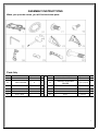
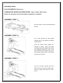
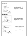
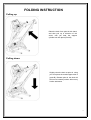
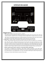
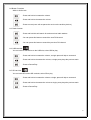
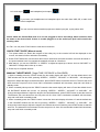
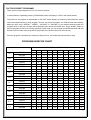
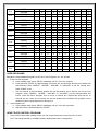
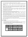
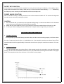
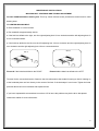
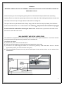
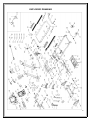
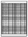
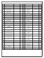
F80 Treadmill
Operating Instructions Manual
Special tips:
1.
2.
Before installation and operation, please read this operation manual carefully.
Please save this manual for future reference.
3.
Product may vary slightly from the item pictured due to model upgrades
IMPORTANT SAFETY INSTRUCTIONS
WARNING - Read all instructions before using this treadmill. It is important your treadmill
receives regular maintenance to prolong its working life. Failing to regularly maintain your
treadmill may void your warranty.
Danger–To reduce the risk of electric shock disconnect your treadmill from the electrical outlet prior to
cleaning and/or service work.
DO NOT USE AN EXTENSION CORD: DON’T ATTEMPT TO DISABLE THE GROUNDED PLUG BY
USING ADAPTERS OR IN ANY WAY MODIFY THE CORD SET.
1) Install the treadmill on a solid flat level surface with nearby access to a power outlet (correct
voltage, frequency and grounded).
2) Do not operate treadmill on deeply padded, plush or shag carpet. Damage to both carpet and
treadmill may result. Rubber Equipment mats are recommended on this type of surface.
3) Do not block the rear of the treadmill. Provide a minimum of 1 metre clearance between the rear of
the treadmill and any fixed object.
4) Never allow children to play on or near the treadmill.
5) When using the treadmill, make sure the plastic clip of the safety key is fastened on your clothing.
It is for your safety, should you fall or move too far back on the treadmill during use.
6) Keep hands away from all moving parts.
7) Never operate the treadmill if it has a damaged cord or plug.
8) Keep the cord away from heated surfaces.
9) Do not operate where aerosol spray products are being used or where oxygen is being
administered. Sparks from the motor may ignite in a highly flammable environment.
10) Never drop or insert any object into any openings.
11) The treadmill is designed and intended for in-home use only and not suitable for long periods of
running (Maximum program time is 99:59 minutes).
12) To ensure disconnection, turn all controls to the off position, remove the safety key, and then
remove the plug from the outlet.
13) The pulse sensors are not medical devices. Various factors, including the user’s movement, skin
type and external interferences may affect the accuracy of heart rate readings. The pulse sensors
are intended only as exercise aids in determining heart rate trends in general.
14) Use handrails provided; they are for your safety.
15) Wear proper shoes. High heels, dress shoes, sandals or bare feet are not suitable for use on your
treadmill. Quality athletic shoes are recommended to avoid leg fatigue.
16) Temperature use range from 5 to 40 degrees Celsius.
Remove the safety key after use to prevent unauthorised treadmill operation.
1
IMPORTANT ELECTRICAL INFORMATION
WARNING!
1) NEVER use a ground fault circuit interrupt (RCD) wall outlet with this treadmill. Route the power
cord away from any moving part of the treadmill including the elevation mechanism and transport
wheels.
2) NEVER operate treadmill on a Generator or UPS power supply.
3) NEVER remove any cover without first disconnecting AC power.
4) NEVER expose this treadmill to rain or moisture. This treadmill is not designed for use outdoors,
near a pool, or in any other high humidity environment.
IMPORTANT OPERATION INSTRUCTIONS
1) Insert the power plug into the wall socket directly. Do not use adapters or extension cords.
2) Be sure to read the entire manual before operating your machine.
3) Understand that changes in speed and incline do not occur immediately. Set your desired speed
on the computer console and release the adjustment key. The computer will respond to the
command gradually.
4) Use caution while participating in other activities while walking on your treadmill; such as watching
television, reading etc. These distractions may cause you to lose balance or stray from walking in
the centre of the belt; which may result in serious injury.
5) In order to prevent losing balance and suffering unexpected injury, NEVER mount or dismount the
treadmill while the belt is moving. To mount the treadmill stand on the side-rails press start the unit
starts at a very low speed step onto the moving belt while it is moving at this speed. Always hold
on to handrail while making control changes.
6) A safety key is provided with this machine it is recommended to always attach the safety key to the
user while using the treadmill. Removal of the safety key will stop the walking belt immediately; the
treadmill will shut off automatically. Inserting the safety key will reset the treadmill.
7) Do not use excessive pressure on console control keys. They are easily damaged by excessive
force.
8) This appliance is not intended for use by persons (including children) with reduced physical,
sensory or mental capabilities, or lack of experience and knowledge, unless they are supervised
by a person responsible for their safety, Children should be supervised to ensure that they do not
play with the appliance.
9) Please consult your doctor at first before running, if any of the following conditions apply to you:
a) Cardiovascular illnesses, high blood pressure, diabetes, respiratory illnesses, and other
chronic ailments or complications from these.
b) If you are over 35 years old and heavier than average weight.
c) Pregnant or breast-feeding mothers.
10) Please stop exercising immediately and consult your doctor if you feel lightheaded or you
experience and other aches and pains.
11) Drink adequate water after exercise to rehydrate.
2
ASSEMBLY INSTRUCTIONS
When you open the carton, you will find the below parts:
Parts list:
NO.
DES.
1
MAIN FRAME
97
LOCK WASHER
Specification Nos.
NO.
DES.
Specification Nos.
1
32
5#ALLEN WRENCH
5MM
1
8
10
33
WRENCH W/SCREW
DRIVER
S=13,14,15
1
77
BOLT
M8*15
10
23
LEFT UPRIGHT TUBE COVER
1
90
BOLT
M5*12
8
24
RIGHT UPRIGHT TUBE COVER
1
118
LEFT BAR
1
119
BOLT COVER
2
117
RIGHT BAR
1
81
BOLT
M8*50
4
3
Assembly Tools:
#5 ALLEN WRENCH: 5mm 1pcs.
COMBINATION WRENCH W/SCRW DRIVER: 13mm, 14mm, 15mm 1pcs.
Notice: Do not power up the unit before assembly is complete.
ASSEMBLY STEP 1:
Open the carton,remove all the parts from
the box.
ASSEMBLY STEP 2:
Lift up the Console (A) and upright
supports (B) in the direction indicated
by the arrows.
Note: Be careful when putting the
Console in place. There are wires
running through the uprights when lifting
the assembly ensure the wire is not
being pinched. Hold uprights to prevent
the console falling until it has been
secured as per step 3
ASSEMBLY STEP 3:
Use the 5# Allen wrench (32) and
M8*15 bolt (77) and lock washer (97),
lock the upright tube (B) onto main
frame.
4
ASSEMBLY STEP 4:
Use the 5# Allen wrench (32) and M8*15
bolt (77) and lock washer (97), lock the
console (A) onto the left and right upright
tube (B).
ASSEMBLY STEP 5:
Fix the Left & Right upright tube covers
(23,24) to the base frame by using
wrench w/screw driver (33) and M5*12
bolt (90).
ASSEMBLY STEP 6:
1.Fix the Left & Right bars(118,117) to
the console by using 5# Allen
wrench(32) and M8*50 bolt (124).
2. Fix the bolt cover (119) to the console
by using wrench w/screw driver (33) and
M5*12 bolt (90).
5
FOLDING INSTRUCTION
Pulling up:
A
Raise the deck from point A with hand,
and then pull up in direction of the
arrow, until you hear the support
cylinder lock into place (Point B)
B
Pulling down:
A
Slightly raise the deck at point A. using
your foot press the metal support tube in
(point B). Release point A. the deck will
fall into its lowered position without any
further assistance
B
6
GROUNDING METHODS
This product must be grounded. Should it malfunction or breakdown, grounding provides a path of
least resistance for electric current to reduce the risk of electric shock. This product is equipped with
a cord having an equipment-grounding conductor and a grounding plug. The plug must be plugged
into an appropriate outlet that is properly installed and grounded in accordance with all local codes
and ordinances.
DANGER – Improper connection of the equipment-grounding conductor can result in a risk of
electric shock. Do not modify the plug provided with the product. This product is for use on a nominal
240-volt circuit and has a grounding plug. No adapter should be used with this product.
7
OPERATION GUIDE
WINDOW DISPLAY:
1. “TIME” window: Displays running time (minutes : seconds).
In modes where a time target has not been specifically set the display will count up from 0:00. If the count
reaches 99:59 the machine will turn off slowing the belt smoothly and the console will return to its initial
state. When a time has been preset the count will decrease from the preset to 0:00. Once 0:00 is reached
the machine will slow down and then stop and the console will return to its initial state.
2. “DIS. & PUL.” window: Shows both Distance (kilometers) and Pulse (beats per minute),
Unless a preset distance target has been entered the window will show the distance in km counting up
from 0.00 to 99.9. When a distance has been preset it will count down show from the distance set to 0.00;
When 0.00 is reached, the machine will stop smoothly, show ‘End’ on the display and enter into its initial
state after a further 5 seconds. To display the runner’s heartbeat the runner holds handle pulse grips with
two hands, the system will calculate the runner’s heart beat and show in this window. The range is 50-200
beats/min. While in startup mode the window will show the program information P1-P24, U1-U3 or FAT.
Please note this data is just for reference, it cannot be used as medical data.
The accuracy of readings can be affected by many factors including conductivity of the users hands,
strength of the users own electrical signal, cleanliness of the sensors and external interference to name a
few. Unfortunately for some people there is no way of accurately measuring their pulse using this type of
technology. A heart rate belt and watch may be a better option.
8
4. “CAL. & INCL.” window: Scans between Calories and the Incline level
Displays user calories burnt. It will count from 0 to 999; unless a target value has been preset. When a
count of 999 has been reached with will start again from 0. If a target Calorie value has been set the prior
to the workout the count will begin at the target value and count down, when it reaches 0, the machine will
slow down and come smoothly to a stop. Current level of incline will be displayed level 0-15.
Please note: Calories burned is indicative only and for reference use only.
To accurately calculate calories burned there are a large number of factors that need to be taken into
consideration including age, gender, level of fitness. Other manufacturers calculate using different
average figures and user information, this is why there is often a discrepancy between different models of
treadmills.
5. “SPEED” window: Displays the current speed (km/h) during use.
During treadmill use the window will display 1.0-20 km/h. When setting a program the base speed will be
shown in this window.
6. Matrix window: During use the dot matrix display will show the users progress around a 400M track. Once
the track is complete the unit will beep once and the track will restart. The window will show program
information while setting one of the preset programs.
BUTTON FUNCTION:
1. “PROGRAM (PROG.)” Button:
In standby mode, press this button to choose “P1-P24…U1-U2-U3 -FAT”.
2. “START” button:With the power switch on and the safety key in place on the console, press this button and
the machine will start. There will be a beep and the machine will start counting down from 3. Once 0 is
reached the walking belt will start moving.
3. “STOP” button: Press this button to stop the machine;
4. “SPEED+”, “SPEED-” Buttons:While in standby mode these buttons will adjust values while the treadmill is
running they will adjust the speed up and down.
5. “INCLINE^”, “INCLINEv” Button: While in standby mode these buttons will adjust values while the treadmill
is running they will adjust the incline up and down.
6. Quick select incline buttons: Low (level 3), Medium (level 6), and High (level 9) pressing these buttons will
quickly set the incline level of the treadmill.
7. Quick select speed buttons: Fast (speed 9), Medium (speed 6), Slow (speed 3) pressing these buttons will
quickly set the speed of the treadmill.
8. Entertainment functions:
8.1 Input select:
This button selects the input for the inbuilt entertainment system. Pressing this button allows
selection between: iPhone/iPad or external device plugged into the 3.5mm audio input jack (AUX), USB
(USB), SD (SD) and Radio. If there is no USB or SD device installed, you can only choose between
iPhone/iPad and Radio.
9
8.2 Button Functions
While in AUX mode
: Press and hold to increase the volume
: Press and hold to decrease the volume
: Press to mute (note: will not pause the music on the auxiliary device.)
8.3: Radio function
: Press and hold this will search for and store local radio stations
: You can press this button to search the next FM channel.
: You can press this button to search the previous FM channel.
8.4: USB card slot
:
You can insert a USB device to the USB slot, select USB to play.
: Press and hold to increase the volume; a single press will skip to next track
: Press and hold to decrease the volume; a single press plays the previous track
: Press to Pause/Play
8.5: SD card slot
:
You can insert SD card to SD card slot, select SD to play.
: Press and hold to increase the volume a single; press will skip to next track
: Press and hold to decrease the volume a single; press plays the previous track
: Press to Pause/Play
10
8.6: Audio input
and headphone jack output;
If you insert your headphones into headphone jack, the audio from USB, SD, or radio it will
transfer to the headphones.
You can connect external audio equipment to Audio input jack, to play select AUX
Notice: While the iPhone/iPad dock is in use the plugged in device will charge, Music selection must
be made on the device itself. If there is a cable plugged in to the audio input jack it will override the
docking cable.
9.0 Fan: You can press “FAN” button to start the on-board fan.
QUICK START GUIDE (Manual mode)
1. Turn power switch on; attach the magnet of the safety key to the console 0.00 will be displayed on the
screen, this state is further referred to as standby.
2. Press START button the unit will count down from 3 the buzzer will make sound the count will be shown in
the speed window once 0 is reached the treadmill will start at 1.0km/hour.
3. After start-up, you can use “SPEED+” or “SPEED-” to adjust the speed up or down, and use “INCLINE^” or
“INCLINEv” to adjust the incline up or down.
4. Press stop to complete workout.
MANUAL TARGET MODE: (Target TIME, DISTANCE or CALORIES)
1. While in standby press the “PROG” button the dot matrix display will show a T and the default time in the
TIME window will now be 15:00; pressing “SPEED+”, “SPEED-”, “INCLINE^” or “INCLINEv” will change the
target time. Adjust the target to the desired time; press START button to start the work out. The time will count
down from the set point to 0:00. Once 0:00 is reached the treadmill will slow down, stop and it will finish in
standby mode.
2. While in standby twice press the “PROG” button the dot matrix display will show a D and the default time in
the DISTANCE window will now be 1.0; pressing “SPEED+”, “SPEED-”, “INCLINE^” or “INCLINEv” will
change the target distance. Adjust the target to the desired distance; press START button to start the work out.
The distance will count down from the set point to 0.00. Once 0.00 is reached the treadmill will slow down,
stop and it will finish in standby mode.
3. While in standby press the “PROG” button 3 times the dot matrix display will show a C and the default time
in the CALORIE window will now be 50; pressing “SPEED+”, “SPEED-”, “INCLINE^” or “INCLINEv” will
change the Calorie target. Adjust the target to the desired amount of Calories; press START button to start the
work out. The distance will count down from the set point to 0. Once 0 is reached the treadmill will slow down,
stop and it will finish in standby mode.
11
FACTORY PRESET PROGRAMS
There are 24 preset programs from P1-P24 for this machine.
In initial situation, repeatedly pressing “PROGRAM” button will display P1-P24 in the speed window.
The profile for the program is represented on the DOT matrix display; the following chart shows the preset
incline and speed values for each program. Choose your desired program, the TIME window start blinking.
Adjust the time using “SPEED+”, “SPEED-”, “INCLINE^” or “INCLINE” to your desired workout length the
program which is split into 10 steps will be divided evenly across the chosen time. Press “START” button to
start the program you have set. During operation of each step, you can change the SPEED and INCLINE, but
be aware the next step in the program will jump back to the preset values set at the factory.
Once the program is complete the console will beep 3 times, the treadmill will slow and then stop.
PROGRAM EXERCISE CHART
TIME INTERVAL=SETTING TIME/10
P1
P2
P3
P4
P5
P6
P7
P8
P9
P10
P11
P12
1
2
3
4
5
6
7
8
9
10
SPEED
2
4
3
4
3
5
4
2
5
3
INCLINE
1
2
3
3
1
2
2
3
2
2
SPEED
2
5
4
6
4
6
4
2
4
2
INCLINE
1
2
3
3
2
2
3
4
2
2
SPEED
2
5
4
5
4
5
4
2
3
2
INCLINE
1
2
2
3
1
2
2
2
2
1
SPEED
3
6
7
5
8
5
9
6
4
3
INCLINE
2
2
3
3
2
2
4
6
2
2
SPEED
3
6
7
5
8
6
7
6
4
3
INCLINE
1
2
4
3
2
2
4
5
2
1
SPEED
2
8
6
4
5
9
7
5
4
3
INCLINE
2
2
6
2
3
4
2
2
2
1
SPEED
2
6
7
4
4
7
4
2
4
2
INCLINE
4
5
6
6
9
9
10
12
6
3
SPEED
2
4
6
8
7
8
6
2
3
2
INCLINE
3
5
4
4
3
4
4
3
3
2
SPEED
2
4
5
5
6
5
6
3
3
2
INCLINE
3
5
3
4
2
3
4
2
3
2
SPEED
2
3
5
3
3
5
3
6
3
3
INCLINE
4
4
3
6
7
8
8
6
3
3
SPEED
2
5
8
10
6
9
5
3
2
2
INCLINE
1
3
5
8
10
7
6
3
2
3
SPEED
2
5
5
4
4
6
4
2
3
4
INCLINE
3
5
6
7
12
9
11
11
6
3
12
P13
P14
P15
P16
P17
P18
P19
P20
P21
P22
P23
P24
SPEED
2
7
4
7
8
9
4
5
3
2
INCLINE
5
6
6
4
6
5
8
9
4
2
SPEED
2
6
5
4
8
6
5
2
3
3
INCLINE
5
6
5
8
4
5
5
10
6
3
SPEED
2
6
5
4
8
7
5
3
3
2
INCLINE
3
4
5
6
3
5
5
6
4
3
SPEED
2
5
7
5
8
6
5
2
4
2
INCLINE
1
5
6
8
12
9
10
9
5
3
SPEED
2
5
6
7
8
9
10
5
3
4
INCLINE
3
5
6
8
6
5
8
7
5
3
SPEED
2
3
5
6
8
6
9
6
5
2
INCLINE
5
7
5
8
6
5
9
10
6
2
SPEED
3
7
6
5
9
7
6
3
5
2
INCLINE
3
5
6
8
5
6
5
12
8
3
SPEED
3
7
9
10
11
12
10
8
5
2
INCLINE
2
5
6
7
6
5
8
6
3
2
SPEED
3
6
8
7
9
10
5
8
3
2
INCLINE
3
6
8
9
9
6
8
10
6
3
SPEED
3
5
8
6
9
10
8
12
6
3
INCLINE
2
6
8
10
12
10
12
8
5
2
SPEED
3
5
9
11
12
8
6
5
3
2
INCLINE
2
6
8
10
9
7
8
10
6
3
SPEED
3
8
10
11
12
10
10
8
5
3
INCLINE
3
6
8
9
10
12
9
6
3
2
USER PROGRAMS
Besides the 24 preinstalled programs, there are 3 User Programs: U1, U2, and U3
1. To save a User Program:
a. In the standby state, press “PROG” repeatedly until U1, U2 or U3 is shown.
b. Press and hold “PROG” for approximately 3 seconds, the unit will beep and the time window will
start blinking. Press “SPEED+”, “SPEED-”, “INCLINE^” or “INCLINEv” to set the running time;
press “PROG” to set.
c. The first interval in the Dot Matrix window will now be blinking, this is interval one for the user
program. Using “SPEED+”, “SPEED-”, “INCLINE^” or “INCLINEv” set the desired speed and
incline. Once set Press “Program once to move to interval two. Repeat this step until all 10
intervals are set. Once all 10 intervals are set the treadmill will remember this program unless
another workout is programmed over the top of it.
2. User Program use:
a. In the standby state, press “PROG” repeatedly until U1, U2 or U3 are shown.
b. Adjust the time if desired and press “START”.
HEART RATE CONTROL PROGRAM:
1.
Press “HRC”button under standby mode, you can choose heart rate control from HP1 to HP2.
HP1: The max speed will be 10.0KM/H,and the default heart rate is 114hypo/min.
13
HP2: The max speed will be 12.0KM/H,and the default heart rate is 114hypo/min.
2.
Press “MODE” button to enter age setting.Time window will show default age of 30.Owner can press
“INCLINE+”、“INCLINE -”、“SPEED+”、“SPEED -” button to choose actual age, and age range is from 15
to 80 years old.
3.
After owner finish choice of age, press “MODE” button, system will recomand a suitable target hear rate
and show in screen for owner’s reference. Owner can also press “INCLINE+”、“INCLINE -”、“SPEED+”、
“SPEED -” button to choose expected target heart rate according to owner’s physical condition, and
available option range is from 84 to195.
4.
After owner finish opition of age and target heart rate, press “MODE” to enter time setting. “TIME”window
will show preset time of 10:00, press “INCLINE+”、“INCLINE -”、“SPEED+”、“SPEED -”button to adjust time,
and available range is from 10:00 to 99:00.
5.
Press “START” button directly to start up.
6.
Under HRC mode, if you do not set any value and press “START” button directly, the system will adjust
speed and incline automatically as per the default target heart rate value.
7.
Under the operation of HRC program, “INCLINE+”、“INCLINE -”、“SPEED+”、“SPEED -”buttons are
available to adjust speed and incline, but the system can also adjust speed and incline automatically to
achieve owner’s target heart rate value.
8.
The first 1 min of your running is warm-up, the system will not adjust speed and incline automatically, only
manual adjustment is available in the first min.After 1 min, the system will add speed under frequency of
0.5km each time, when the value reachs the max speed, and still does not achieved target heart rate
value, system will add incline with frequency of 1 section each time in order to reach owner’s target heart
rate value, when the setting time finish, the machine will stop automatically
9.
Note: Heart rate control program can only be available when chest belt is used, and chest belt must put
closely to chest and skin.
BODY TESTER:
1. In the standby state, press “PROG” repeatedly until FAT is displayed.
2. Press and hold “PROG” for approximately 3 seconds the display will show F1. Using the table below
enter all the data using the “SPEED+” and “SPEED-“ keys followed by “PROG” to set.
3. Once F5 has been entered hold onto the pulse grips. The treadmill will then calculate your index figure.
Your result can be used in the table below.
F-1
F-2
F-3
F-4
Sex
01 male
02 female
Age
10------99
Height
100----200
Weight
20-----150
FAT
≤19
Underweight
FAT
=(20---25)
Normal weight
F-5
FAT
=(26---29)
Overweight
FAT
≥30
Obese
(PLEASE NOTE: This data is just for reference, cannot be used as medical data.)
14
SAFETY KEY FUNCTION:
If the safety key is removed while the treadmill is running the belt will stop immediately. In the standby state it
will prevent the treadmill from starting. While the key is removed all the windows display “―――”. Reattaching
the safety key to the console put the treadmill back into its standby mode.
POWER SAVING FUNCTION:
After 10 minutes of sitting in standby idle the screen of the console will switch off. The screen will relight and
normal function resume by pressing any button.
CAUTION:
1. We recommend that you maintain a slow speed at the beginning of a workout and hold on to the handrails
until you become comfortable and familiar with the treadmill.
2. Attach the clip of the safety key rope to your clothing to ensure the treadmill shuts off should you fall.
3. To end your workout safely, press the STOP button to stop the belt moving before you dismount.
EXERCISE INSTRUCTIONS
1. The Warm Up Phase
This stage helps get the blood flowing around the body and the muscles working properly. It will also reduce
the risk of cramp and muscle injury. It is advisable to do a few stretching exercises as shown below. Each
stretch should be held for approximately 30 seconds, do not force or jerk your muscles into a stretch - if it hurts,
STOP.
2. The Exercise Phase
This is the stage where you put the effort in. After regular exercise, the muscles in your legs will become
stronger. The level of work should be sufficient to raise your heart beat into the target zone shown on the graph
below. This stage should last for a minimum of 12 minutes for most people.
15
3. The Cool Down Phase
This stage is to let your Cardio-vascular System and muscles wind down. This is a repeat of the warm up
exercise e.g. reduce your tempo, continue for approximately 5 minutes. The stretching exercises should now
be repeated, again remembering not to force or jerk your muscles into the stretch.
As you get fitter you may need to train longer and harder. It is advisable to train at least three times a week,
and if possible space your workouts evenly throughout the week.
Maintenance
Reasonable cleaning/lubricating should be undertaken to extend the life time of this unit. Performance is
maximized when the belt and mat are kept as clean as possible.
WARNING: THE MAT/DECK FRICTION MAY PLAY A MAJOR ROLE IN THE FUNCTION AND LIFE OF YOUR TREADMILL.
FOR THESE REASONS WE RECOMMEND YOU REGULARLY LUBRICATE THESS FRICTION POINTS TO PROLONG THE
USEFUL LIFE OF YOUR TREADMILL. FAILING TO DO THIS MAY VOID YOUR WARRANTY.
WARNING: ALWAYS UNPLUG POWER CORD BEFORE MAINTENANCE.
WARNING: STOP TREADMILL BEFORE FOLDING.
Maintenance and servicing
AFTER EACH USE (DAILY)
Clean and inspect, following these steps:
1) Turn off the treadmill with the on/off switch, and then unplug the power cord at the wall outlet.
2) Wipe down the running belt, deck, motor cover, and console casing with a damp cloth. Never use
solvents, as they can cause damage to the treadmill.
3) Inspect the power cord.
4) Make sure the power cord is not underneath the treadmill or in any other area where it can
become pinched or cut.
5) Check the tension and alignment of the running belt. Make sure that the treadmill belt is not
damaging any other components on the treadmill by being misaligned.
16
EVERY WEEK
Clean underneath the treadmill, following these steps:
1) Turn off the treadmill with the star/stop switch, and then unplug the power cord at the wall outlet.
2) Fold the treadmill into the upright position, making sure that the lock latch is secure.
3) Wipe or vacuum any dust particles or other objects that may have accumulated underneath the
treadmill.
EVERY MONTH -IMPORTANT!
Belt/Deck/Roller Lubrication
The mat/deck friction may play a major role in the function and life of your treadmill and that is why we
recommend you regularly lubricate this friction point to prolong the useful life of your treadmill.
You should apply the lubrication after approximately the first 20 hours of operation. We recommend
checking of the deck every 30 days.
How to check the running mat for proper lubrication:
1.
Disconnect the main power supply.
2.
Fold the treadmill up into the storage position.
3.
Feel the back surface of the running mat.
If the surface is slick when touched, then no further lubrication is needed.
If the surface is dry to the touch, apply a suitable silicone lubricant.
This can be purchased from your local hardware store.
Lubrication instuctions below.
Please also check all assembly bolts are tight
EVERY 6 MONTHS
It may be necessary to lubricate your treadmill running deck at least once every six months to maintain
optimal performance of your treadmill.
1) Turn off the treadmill with the start/stop switch, and then unplug the power cord at the wall outlet.
2) Leave the treadmill for 15 mintues. Remove motor cover and vacuum any dust or lint out of the
motor area.
3) Lubricate the air shocks with Teflon based spray.
17
MAINTENANCE INSTRUCTIONS
WALKING BELT CENTERING AND TENSION ADJUSTMENT
DO NOT OVERTIGHTEN the walking belt. This may cause reduced motor performance and excessive roller
bearing wear.
TO CENTER WALKING BELT:
● Place treadmill on a level surface
● Run treadmill at approximately 4km/hr
● If the belt has drifted to the right, turn the right adjusting bolt 1/2 turn clockwise and the left adjusting bolt 1/2
a turn counterclockwise.
● If the belt has drifted to the left, turn the left adjusting bolt 1/2 turn clockwise and the right adjusting bolt 1/2
turn clockwise and the right adjusting bolt 1/2 turn counterclockwise.
PIC A
Picture A If the belts has drifted to the RIGHT
PIC B
Picture B If the belts has drifted to the LEFT
To check for the correct belt tension: Stand on the side rails and set the treadmill running to 4km/h. Holding on
to the handrails plant one foot directly in the centre of the belt. If the belt stops it is too loose. Tighten the bolts
pictured about half a turn clockwise and repeat the test.
If you have repeated this test and done more than 2.5 full turns the problem may be the drive belt please
contact the retailer for more information.
18
CLEANING
WARNING: ALWAYS UNPLUG THE TREADMILL FROM THE ELECTRICAL OUTLET BEFORE CLEANING OR
SERVICING THE UNIT.
General cleaning or the unit will greatly prolong the life of the treadmill. Keep treadmill clean by dusting
regularly. Be sure to clean the exposed part of the deck on either side of the walking belt and also the side rails.
This reduces the build-up of foreign material underneath the walking belt.
The top of the belt may be cleaned with a damp, soapy cloth. Be careful to keep liquid away from inside the
motorized treadmill frame or from underneath the belt. Warning:Always ensure the treadmill is unplugged
from the electrical outlet before removing the motor cover. At least once a year remove the motor cover
and vacuum under the motor cover.
WALKING BELT AND DECK LUBRICATION
The treadmill is equipped with lubricated running board, which needs regular maintenance. The friction between
running board and running belt has a great effect on the treadmills’ life.
The steps are as follows:
a) Remove the power cord from the wall socket.
b) Wipe out the dust between running board and running belt with a clean cloth.
c) As shown in the picture apply the Silicon oil on the running board (2 small daubs about 50mm in diameter
approximately where your feet hit the deck during use).
d) Plug the treadmill back and set running to the lowest speed. Slowly walk the silicon over the surface of the
treadmill deck.
19
EXPLODED DRAWING
20
PARTS LIST
NO.
DESCRIPTION
1
Q’TY
NO.
DESCRIPTION
BASE FRAME
1
63
CONSOLE ARCYLIC
1
2
MAIN FRAME
1
64
SAFETY KEY TRAY
1
3
INCLINE FRAME
1
4
CONSOLE FRAME
1
66
SPEAKER
2
5
MOTOR BRACKET
1
6
LEFT UPRIGHT TUBE
1
68
RUBBER MAT
1
7
RIGHT UPRIGHT TUBE
1
69
BOLT
ST3.5*10
8
8
FAN
1
70
BOLT
M6*15
2
9
FAN GUIDE TUBE
1
71
HEX
M8
6
10
FRONT ROLLER
1
72
HEX
M10
6
11
BACK ROLLER
1
73
HEX
M8
8
12
CYLINDER
1
74
ALLEN
M10*30
4
13
BUSHING
4
75
ALLEN
M10*45 L20
1
14
PLASTIC PAD
4
76
ALLEN
M10*60 L20
1
4
77
ALLEN
M8*15
12
TRANSPORT WHEEL
SPECIFICATION
SPECIFICATION
Q’TY
15
PLUG
16
TRANSPORT WHEEL
2
78
ALLEN
M8*20
4
17
RUNNING BOARD
1
79
ALLEN
M8*30 L15
1
18
PCB BOARD
1
80
ALLEN
M8*40 L 20
2
19
MAGNET RING
1
81
ALLEN
M8*50 L 20
6
20
MAGNET CORE
1
82
ALLEN
M8*70 L 20
2
1
83
ALLEN
M8*80 L 20
2
1
84
ALLEN
1
85
ALLEN
M8*40
1
1
86
ALLEN
M6*55
3
M6*25
6
COMPUTER BOTTOM
21
COVER UP
COMPUTER BOTTOM
22
COVER DOWN
LEFT UPRIGHT TUBE
23
COVER
RIGHT UPRIGHT TUBE
M8*30
1
24
COVER
25
LEFT BACK END COVER
1
87
ALLEN
26
RIGHT BACK END COVER
1
88
ALLEN
27
MOTOR TOP COVER
1
89
BOLT
M5*16
6
28
MOTOR BOTTON COVER
1
90
BOLT
M5*12
8
29
CUSHION
2
91
SCREW
ST4.2*12
12
30
SIDE RAIL
2
92
SCREW
ST4.2*12
35
31
NONE-SLIP MAT
2
93
SCREW
ST2.9*8
2
32
5# ALLEN WRENCH
1
94
SCREW
ST2.9*6.5
12
95
SCREW
ST4.2*15
96
LOCK WASHER
WRENCH W/SCREW
33
DRIVER
1
34
PIPE PLUG
2
M6*40
6
2
6
3
21
35
AC SINGLE WIRE
2
97
LOCK WASHER
8
16
36
AC SINGLE WIRE
2
98
LOCK WASHER
10
2
37
SAFETY KEY
1
99
SPRING WAHSER
8
6
38
GROUNDING WIRE
1
100
FLAT WASHER C
39
POWER WIRE
1
101
1
102
SCREW WITH
WASHER
8
M5*8
MOTOR TOP COVER
7
13
1
40
POWER OUTLET
41
SQUARE SWITCH
1
103
BIG WASHER C
42
OVERLOAD PROTECTOR
1
104
ALLEN
M8*42 L20
1
43
INCLINE MOTOR
1
105
SCREW
ST4.2*20
6
44
MCB BOARD
1
106
45
RUNNING BELT
1
107
46
MOTOR BELT
47
FOAM COVER
48
SPEED SENSOR
1
50
51
CUSHION
BLUE RUBBR CUSHION
52
BLUE RUBBR CUSHION
53
ADJUSTABLE WHEEL
54
CONE-SHAPE CUSHION
55
FLAT FOOT PAD
WIRE PROTECTOR
56
10*Φ26*2.0
TOP SIGNAL WIRE
8
1
BOTTOM SIGNAL
108
WIRE
2
109
FLITER
OPTIONAL
1
1
110
INDUCTANCE
OPTIONAL
1
111
WIRE COVER
49
BLACK RUBBER
ARCYLIC
4
2
2
2
2
6
2
1
1
PULSE SUPPORTING
112
TUBE
2
SPEED PULSE TOP
113
COVER
1
SPEED PULSE
114
BOTTOM COVER
1
INCLINE PULSE TOP
115
COVER
116
BOTTOM COVER
1
INCLINE PULSE
1
SPEED PULSE END
117
CAP
1
INCLINE PULSE END
118
CAP
1
57
THREAD AXLE
2
119
BOLT COVER
2
58
Z-SHAPED BOARD
2
120
PULSE IRON SHEET
4
DC MOTOR
59
CONSOLE BOTTOM
1
1
60
COVER
61
CONSOLE TOP COVER
1
62
CONSOLE PANEL
1
SAFETY KEY
121
COPPER SHEET
1
SAFETY KEY SPRING
122
SHEET
123
SCREW
2
ST4.2*40
2
22
1) TROUBLE SHOOTING GUIDE
1) If the console doesn’t light up after the power has been turned on the most likely cause is that the wire
running up the upright arm has been damaged during assembly or is not plugged in correctly. Please
check the cable and connections.
Check the overload button; located beside the power switch, if the overload protector button has
triggered, please press this button.
2) E01: Communications failure. Probable cause: The wires from console and motor control board are not
connected well, please check each plug. If the wire is damaged, replace it.
FOR THE BELOW CONDITIONS PLEASE CONTACT RETAILER FOR FUTHER INFO.
3) E02: Surge Protection. Ensure the treadmill is plugged into a 230V socket. Test in new socket if still not
going the bottom control board is possibly damaged please contact reailer.
4) E03: No speed sensor signal. If the motor runs for a few seconds and then brings up the E3 error there
is a problem with the feedback from the speed sensor. Please contact retailer for detailed instructions
on how to check.
5) E04 or E06 Incline: Please check all wires running from the incline motor they should be well seated try
unplugging and plugging them back in. Contact Retail if this doesn’t resolve the problem
6) E05: Current Overload protection. Either the unit is over the rated load or the motor is stuck, causing
excessive current. Turn the unit off and check the belt rotates freely the try restart if the problem
persists contact the retailer. It is possible the motor or bottom control board have failed.
7) E07: Communication problems. The wires from console and motor control board are not connected
well or the wire is damaged, please check each plug. If the wire is damaged, replace it
8) E08: Control Board Failure: Contact retailer
9) E09: Check the deck has been correctly lowered
10) The motor will not start after pressing “START” button. There are several possible reasons:
a. The motor wire is broken or disconnected;
b.The fuse is blown;
Test the above reasons, if it is not one of these contact the retailer.
23