1
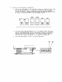
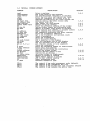
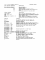
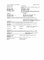
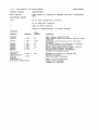
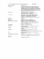
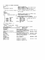
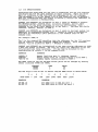
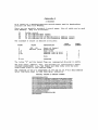
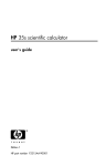
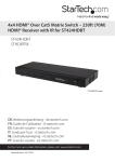
MACSbug 68000
DEBUGGER USER'S GUIDE
THE CORVUS CONCEPT
***CORVUS SYSTEMS
* *
MACSbug 68000
DEBUGGER USER'S GUIDE
THE CORVUS CONCEPT
PART NO.: 7100-01387
DOCUMENT NO.: CCC/60-33/1.1
RELEASE DATE: March, 1983
CORVUS CONCEPT'" is a trademark of Corvus Systems, Inc.
CORVUS CONCEPl'
MACSbug 68000 DEBUGGER
USER'S MANUAL
Much of the information contained in this manual is reprinted with the
permission of Motorola Inc. from the Motorola MC68000 Design Module
User's Guide (Motorola part number MEX68KDM(D4) AUGUST, 1980).
EXORciser and MACSbug are trademarks of Motorola, Inc.
MACSbug
INSTALLATION AND OPERATING INSTRUCTIONS
1.1
INTRODUCTION
This document describes the Corvus Concept MACSbug Debugger Version
2.0. It includes a description of the commands for the resident
firmware monitor, MACSbug, and examples of its use.
1.2
INSTALLATION PROCEDURES
NOTE: Before powering the base unit ON or OFF, ensure that there is no
diskette in the floppy drive.
a)
Power-off the Concept base and display.
b)
Disconnect the keyboard cable and display monitor cable. Open the
drawer of the base unit and remove the power supply cables connected
at locations labeled J8 and Jl on the processor board and the memory
board respectively. Remove any tap cables or interface cards which
are currently in the drawer.
c)
Lift up on the drawer assembly and completely remove it from
the base unit.
d)
The procedure to install MACSbug ROMs is different for REV 03
processor boards and REV 04 processor boards. You can determine
whether you have a REV 03 or REV 04 by the configuration of the
Concept boot switches.
On the REV 03 processor boards, there is a 2-switch microswitch on
the right side of the processor board, opposite the I/O slots.
On the REV 04 processor boar'ds, there is a 8-switch microswitch on
the right side of the processor board, opposite the I/O slots.
e)
Revion 03 Installation Procedures
1.
Locate the Boot ROMS on the processor board at locations U706 (ROH
OU) and 0711 (ROM OL). If they are not version 0.5 or later,
remove the ROMs at these locations and place the ROM labeled CC
0.5 H or later in location U706 and place the ROM labeled CC 0.5 L
or later in location U7ll on the processor board.
U708
U706
U707
Boot
Static
ROM
High
ROM
High
U709
U711
2.
Place the ROM labeled MACSbug 2.0 L in location U709 and place
the ROM labeled MACSbug 2.0 H in location U708 on the processor
board. The MACSbug ROM sockets are 28 pin sockets, and the
MACSbug ROMs are 24 pin devices. The sockets should have the
top four pin locations unused ( i.e. pins 1,2,27 and 28).
3.
Place both microswitches in the ON position.
01'
BOOUwitl:hes
~
f)
Revison 04 Installation Procedures
1.
Locate the Boot ROMS on the processor board at locations U706 (RO'1
OL) and U7l0 (ROM OU). If they are not version 0.5 or later,
remove the ROMs at these locations and place the ROM labeled CC
0.5 R or later in location U710 and place the ROM labeled CC 0.5 L
or later in location U706 on the processor board.
U70B
'0-
ID
...::J
0
Boot
ROM
Low
Static
ROM
Low
U709
'0
MACSbug
MACSbug
Low
High
U710
U711
2.
Place the ROM labeled MACSbug 2.0 L in location U708 and place
the ROM labeled MACSbug 2.0 R in location U709 on the processor
board. The MACSbug ROM sockets are 28 pin sockets, and the
MACSbug ROMs are 24 pin devices. The sockets should have the
top four pin locations unused ( i.e. pins 1,2,27 and 28).
3.
Place microswitches 7 and 8 in the ON position.
g)
Replace the drawer into the base unit and position the two
power supply cables along the speaker tray channel to prevent
chaffing of the cables. Reconnect the power supply cables to
J8 on the processor board and JI on the memory board.
h)
Reconnect any tap cables or interface cards originally within the
drawer.
i)
Power on the display and then the base unit. The Concept will
emit a beep, and then request input from the user regarding
the boot device as follows:
Select the device :
(D,F,L,O) :
D - Debug (MACSbug)
F - Floppy Disk Drive
L - Local Disk Drive
o - Omninet Drive
j)
Select your normal disk boot option to run a quick check of the
unit.
k)
If the unit does not complete the boot, check the ROM locations and
that all pins of the ROMs are installed correctly. Repeat the
procedure until the system boots. If problems persist, contact
your local servicing dealer or Corvus Customer Service.
1.3
COMMMUNICATING WITH MACSbug
Communication with MACSbug is performed through the two serial' ports on
the back of the Corvus Concept. When used with MACSbug, port 1 has a
default data rate of 9600 BAUD. parity is disabled and an 8 bit
character size is assumed. An ASCII terminal must be attached to port
1 with a null modem cable. This terminal is the MACSbug console.
MACSbug supports port 2 as a standard RS-232C data terminal connector
with a default data rate of 4800 BAUD, parity disabled and a 8 bit data
character size. Port 2 can be used to communicate with a host computer,
a printer or other serial device.
This two port communication arrangement allows the Corvus Concept to be
placed in series with an ASCII terminal and a host computer. The
transparant mode in MACSbug can be used to bypass the Corvus Concept.
This allows a program to be created on the host computer using the ASCII
terminal and then when the program code file is generated, it can be
downloaded into the Corvus Concept for execution and dubugging. This
can all be performed without reconfiguring the cabling.
1.4 OPERATIONAL PROCEDURE
After the MACSbug ROMs has been installed, MACSbug can be entered
before the Corvus Concept operating system is booted as follows:
a.
Connect an ASCII terminal to port 1 of the Corvus Concept.
b.
Ensure that the Concept boot switches are both in the ON position.
c.
Power on the Corvus Concept.
d.
Select option D, for Debugger, when prompted.
MACSbug will initialize and display on the ASCII terminal connected to
port 1 with the following message:
MACSBUG 2.0
*
If these two lines do not print out, perform the following:
a.
Check to see that the ASCII terminal is attached to RS-232C
port 1 using a null modem cable.
b.
Ensure that the terminal's BAUD rate is set to 9600. parity is
disabled and an 8 bit character size is selected.
1.5
COMMAND LINE FORMAT
Commands are entered the same as in most other buffer organized computer
systems. A standard input routine controls the system while the user types
a line of input. The delete (RUBOUT) key or control H will delete the
last character entered. A control X will cancel the entire line.
Control D will redisplay the line. Processing begins only after the
carriage return has been entered.
The format of the command line is:
*COmmand parameters :options
where:
is the prompt from the monitor. The user does
not enter this. In the examples given, the lines
beginning with this character are lines where the
user entered a command.
CO
is the necessary input for the command. Each
command has one or two upper case letters
necessary in its syntax. In the examples, the
entire command may be used, but only those
letters in upper case in the syntax definition
are necessary. In actual usage, MACSbug converts
all lower case characters to upper case.
mmand
is the unnecessary part of the command. It is
given in the syntax definiton only to improve
readability. If this part of the command was
actually entered on the command line, it would be
ignored.
parameters
depends upon the particular command. Data is
usually in hex but most printable ASCII
characters may be entered if enclosed in single
quotes. The system also supports a limited
symbolic feature allowing symbols to be used
interchangeably with data values.
:options
modifies the nature of the command. A typical
option might be to disregard the checksum while
downloading.
1.6
MACSbug
COMMAND SUMMARY
DESCRIPTION
COMMAND
regl
reg' hexdata
regl 'ASCII'
reg':
class
class:
DM start end
SM address data
OPen address
SYmbol NAME value
WI
WI. len EA
MI data
Go
Go address
Go TILL add
BReakpoint
BR add: count
BR -address
BR CLEAR
TD
TD regl.format
TD Clear
TD ALI
TD A.l D.l L.c
*•• data
Print a register
Put a hex value in the register
Put hex-equivalent characters in register
Print the old value and request new value
Print all registers of a class (A or D)
Sequence through-print old value request new
Display memory, hex-ASCII memory dump
Set memory with data
Open memory for read/change
Define and print symbols
Print the effective address of the window
Define window length and addressing mode
Memory in window. same syntax as register
Start running from address in program counter
Start running from this address
Set temporary breakpoint and start running
Print all breakpoint addresses
Set a new breakpoint and optional count
Clear a breakpoint
Clear all breakpoints
Print the trace display
Put a register in the display
Take all registers out of the display
Set all registers out of the display
Set register blocks or line separator
Trace one instruction
Trace the specified number of instructions
Trace until this address
Carriage return-trace one instruction
Define the global offset
Convert decimal number to hex
Convert hex to decimal
calculate offset or displacement
Expect to receive S records
Check memory against S records
JSR to user utility routine
Enter transparent mode
Transmit command to host
CTL-A
CTL-D
CTL-H
CTL-X
The
The
The
The
T
T count
T TILL Address
:*(CR)
OFfset address
CV decimal
CV $hex
CV value, value
REad:=test
VErify:=text
CAll address
P2
control
control
control
control
A
D
H
X
key
key
key
key
SECTION
1.6.1
1.6.2
1.6.3
1.6.4
1.6.5
1.6.6
1. 6.7
1.6.EI
1.6.9
1.6.10
1.6.11
1.6.12
1.6.,13
1.6.)4
ends transparent mode (default)
redisplays the line
deletes the last character entered
cancels the entire line
1.6.1
Set and Oisplay Registers
REGISTER OISPLAY
68000 REGISTER MNEMONICS
OESCRIPTION
00,01,02,03,04,05,06,07
AO,Al,A2,A3,A4.A5,A6,A7
PC
SR
SS
Oata registers
Address registers
Program counter
status register (condition codes)
Supervisor stack pointer (A7 in supervisor
mode)
User stack pointer (A7 in user mode)
US
COMMANO FORMATS
OESCRIPTION
reg' hexdata
reg' 'ascii data'
reg':
reg'
class (where class=O or A)
class:
Put a hex value into register 'reg"
Put hex value of ASCII into register 'reg"
Print register value and request in new value
Print register value
Print values of all registers in the class
Cycle through all registers in the class
printing old value and requesting new value
EXAMPLES
COMMENTS
*A5 123
*A5
A5=00000123
*04 FFFFFF
*00:
00=0000000 ? 45FE
*0:
00=000045FE ? 9EAB3
Set address register A5 to hex value 123
Command to print the value of register AS
Computer response
Set a data register
Command to print old value and take in new value
Computer prompts with old valuel new value entered
Command to cycle through all data registers
Change value of register 00 from 45FE to 9EAB3
01=00000000
(CR)
02=00000000
03=00000000
04=00FFFFFF
05=00000000
06=00000000
07=00000000
*0
00=0009EAB3
04=00FFPPPF
*PC:
PC=0008B3 ?
*SR 0
*A7 4321
*US
US=00004321
*SS PFC
*SR 2000
*A7
A7=00000FFC
? (CR)
Carriage return (null line) means the value
remains the same
? (CR)
? (CR)
? 55555
? (CR)
? (CR)
Change register 05 to a new value
Oisplay all-data registers
01=00000000 02=00000000 03=00000000
05=00055555 06=00000000 07=00000000
Oisplay and request input for program counter
2561
Set the program counter to new value
Set status register to zero (user mode)
Set address register (same as US now)
Oisplay user stack pointer
Set supervisor stack pointer
Set status register to supervisor mode
Print A7 which is now the SS register
Initialize system stack pointer value from
MACSbug
1.6.2
Display and Set Memory
MEMORY DISPLAY
COMMAND FORMAT
DESCRIPTION
OM start end
Display Memory in hex and ASCII where start
< end
Where start > count
Send output to PORT 2
Set Memory to hex
Set Memory to ASCII
The 'N' as the last character means start a
new line: the system will prompt with the
current address
OM start count
DM2 start end
SM address data
SM address 'ASCII'
SM address data N
EXAMPLES
COMMENTS
*SM 92000 'ABC'
*SM 92003 4445 46 'G'
*DM 92000 92010
Set memory to some ASCII data
Set some more locations
Command to dump memory
0092000 41 42 43 44 45 46 47 00 00 00 00 00 00 00 00 00 ABCDEFG •••••••
0092010 00 00 00 00 00 00 00 00 00 00 00 00 00 00 00 00 ••••••••••••••
In the following usage of the DM
command the second number is smaller than
the first so it is decoded as a count.
*DM 92003 12
0092003 44 45 46 47 00 00 00 00 00 00 00 00 00 00 00 00 DEFG ••••••••••
0092013 00 00 00 00 00 00 00 00 00 00 00 00 00 00 00 00 ••••••••••••••
*SM 9100n , ,~ 4~6 7890 ABCDE 12345678 Size can be up to 8 characters
*DM 91000
091000 01 23 04 56 78 90 OA BC DE 12 34 56 78 00 00 00 •••••••••••••••
*SM 91000
'TABLE
00005678 N
0009100C?
'START
00023456
Use of the 'N' parameter to
start a new line
*DM 91000 20
091000 54 41 42 4C 45 20 20 20 00 00 56 78 53 54 41 52 TABLE •••• VxSTAR
091010 54 20 20 20 00 02 34 56 00 00 00 00 00 00 00 00 T••••• 4V ••••••
*OFFSET 2030
Global offset will be added to
*DM 91000
command parameters
093030 FF FF FF FF FF FF FF FF FF FF FF FF FF FF FF FF .............
*SM 91005 1234 N
Global offset added to address 91005
00093037 ? AB
*DM 91noo
093030 FF FF FF FF FF 12 34 AB FF FF FF FF FF FF FF FF ••••••••••••••
*SM 20000 AB CD EF
ERROR
*
Trying to set ROM
Error message
1.6.3
Open Memory for Read/Change
OPEN MEMORY
COMMAND FORMAT
DESCRIPTION
OPen address
Open memory at specified address and enter subcommand
mode
SUBCOMMAND FORMAT
(CR)
Go to next sequential location
Go to previous location
Stay at same location
Return to MACSbug(exit the OPen command)
EXAMPLES
ADDRESS
CONTENT
USER
ENTERS
*OP EOO
OOOEOO
FF?
000E01
AB?
(CR)
000E02
000E01
OOOEOO
OOOEOO
OOOEOO
44?
AB?
12?
34
12
A
77=
77?
77?
*OP 21234
021234
FF?
**NO CHANGE**
021234
FF?
*OP EOO
OOOEOO DO? W
W IS NOT A HEX DIGIT
99=
COMMENTS
Open memory location EOO
User enters data and system goes to next
location
Carriage return means go to the next
location
UP arrow means go to previous location
Can be entered without data
Equal sign means stay at same address
Can be used without any data
Period means return to MACSbug
Returns to command level
Example of trying to change ROM
Warning message
Does not abort command
Enter invalid character
Print error message
Command is aborted
1.6.4
Define and Print Symbols
SYMBOLS
COMMAND FORMAT
DESCRIPTION
SYmbol name hex value
Put a symbol in the symbol table with a hex value
or assign a new value to a previously defined
one. NAME can be 8 characters long, consisting
of:A-Z,0-9,(period), and $(dollar sign). It must
begin with letter (A-Z) or period.
Remove a symbol from the symbol table
Print the current value of the symbol (absolute)
Print the first symbol with the given value
Print the sorted symbol table
SY
SY
SY
SY
-name
name
value
NOTE
Offset is not used by this command. Some commands
recognize the words TILL, ALL. and CLEAR as key words
and will not interpret them as symbols.
EXAMPLES
COMMENTS
·SY XYZ 5000
·SY-XYZ
XYZ=5000
·SY XYZ 123
·SY ABC34 2500
·SY Z17.RT5 XYZ
·SY-123
XYZ=123
·SY B$67ABC 4300
·SY RFLAG 200
·SY MVP2 9990
·SY
ABC34 00002500
RFLAG 00000200
Puts the symbol in the table
Command prints out the symbol's current value
Change a symbol's value
Define another symbol
Define a symbol with value from another symbol
Print first symbol with value of 123
Define some more symbols
Print the sorted symbol table
B$67ABC
00004300
MVP2
00009990
XYZ
00000123
Z17.RT5 00000123
·SY TTT
T IS NOT A HEX DIGIT
·SY 567
00000567 .. 567
Print a value for symbol not in table, when not
found, it tries to convert parameter to number
Attempt to print value for symbol not in table
SYNTAX EXAMPLES
COMMENTS
·BR MVP2
·CALL RFLAG
·PC ABC34
*DM MVP2 10
Set a symbolic breakpoint
User define routine
Set a register
Display some memory
EXAMPLES OF KEY WORDS IN COMMANDS
*BR CLEAR
*GO TILL Z17.RT5
·T TILL ABC34
The word CLEAR is not considered ~ symbol here
The word TILL is part of the COronl nd
The word TILL is part of the comm .. nd
1.6.5
Displaying and Accessing Memory through Windows
WINDOWS
A "window" is an effective address through which the user can "see" memory_
the windows are labeled WO to W7 and are defined using the syntax listed
below. The windows address corresponding memory locations labeled MO to M7
which use the same syntax as registers. These memory locations can be
examined, set or defined in the display the same as a register.
COMMAND FORMAT
DESCRIPTION
WI
WI.len EA
Print the effective address of a given window
Define a window size and effective address
I is the window number 0 to 7
len is the length in bytes
1=byte7 2=word7 3=3 bytes7 4=10ng word
0=c10se a window (undefine it)
EA is Effective Addressing mode
(see EA SYNTAX EXAMPLES in table below)
Pseudo registers have same syntax as registers
HI data or 'ASCII'
EA SYNTAX EXAMPLES
FE8
(A6)
-100(A6)
-10(A6,D2)
-100(*)
10(*,D4)
EXAMPLES
DESCRIPTION
Absolute address in hex
Address register indirect in hex
Indirect with displacement in hex
Indirect with index and displacement in hex
Program counter with displacement in hex
Program counter with index and displacement in hex
COMMENTS
*W3.4 (M)
Define a window:
*A6 92000
Enter a value for the address register indirect
*W3
Print the effective address of a window
W3.4 (M)=92000
*M3 87342
Set memory through the window
*M3
Command to print memory through the window
M3=00087342
*DM 92000
Display a line of memory
092000 00 08 73 42 00 00 00 00 00 00 00 00 00 00 00 00 •• SB •••••••
*TD CLEAR
Clear all registers from the trace display
*TD PC.2 A6.3 M3.l
Define some registers for the display
*TD
Command to print the trace display
.
PC=00A2 A6=092000 M3=42 NOTE:W3.4 and H3.l only lowest byte displayed
*W3.2 (A6)
Change width of window
*TD M3.2
Change width of display
*TD
PC=00A2 A6=092000 M3=0008
*WO.l 10(*,A6)
Define a new window:PC+A6+10
*Wo
Print effective address of window WO
WO.1 10(*,A6)=920B2
*W3.0
Close window W3, undefine it
*TD
PC=00A2 A6=092000
Closed/undefined windows are not in the display
"nd Breakpoints
GO, BREAKPOINT
COMMAND FORMAT
DESCRIPTION
Go
Go address
Go TILL address
Begin execution at add~ess in PC ~egiste~
Begin execution at this address
Set a tempora~y b~eakpoint at the address and run
until a breakpoint is encountered
Print the add~ess of all breakpoints (8 maximum)
Set a b~eakpoint at this add~ess
Remove the breakpoint at this add~ess
Set a breakpoint at this address with a count
Remove all b~eakpoints
BR
BR
BR
BR
BR
address
-address
address:count
CLEAR
EXAMPLES
COMMENTS
(see example program in section 1.7)
*PC EOO
*TD CLEAR
*TD PC.2 DO.l
*TD
PC=OEOO DO=OO
*G TILL E08
PC=OE08 00=04
*BR OE02
*G
PC=OE02 00=01
*BR E08:4
*BR
BRKPTS= OE02 OE08:4
*G
PC=OEOO 00=4
PC=OE02 00=1
*BR
BRKPTS= OE02 OE08:3
*BR -E02
*G
PC=OE08 00=4
PC=OE08 00=4
PC=OE08 DO=4
*BR
*BRKPTS= OE08
Set program counter to starting address
Set trace display format
Print trace display
Run until address
System di spi ays when it stoops
Set a breakpoint
Run until breakpoint
Trace display
Set a breakpoint with a count
Print the breakpoints
Run
Decrements count, prints display. continues
Stops at breakpoint with zero count
Print the breakpoints
Count has been decremented by one
Remove a breakpoint
Run
Count from 3 to 2 •••
••• 2 to 1 •••
••• 1 to 0 and it stops here
Print the breakpoints
No count for this breakpoint, does not reset
back to count value
Reseting count
*BR E08:2
*G
PC=OE08 DO .. 4
Count 2 to 1
PC=OE08 DO=-4
Count 1 to 0 and stop
*BR EOO
Set another breakpoint
*G EOO
Start running from EOO, bypass breakpoint at
PC=OE08 DO=4
starting address and stop at next breakpoint
*SY JUMPER EOA
Define a symbol
*BR JUMPER: 5
Set a breakpoint at a symbolic address
*BR 123456:7897 11 22 33 44 55 66 Try to overflow table (holds 8)
TABLE FULL BRKPTS= E08 EOO EOA:5 123456: 7897 11 22 33 44
l.'.7 Set the Trace Display Format (Individual Registers)
TRACE DISPLAY
COMMAND FORMAT
DESCRIPTION
TD
TD Clear
TD ALI
TD reqt.format
Print the trace display
Take everything out of the display
Put all registers in display (see section 3.6.B)
Add or delete ~egisters in display where regt is
DO-D7,AO-A7.WO-W7.MO-M7,PC.SR.TT!;.!':!;.A.D, or L (see
the next section).
Format can be Q,1,2,3,4.Z,D.R. or S.
O-remove the item from the display
this number of bytes as hex
-characters, include all leading zeros
Zasigned long word hex with zero suppress
D=signed long word decimal with zero suppress
R=subtract offset (see OFfset command) then print
-with Z format with letter 'R' at end
S=search symbol table for 4 byte value, if found
print symbol name as B characters, if not found
print hex value as B characters
1,2.~.4=print
EXAMPLES
COMMENTS
*PC 0
*Dl 5
*A6 BF
*TD CLEAR
*TD PC.3 Dl.l
*TD
PC=OOOOOO Dl=05
*TD PC.O A6
*TD
Dl=05 A6=000000BF
*W3.2 92000
*M3 20
*TD M3.2
*TD
01-05 A6-000000BF M3=0020
*TD A6.l Dl.3 M3.Z
*TD
Dl=000005 A6=BF M3a20
*TD Dl.R M3.D
·OFFSET 12345
*TD
Dl=-12340R A6=SF M3=32
*SY TABLE SF
*TD A6.S M3.0
*TD
Dl=-12340R A6=TABLE
*A6 123
*TD
Dl=-12340R A6=00000123
Initialize registers for example below
Initialize registers for example below
Initialize registers for example below
Turn off all the registers in display
Define PC as 3 bytes and Dl as one
Command to display
This is the trace display
Remove PC and add A6 which defaults to 4 bytes
Display
Display with two new registers
Define a window
Set value of memory pseudo register
Add a memory pseudo register to the display
Display
New display
Change length of registers already in display
Display
New display, M3 now suppresses leading zeroes
Dlis relative and M3 is decimal
Set the offset (see OFfset command)
Display
5-offset=-12340rr 20 hex = 32 decimal
Define a symbol (see SYmbol command)
Make A6 print symbol if value is in table
Prints symbolic value
Set A6 to a value NOT inm symbol table
A6 prints value with 4 byte format
1.6.8 Set the Trace Display Format (Blocks of
R~gisters)
TRACE DISPLAY
COMMAND FORMAT
DESCRIPTION
TD CLear
TD 0.1
TD A.l
Take everything out of the display
Put all data registers in display as a block
Put all address registers in display as block
(for D.l and A.l the format is fixed at 4
bytes)
Define a line separator at the end of display
(.0 will reverse A.l, D.l, and L. char commands)
Same as keying:
*TD PC.3 SR.2 US.4 SS.4 D.l A.l L.does not affect other registers and windo~s
that have been previously defined to
display
TD L.character
TO ALl
EXAMPL&~
*~D ~LEAR
*TD 0.1
*TD
DO=OOOOOOOO
D4=00000000
*TD CLEAR
*TO A.l
*TD
AO=OOOOOOOO
A4=00000000
*TD L.~
*TD
AO=OOOOOOOO
A4=00000000
cnMMF.N~~
Clear the display
Define all data registers in a block
Print the trace display
01=00000000 02=00000000 03=00000000
D5=00000000 06=00000000 07=00000000
Oefine all address registers in a block
Al=OOOOOOOO A2=00000000 A3=00000000
A5=00000000 A6=00000000 A7=00000FFC
Define a line separator (a row of '@')
Al=OOOOOOOO A2=00000000 A3=00000000
A5=00000000 A6=00000000 A7=0000nFF~
BBB~@@@@@@@@@@@@@@@@@@@@@@@@@@@@@@@@@@@@@@@@@@@@@@@@@@@@@@@@@@@@@@@@@@@@@@@
*TO L.&
Define a line separtator (a row of '&')
*TD
AO=OOOOOOOO Al=OOOOOOOO A2=00000000 A3=00000000
A4=00000000 A5=00000000 A6=00000000 A7=0000nFFC
&&&&&&&&&&&&&&&&&&&&&&&&&&&&&&&&&&&&&&&&&&&&&&&&&&&&&&&&&&&&&
*TD ALL
Turn on commonly used registers •••
*TD
••• this is also the default or reset condil;on
PC=OOOOOO SR=2000 US=00007FOO SS=00007FFE
00=00000000 Dl=OOOOOOOO 02=00000000 03=00000000
04=00000000 05=00000000 06=00000000 07=00000000
AO=OOOOOOOO Al=OOOOOOOO A2=00000000 A3=00000000
A4=OOOOOOOO A5=00000000 A6=00000000 A7=00000FFC
*
1.6.9
Tracing
TRACE
COMMAND FORMAT
DESCRIPTION
Trace
Trace count
Trace TILL address
Execute one instruction and print trace display
Trace specified number of instructions
Trace to the given address
(breakpoint will stop the trace)
A colon (:) before the prompt indicates a
special trace mode is in effect, a carriage
return will trace the next instruction
:*(CR)
EXAMPLES
COMMENTS
(see example program in section 1.7)
*TD CLEAR
Remove all of trace display
Display only PC and 00
*TD PC.2 00.1
Example program in memory
*DM EOO
OOOEOO 70 01 70 02 70 03 70 04 70 05 4E FB OE 00 FF FF
*PC EOO
Set the program counter
*TD
Print the trace display
PC=OEOO 00;'00
*T
Trace one instruction
PC=OE02 00=01
:*(CRl
Special prompt appears, carriage return will
PC=OE04 00=02
trace the next instruction
Trace three instructions
:*T3
PC=OE06 DO=03
PC=OEOB 00=04
PC=OEOA 00=05
*T -TILL E04
Trace till instruction at address E04
PC=OEOO 00=05
PC=OE02 00=01
PC=OE04 DO=02
*
1.6.10 Offset
OFFSET
The 68000 instruction set lends itself to relocatability and position
independence. A general purpose, global offset feature has been provided.
The single offset address applies to all of the commands listed below.
Registers displayed in the trace display may have the offset subtracted by
using R as the format. See paragrpah 1.6.7 on trace display.
The offset may be overriden by entering a comma and alternate offset. All
commands do not use the offset but any number can be forced to be relative
(have the offset added) by entering an R as the last character of the
number.
WARNING: This is a very simple offset feature and may not be able to solve
complex relocation problems. The user is encouraged to ·experiment with the
global offset and the window features to determine their limitations and
usefulness in a particular application.
COMMAND FORMAT
DESCRIPTION
OFfset
OFfset hex value
OFfset 0
Display offset
Set the offset to a given value
Set the offset to zero - begin absolute
addressing
Disregard offset, add alternate offset to data
Data is absolute, no offset added
Used in commands that do not normally use
offset, adds offset to data
command data, alternate
command data,
command data,OR
The offset affects the following commands:
TD reg.R
BReakpoint
Go
REad
Trace display, substract offset from register value
Set breakpoint (display is in absolute)
All addresses
All addresses
All addresses (display is in absolute)
All addresses
EXAMPLE
COMMENTS
*PC 2010
*TD PC.R
*TD
PC=20l0R
*OF 2000
*TD
PC=lOR
*BR 6
*BR
BRKPTS=2006
*BR 24,3000
*BR
BRKPTS=2006 3024
Set the program counter
Set trace display.R means nex long word minus offset
Display
Displayed relative to offset (zero now)
Set the offset ot 2000
Display
PC - offset = 2010-2000 = 10 Relative
Set a breakpoint: hex data+offset = 6+2000 = 2006
Display breakpoint
Breakpoints are always displayed as absolute hex
Set a breakpoint with alternate offset 24+3000
SM
DM
NUMBER CONVERSION
'.6.11 Number Base Conversion
COMMAND FORMAT
DESCRIPTION
CV
CV
CV
CV
Decimal to hex conversion
Hex to decimal conversion
Use value from syrr~ol table
Calculate offset or displacement
decimal or & decimal
$hex
symbol
value, offset
NOTE
This command DOES NOT automatically use the global
offset. The default base for this command only is
decimal. All numbers are signed 32 bit values.
EXAMPLES
COMMENTS
*CV 128
$80=&128
*CV $20
$20=&32
*CV -$81
$FFFFFF7F=-$81=-&129
*CV $444,111
$555=&1365
*CV $444.-111
$333=&819
*SY TEN &10
*SY THIRTY &30
*CV TEN
$A=&10
*CV -TEN
$FFFFFFF6=-$A=-&10
*CV THIRTy,-TEN
$14=&20
*OF 2000
*CV $123R
Command to convert decimal to hex
Computer response
Hex to decimal
$2123=&8483
*CV TEN,OR
$200A"&8202
Negative numbers
Adding an offset (second number's base
defaults to first number's)
Subtracting an offset (forward displacement)
Defining a symbolic decimal constant
Command can be used with symbols
Define a global offset
R at the end
of a number means add the
global offset
Symbolic relative
1.6.12
DOWNLOAD
Download and Verify
COMMAND FORMAT
DESCRIPTION
REad,-CX =text
Load S records - default PORT 2
option -C means ignore checksum;
option X means display data being read;
if equal sign is used in this command line then
everything after it is sent to PORT 2
Verify memory with S records - print difference;
verify does not use checksum
VErify;=text
NOTE
These commands use the offset. No attempt is made to
control the host transmissioins. For the REad and VErify.
any line received not beginning with the letter S is ignored
(see appendix A for S record formats). If an error occurs
causing the system to take the time to print out an error
message, one or more lines sent during the error message may
have been ignored.
EXAMPLE
COMMENTS
*READ;=COFY FILE.MX,tCN
Download from an EXORciser.
*DM EOO 10
Check to see if data was loaded
OOOEOO 70 01 70 02 70 03 70 04 70 05 4E F8 OE 00 FF FF
*VERIFY;=COPY FILE.MX,tCN
Normal verify returns with prompt
*SM E05 FF
Deliberately change memory to show verify
*DM EOO
Verify that 03 was changed to FF
OOOEOO 70 01 70 02 70 FF 70 04 70 05 4E F8 OE 00 FF FF
*VERIFY;=COPY FILF..MX.tCN
SlllOEOO
03
Displays only nonmatching data bytes
*RE;~COPY FILE2.MX,tCN
Example of file with bad character
SlllOE00700l700270/3700470054EF80E0049 NOT HEX=/
*RE;=COPY FILE2.MX,tCN
Example of file with bad checksum
SlllOE00700l70027003700470054EF80E0039 CHKSUM=49
*RE;=COPY FILE.MX,tCN
Normal read returns with prompt
*OF 5423
*RE;=COFY FILE.Mx,tCN
Download with offset
Display memory. adds offset to parameters
*DM 1000
006423 70 01 70 02 70 03 70 04 70 05 4E F8 OE 00 FF FF
1.6.13
The CALL Command
CALL
The call command can be used to add commands.
a subroutine which ends with an RTS.
This is done by writing
The call command does not affect the user's registers and is not to be
confused with the GO command. The user may use a symbol as the
command parameter instead of an absolute starting address. Registers
AS and A6 point to the start and end of the I/O BUFFER (see RAM
equate file listing, paragraph 1.11) so the user may pass additional
parameters on the comand line.
COMMAND FORMAT
DESCRIPTION
CALL address
JSR to user subroutine, routine must
end with RTS
EXAMPLE
COMMENTS
*CALL 3000 23 45 ZZ
JSR to user routine at location 3000
note that 23 45 & ZZ may be additional
parameters that the user's subroutine
will decode and are ignored by MACSbug
Define a symbol as absolute address 2300
JSR to symbolic address
*SY FIXUP 2300
*CALL FIXUP
1.6.14
TRANSPARENT
Transparent Mode and Host Communication
COMMAND FORMAT
DESCRIPTION
P2 [char]
Enter transparent mode: The optional user
defined exit character [char], defaults to
control A ($01). This command logically
connects port 2 (host) and port 1 (console).
Host transmissions go directly to the console
and console transmissions go directly to the
host. The BAUD rates on the two ports may be
the same or port 2 may be less.
(control A)
Default character to end the
transparent mode, alternate character
may be defined in P2 command
* ••• data •••
Asterisk.*. as the first character of
the console input buffer means transmit
the rest of the buffer to the host
(PORT 2), the BAUD rates of the two
ports (1 and 2) do not have to be the same.
EXAMPLES
COMMENTS
MACSBOC 2.0
*P2
*TRANSPARENT* EXIT=$Ol
Start up or reset condition
Command to enter transparent mode
MACSbug prints this, the EXIT=$Ol
means to exit this mode, enter control A
User talks direct to the host, uses the
editor, assembler, etc.
(CONTROL A)
Ends the transparent mode
*MACSBUG*
MACSbug prints this and system is ready
for new command
**MAID
System prompts with * and user enters
'*MAID'
**E800, G
Everything after the second * is sent
to the host
(NOTE: the BAUD rates do not have to be the sclme)
*P2 &
Enter transparent mode,
character
, &'
is the exit
*TRANSPARENT* EXIT=$26
Displays exit character
(& )
as hex value 26
}&
User exits transparent mode by entering
*MACSBUG*
*
Command mode prompt
, Ii'
1.7
EXAMPLE OF COMMAND PROCEDURES
MACSBUG 2.0
*P2
Start up condition
MACSbug prompts \"Ii th * user enter s P2 to
enter transparent mode.
Message printed to indicate user is now
directly connected with host system
*TRANSPARENT* EXIT=$Ol
- NOTE: The following example is using a MOTOROLA EXORciser host system MAID
**E800;G
MDOS3.0
=MACS FILE;CO
FILE
Assemble a source file (see M68000 Cross
Macro Assembler manual)
MC68000 ASM REV= 1.OC - COPYRIGHT BY MOTOROLA 1978
1
2
3
4
5
6
7
8
9
10
Boot up MDOS
OOOEOO
000E02
000E04
000E06
000E08
OOOEOA
OOOOOEOO
7001
7002
7003
7004
7005
4EF80EOO
*
* EXAMPLE PROGRAM FOR 68000 MACSBOO
* TO DEMONSTRATE TRACING, BREAKPOINTS, AND GO
START
JUMPER
ORG $OEOO
MOVE.L n,DO
MOVE.L t2,DO
MOVE.L B,DO
MOVE~L U,DO
MOVE.L '5,DO
JMP START
1 LOADED INTO REG 00
2
3
4
5
00 IT AGAIN
END
11
******TOTAL ERRORS 0 SYMBOL TABLE
JUMPER
OOOEOA START
OOOEOO
=COPY FILE. MX, tCN
MOOS command to list file on console
S00600004844521B
Header record
SlllOE00700l70027003700470054EF80E0049
Data record
S9030000FC
End-of-file
=(control A)
Ends transparent mode
Message put out by MACSbug to indicate user. is
*MACSBUG*
now in MACSbug command mode
*READ ;=COPY FILE.MX,tC
Download from EXORciser host (see sec. 1.6.12)
*DM EOO
Display memory
(see sec. 1.6.2)
OOOEOO 70 01 70 02 70 03 70 04 70 05 4E F8 OE 00 FF FF
*PC EOO
Set program counter to START (see sec. 1.6.1)
*TD CLEAR
Clear the trace display
(see sec. 1.6.7)
*TD PC.2DO.l
Specify which registers to print in display
*TD
Print the trace display
PC"OEOO DO-OO
(see sec. 1.6.6)
Set a breakpoint
*BR E04
(see sec. 1.6.9)
*T TILL 0
Trace command
PC=OE02 DOaOl
PC=OE04 DO=02
Stopped at breakpoint
(see sec. 1.6.6)
*GO
PC=OE04 DO=02
Stopped at breakpoint
Program is ready to run
*
1.8
I/O SPECIFICATIONS
Provisions have been made for the user to substitute his own I/O routines
and direct the I/O for some commands to these routines. There are three
pairs of locations in RAM that hold the addresses of the I/O routines.
(See paragraph 1.11 on the equate file of RAM locations used by MACSbug.)
They are initialized when the system is booted to contain the addresses of
the default routines in MACSbug ROMs.
INPORTI and OUTPORTI are defaulted to port 1 which is MACSbug's console.
The MACSbug prompt, command entry. all error messages, and all other
unassigned I/O use these addresses to find the I/O routines. Most
commands do not need a port specifier to use PORT 1. The REad and VErify
commands, however, default to PORT 2.
INPORT2 and OUTPORT2 are defaulted to port 2 which is the host system (an
EXORciser or timesharing system. etc.). Output or input is directed to
this port by including a port specifier in the command field of the
command 1 ine •
For example: *RE2;-C
The 2 in the command RE2 specifies that the addresses for the I/O routines
will be found in the RAM locations INPUT2 and OUTPUT2. Error messages,
however, will be printed on PORT 1 - MACSbug's console.
INPORT3 and OUTPORT3 are inititalized to the same routine addresses as PORT
1 when the system is booted. The user can insert the addresses of his own
I/O routines into these locations. I/O can then be directed to his
configuration by using a 3 in the command field.
EXAMPLES
COMMENTS
*READ3;-C
*VERIFYI
*DM2 50 80
Memory load from port 3; checksum ignored
Verify memory with'S' records coming in from PORT 1
Display memory sending output to PORT 2
The BAUD rates of the two RS-232C serial ports can be changed by setting
memory locations $06BA and $06BC.
ADDRESS
$06BA
$06BC
PORT
VALUE
IX
IX
1
2
The Hex digit X can be set to select various BAUD rates as shown below:
BAUD
X
6
7
8
A
C
E
F
RATE
300
600
1200
2400
4800
9600
19200
EXAMPLES
COMMENTS
SM 6BA 16
SM 6BC IF
Set BAUD rate to 300 for port 1
Set BAUD rate to 19200 for port 2
1.9
USER I/O THROUGH TRAP 15
Format in user program:
TRAP
DATA.W
FUNCTION
o
1
2
3
4
tlS
function
Call to MACSbug trap handler
Valid functions listed below.
Program resumes with next instruction.
DESTINATION
FUNCTION
BUFFER
PORTl
PORTl
PORT2
PORT2
Coded Breakpoint
Input line
Output line
Read line
Print line
AS=A6
AS to
AS=A6
AS to
console
console
host
host
is start of buffer.
A6-l is buffer.
is start of buffer.
A6-l is buffer.
EXAMPLE PROGRAM:
1*
2*
3*
4*
5*
6*
7*
B*
9*
10*
11*
0000
0004
4BFA
2C4D
0006
OOOB
4E4F
0001
OOOA
4E4F
OOlA+
file : MBUG.EX.TEXT
Example of using TRAP tlS facility in
MacsBug. This program is assembled with
ASM6BK then linked using the Concept
LINKER. It was executed by calling out
the code file.
1
12*
13*
14*
15*
16*
17* START
lB*
19*
20*
21*
22*
23*
24*
25*
26*
27*
COMMAND LINE:
asm6Bk mbug. ex
linker mbug.ex
mbug.ex
LEA
BUFFER, AS
MOVEA.L AS, A6
COMMENT:
assemble file
link
execute
;Init buffer
;pointers
Input buffer from Port 1
TRAP
DATA.W
US
1
Output buffer to Port 2
TRAP
US
1echoes input
OOOC
0004
OOOE
0010
4E4F
0000
0012
0014
0018
7021
B03A
66E6
001A
4E75
001C
0054
008C
00000000
00000000
00000000
0006+
00000000+
BUFFER
00001C+
28*
DATA.W 4
29*
30*
Enter MacsBug
a coded breakpoint
31*
32*
TRAP
115
33*
DATA.W 0
34*
35*
if first char in buffer = ftlft then exit
36*
1'1 I .DO
37*
MOVEQ
38*
CMP.B
BUFFER, DO
:lst char = ftlft
39*
BNE.S
START
:no, do again
40*
41*
RTS
42*
43* : BUFFER
44*
45* ~UFFER
DATA.L 0,0,0,0,0,0,0.0.0.0,0,0,0,0
46*
DATA.L 0,0,0,0,0,0,0,0,0,0,0,0,0,0
47*
DATA.L 0,0,0,0,0,0,0,0,0,0,0,0,0,0
48*
49*
END
START
START
000000+
1.10 GENERAL INFORMATION
TRAP ERROR is the general message given when an unexpected trap occurs.
Nearly all of the low vectors including the user traps, interrupts, divide
by zero, etc. are initialized during booting to point to this simple error
routine. No attempt is made to decipher which trap happened, but the user's
registers are saved. The system usually retrieves the right program counter
from the supervisor stack but some exception traps push additional information on to the stack and the system will get the program counter from the
wrong place. It is recommended that the user's program reinitialize all
unused vectors to his own error handler.
The REad command may have problems in some configurations. No attempt is
made to control the equipment sending the information. When the system
recognizes the end of a line it must process the buffer fast enough to be
able to capture the first character of the next line. Normally the system
can download from an EXORciser at 9600 baud. If the system is having
problems, it might be worthwhile to experiment with lower BAUD rates.
The REad routine DOES NOT protect any memory locations. The routine will
not protect itself from programs trying to overlay the I/O buffer. This
will, of course, lead to errors during the download. Any location in memory
can be loaded into, including MACSbug's RAM area. This allows the user to
initalize such locations as the starting and ending address of the symbol
table. All the registers may be initialized except the program counter
which takes its address from the S8 or S9 record.
The REad command, supports the normal SO, Sl, S2, S8. and S9 record formatp-,
(See Appendix for a description of these S Records.)
TRAP 15 is used by both the user I/O feature and breakpoints. When the
program is running, the address of the breakpoint routine is normally in
the TRAP 15 vector. When program execution is stopped, the I/O routine
address is normally inserted into TRAP 15 vector. If I/O is not needed
in the program, the user may change the vector with the SM command. If
breakpOints are not needed, the program may change the vector while the
program is running. It is recommended, however, that the user should use
the other 15 vectors (or other programming techniques) and let MACSbug
control TRAP 15.
1.11
EQUATE FILE OF RAM USED BY 68000 MACSbug 2.0
* WARNING TO USER: The addresses listed below and their usage as described
in this document are intended for only this version (2.0) of MACSbug.
Corvus does not guarantee the usage of these locations.
400
404
408
444
448
44C
450
474
478
4B8
4BC
4CO
4EO
4E4
508
51A
51E
520
522
524
528
52C
530
534
538
53C
540
544
548
54C
550
552
554
556
55A
SSE
560
562
564
568
56C
570
574
578
57C
REGPC
REGSR
REGS
REGA7
REGUS
OFFSET
FORMAT
ADALL
WINDOWS
LOOPRl
LOOPR2
BPADD
BPTILL
BPCNT
BPDATA
SAVETRAP
NOLL PADS
CRPADS
SBIT
OUTTO
INFROM
ALTACIAl
ALTACIA2
INPORTl
OUTPORTl
INPORT2
OUTPORT2
INPORT3
OUTPORT3
TRACECNT
TRACEON
RUN
BPSTATUS
SCREENl
SCREEN2
BASE
SIGN
VECTOR
TEMP
WORKl
WORK2
STRSYM
ENDSYM
CMDTABLE
BUFFER
6A4
6B8
SYSTACK
ORG $400
DS.L 1
DS.L 1
DS.B 4*2*8
EQU REGS+60
DS.B 4
DS.L 1
DS.B 36
DS.L 1
DS.B8*8
DS.L 1
DS.L 1
DS.L 8
DS.L 1
DS.L 9
DS.W 9
DS.L 1
DS.B 2
DS.B 2
DS.B 2
DS.B 4
DS.B 4
DS.L 1
DS.L 1
DS.L 1
DS.L 1
DS.L 1
DS.L 1
DS.L 1
DS.L 1
DS.L 1
DS.W 1
DS.W 1
DS.W 1
DS.L 1
DS.L 1
DS.B 2
DS.B 2
DS.B 2
DS.B 4
DS.L 1
DS.L 1
DS.L 1
DS.L 1
DS.L 1
DS.B $128
DS.B 20
DS.B 2
USERS PROGRAM COUNTER
USERS CONDITION CODES
4BYTES*3SECTIONS*8REG(OR MEM)
WHERE A7 REG IS
USER STACK
ASSUMED OFFSET
TRACE DISPLAY FORMATS
SPECIAL FORMAT FLAGS
WINDOW PARAMETERS
LOW RANGE FOR LOOP FEATURE
HIGH RANGE FOR LOOP FEATURE
BREAKPOINT ADDRESSES
TEMPORARY BREAKPOINT
BREAKPOINT COUNTS
HOLD USER WORDS REPLACED BY TRAP IN SET
HOLDS USER'S TRAP 15 VECTOR
CHARACTER NOLL PADS
CARRIAGE RETURN NOLL PADS
STOP BITS (ACIA PROGRAM)
HOLDS ADDRESS OF OUTPUT ROUTINE
HOLDS ADDRESS OF INPUT ROUTINE
ALTERNATE ACIA PORTtl
ALTERNATE ACIA PORTt2
INPUT ROUTINE ADDRESS
ADDRESS FOR OUTPUT ROUTINE
ADDRESS FOR INPUT ROUTINE
FOR OUTPUT ROUTINE
PORT t3 INPUT ROUTINE
PORT t3 OUTPUT ROUTINE
TRACE COUNTER
FLAG FOR TRACE ON
l=SAVE USER REGISTERSrO=NOT
l=BP ARE IN1 O=ARE OUT OF MEMORY
PRINT THIS BEFORE TRACE DISPLAY
PRINT THIS AFTER
WORK VARIABLE
WORK VARIABLE
WORK VARIALBE
WORK SPACE
WORK SPACE
WORK SPACE
START OF SYMBOL TABLE'
END OF SYMBOL TABLE
START OF COMMAND TAB
WORKING STORAGE BUFF
ROOM FOR STACK
START OF STACK (GOES DOWN)
Appendix A
5 RECORD5
An 5 record is a standard Motorola record format used in downloading
programs and data with MAC5bug.
There are ten possible standard 5 record types, five of which can be used
with MAC5bug. They are as follows:
50
51
52
58
59
Reader
16 bit
24 bit
24 bit
16 bit
record
address
address
address
address
Data record
Data record
End of File/Execution Address record
End of File/Execution Address record
The standard 5 record is defined as follows:
FRAME
1
2
3,4
5-8
5-10
VALUE
DESCRIPTION
$53 (5)
$30-$39 (0-9)
BYTE
COUNTED
5tart of Record
Record Type
Byte Count
Address (for 16 bi t)
Address (for 24 bi t)
Data
N-l,N
Checksum
*
*
*
*
*
*
CHECK
5UMMED
*
*
*
*
*
*
The letter "5" and the Record Type are represented directly in ASCII.
The byte count, address, data, and cheCKsum are represented in ASCII
encoded hexadecima17 i.e., two frames per data byte, with the most
significant digit in the leading frame.
The checksum is the Its complement of the sum of all 8-bit data/address
bytes from byte count to last data byte, inclusive.
TYPICAL OBJECT 5-RECORD FORMAT
500600004844521B
5l131000307C1000327C1FFE123C00804280428300
Sl131010383C09964A016A000012lAl8BOC96600El
5l131020000AD2FC00026000002EE3ll3400E352F7
Sl1310300242000BE30D050466000006E25860D48A
5ll3l040E2580B40000F60CC4A016AOOOOOAlAlBEE
5ll3l050BOC96700002AE3l13400E3520242000BD6
Sl13106005046600000CE35B08C300006000000B90
51131070E35B08B30000E2580BCOOOOF60CA31C374
510710BOlFFE4E728B
500600004844521B
S20AOl0000323C00035641ED
S9030000FC
First two characters
Third and fourth characters
- SO
Starts of the first record.
- Sl
Indicates that the object data that
follows will be at a two-byte
memory address.
- S2
Same as Sl, but indicates a threebyte memory address.
- sa
Same as S9, but indicates a threebyte memory address.
- S9
Last Record
Hexadecimal byte count of the remaining
characters in the record.
Fifth through eighth characters
- Hexadecimal memory address where the
data that follows is to be loaded. If
the record is ·S2 ft or ·sa· type, the
fifth through tenth characters contain
the memory address.
Last two characters
- Checksum of all characters from byte
count to the end of data.