1
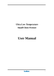
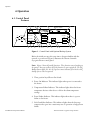
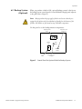
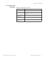
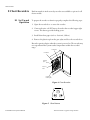
Cryogenic Storage
Freezers
Installation and Operation
325440H01 Rev. A December 2013
Visit us online to register your warranty
www.thermoscientific.com/labwarranty
IMPORTANT Read this instruction manual. Failure to follow the instructions in this manual can result in
damage to the unit, injury to operating personnel, and poor equipment performance.
CAUTION All internal adjustments and maintenance must be performed by qualified service personnel.
Material in this manual is for informational purposes only. The contents and the product it describes are
subject to change without notice. Thermo Fisher Scientific makes no representations or warranties with respect
to this manual. In no event shall Thermo be held liable for any damages, direct or incidental, arising from or
related to the use of this manual.
© 2013 Thermo Fisher Scientific Inc. All rights reserved.
Thermo Fisher Scientific Inc. provides this document to its customers with a product purchase to use in the
product operation. This document is copyright protected and any reproduction of the whole or any part of this
document is strictly prohibited, except with the written authorization of Thermo Fisher Scientific Inc.
The contents of this document are subject to change without notice. All technical information in this
document is for reference purposes only. System configurations and specifications in this document supersede
all previous information received by the purchaser.
Thermo Fisher Scientific Inc. makes no representations that this document is complete, accurate or errorfree and assumes no responsibility and will not be liable for any errors, omissions, damage or loss that might
result from any use of this document, even if the information in the document is followed properly.
This document is not part of any sales contract between Thermo Fisher Scientific Inc. and a purchaser. This
document shall in no way govern or modify any Terms and Conditions of Sale, which Terms and Conditions of
Sale shall govern all conflicting information between the two documents.
Table of Contents
Table of Contents
Cryogenic Models.....................................................................1
Safety Precautions.....................................................................2
General Recommendations .......................................................4
Temperature Monitoring .........................................................4
Recommended Use ..................................................................4
Unpacking ...............................................................................4
Operating Standards .................................................................5
Electrical Specifications ............................................................5
Installation ...............................................................................6
Location...................................................................................6
Wiring .....................................................................................6
Leveling ...................................................................................7
Operation .................................................................................8
Control Panel Features.............................................................8
Initial Loading .......................................................................10
Start Up .................................................................................11
Frame Heater Switch..............................................................14
Backup System (Optional) .....................................................15
Maintenance and Troubleshooting .........................................19
Condenser Maintenance ........................................................19
Gasket Maintenance...............................................................19
Defrosting the Freezer ............................................................20
Alarm Battery Maintenance....................................................20
Troubleshooting Procedures...................................................21
Chart Recorders......................................................................22
Set Up and Operation............................................................22
Power Supply .........................................................................23
Changing Chart Paper ...........................................................23
Calibration Adjustment..........................................................23
Warranty ................................................................................25
Cryogenic Models
1 Cryogenic Models
Thermo Scientific Cryopgenic Storage Freezers
The following cryogenic models are described in this manual:
Model Number
Suffix
ULT-10140-9-D
ULT-10140-9-M
ULT-10140-9-V
ULT-7150-9-D
ULT-7150-9-M
ULT-7150-9-V
19
24
23
19
24
23
Installation and Operation Manual
1
Safety Precautions
2 Safety Precautions
In this manual, the following symbols and conventions are used:
This symbol used alone indicates important operating instructions which
reduce the risk of injury or poor performance of the unit.
CAUTION: This symbol, in the context of a CAUTION, indicates a
potentially hazardous situation which if not avoided could result in minor to
moderate injury or damage to the equipment.
WARNING: This symbol indicates potentially hazardous situations which,
if not avoided, could result in serious injury or death.
WARNING: This symbol indicates situations where dangerous voltages
exist and potential for electrical shock is present.
The snowflake symbol indicates extreme low temperatures and high risk of
frostbite. Do not touch bare metal or samples with unprotected body parts.
This symbol indicates a need to use gloves during the indicated procedures.
If performing decontamination procedures, use chemically resistant gloves.
Use insulated gloves for handling samples and when using liquid nitrogen.
Before installing, using or maintaining this product, please be sure to read
this manual and product warning labels carefully. Failure to follow these
instructions may cause this product to malfunction, which could result in
injury or damage.
2 Installation and Operation Manual
Thermo Scientific Cryogenic Storage Freezers
Safety Precautions
Below are important safety precautions that apply to this product:
Use this product only in the way described in the product literature and in
this manual. Before using it, verify that this product is suitable for its
intended use. If this equipment is used in a manner not specified by the
manufacturer, the protection provided by the equipment may be impaired.
Do not modify system components, especially the controller. Use OEM
exact replacement equipment or parts. Before use, confirm that the product
has not been altered in any way.
WARNING: Your unit must be properly grounded in conformity with
national and local electrical codes. Never connect the unit to overloaded
power sources.
WARNING: Disconnect the unit from all power sources before cleaning,
troubleshooting, or performing other maintenance on the product or its
controls.
Thermo Scientific Cryopgenic Storage Freezers
Installation and Operation Manual
3
General Recommendations
3 General
Recommendations
3.1 Temperature
Monitoring
IMPORTANT NOTE We recommend the use of a redundant and independent
temperature monitoring system so that the freezer can be monitored continuously
for performance commensurate with the value of product stored.
3.2 Recommended Use
The refrigeration system is designed to maintain cryogenic temperatures
with safety only when the freezer is used for storage. These models may be
used in an ambient environment of 15-25°C (59-77°F).
This unit is not intended for use as a medical device.
CAUTION: This unit is not a “rapid-freeze” device. Freezing large
quantities of liquid, or high-water content items, will temporarily increase
the chamber temperature and will cause the compressors to operate for a
prolonged time period. This activity could also cause damage to the cabinet.
WARNING: DO NOT store flammable liquids in this unit.
Avoid opening the lid for extended time periods, since chamber temperature
air will escape rapidly. Room air, which is higher in humidity, replacing
chamber air may cause frost to develop in the chamber more rapidly.
3.3 Unpacking
At delivery, examine the exterior for physical damage while the carrier’s
representative is present. If exterior damage is present, carefully unpack
and inspect the unit and all accessories for damage.
If there is no exterior damage, unpack and inspect the equipment within
five days of delivery. If you find any damage, keep the packing materials
and immediately report the damage to the carrier. Do not return goods
without written authorization. When submitting a claim for shipping
damage, request that the carrier inspect the shipping container and
equipment.
CAUTION! Do not discard the sublids from chest-style units. The
sublids are necessary to maintain correct temperature, moisture control, and
economy of operation.
4 Installation and Operation Manual
Thermo Scientific Cryogenic Storage Freezers
Operating Standards
4 Operating
Standards
The freezers described in this manual are classified for use as stationary
equipment in a Pollution Degree 2 and Overvoltage Category II
environment.
These units are designed to operate under the following environmental
conditions:
4.1 Electrical
Specifications
•
Indoor use
•
Altitude up to 2000m
•
Maximum relative humidity 60% for temperatures
up to 32°C (90°F)
•
Main supply voltage fluctuations not to exceed 10% of the nominal
voltage.
The last character in the model number listed on the dataplate identifies the
electrical specifications for your unit.
The voltage types are D, M, and V, as specified in the following table:
Table 1: Electrical Specifications
Thermo Scientific Cryopgenic Storage Freezers
Model
Voltage
Frequency/
Phase
Amps/Breaker
10140D
208/230V
60Hz/1Ø
23.0/30A
10140M
380V
50Hz/3Ø
11.0/15A
10140V
230V
50Hz/1Ø
23.0/30A
7150D
208/230V
60Hz/1Ø
23.0/30A
7150M
380V
50Hz/3Ø
11.0/15A
7150V
230V
50Hz/1Ø
23.0/30A
Installation and Operation Manual
5
Installation
5 Installation
WARNING: Do not exceed the electrical ratings printed on the dataplate
located on the lower left side of the unit.
CAUTION! Improper operation of the equipment could result in
dangerous conditions. To preclude hazard and minimize risk, follow all
instructions and operate within the design limits noted on the dataplate.
5.1 Location
Install the unit in a level, well-ventilated indoor area free from vibration and
excessive dust.
To provide adequate ventilation, be sure to leave at least 12 inches of
clearance on the sides and behind the unit.
CAUTION! To allow for proper air flow, a minimum of 12 inches of
clearance space is required on the sides and behind the freezer. Allow enough
clearance so that the lid can swing open at least 90 degrees.
Do not position the equipment in direct sunlight or near heating diffusers,
radiators, or other sources of heat. The ambient temperature range at the
location must be 59 to 77°F (15 to 25°C).
Make sure that there is no other equipment discharging condenser outlet air
near the freezer’s condenser inlet.
5.2 Wiring
Always connect the freezer to a dedicated (separate) circuit. Supply voltage
must be within +10% or -10% of the freezer rated voltage.
CAUTION Connect the equipment to the correct power source. Incorrect
voltage can result in severe damage to the equipment.
CAUTION For personal safety and trouble-free operation, this unit must
be properly grounded before it is used. Failure to ground the equipment
may cause personal injury or damage to the equipment. Always conform to
the National Electrical Code and local codes. Do not connect the unit to
overloaded power lines.
CAUTION Do not position the unit in a way that impedes access to the
disconnecting device or circuit breaker in the back of the unit.
6 Installation and Operation Manual
Thermo Scientific Cryogenic Storage Freezers
Installation
WARNING: Never cut the grounding prong from the service cord plug. If
the prong is removed, the warranty is invalidated.
5.3 Leveling
The unit must be level both front to back and side to side.
To level chest models, leave the casters in place and shim the low wheel(s)
with strips of sheet metal cut at least 1/2 in. wider than the caster.
Thermo Scientific Cryopgenic Storage Freezers
Installation and Operation Manual
7
Operation
6 Operation
6.1 Control Panel
Features
2
6
11 12
13
20
21
22
BACKUP SYSTEM
SUPPLY
ON
check
fuse
cabinet
temperature
life-guard alert
off
power on
SUPPLY
EMPTY
extreme ambient alert
control
set point
power failure
alarm on
temperature failure
set point security
alarm test alarm reset
BATTERY
LOW
clean filter
warm alarm
set point
alarm
battery low
cold alarm
set point
voltageboost
16
17
1
23
7
8
3
4
5
9
10
14
15
19 18
Figure 1. Control Panel with Optional Backup System
Before the initial start up, take some time to become familiar with the
controls on your freezer. Figure 1 illustrates the Thermo Scientific
Cryogenic Freezer control panel.
Note: Figure 1 shows all possible functions. These functions vary depending on
the options. You may not have all of the functions on your equipment. The LN2
Backup System lights (21, 22, 23) represent status indicators for a built-in LN2
backup system, which is optional.
1. Three position keyed Power On Switch.
2. Power On Indicator. This indicator lights when power is connected to
the freezer.
3. Temperature Failure Indicator. This indicator lights when the freezer
temperature deviates either above or below the alarm temperature
settings.
4. Power Failure Indicator. This indicator lights when there is a power
failure to the freezer.
5. Life-Guard Alert Indicator. This indicator lights when the first stage
compressor has gone into a cautionary state of operation to help prevent
failure.
8 Installation and Operation Manual
Thermo Scientific Cryogenic Storage Freezers
Operation
6. Check Fuse Light. This indicator lights when the surge protector on the
main electronic panel is blown by a power surge.
7. Alarm Test Pad. Press this pad to start an alarm test (refer to Section
6.3.5).
8. Alarm Reset Pad. Press this pad to reset slowly blinking indicators.
Slowly blinking indicators denote that the condition has occurred but is
now within the given operating parameters. This pad is also depressed to
temporarily silence the audible alarm.
9. Cold Alarm Setpoint. Press this pad to set the cold alarm (refer to
Section 6.3.3).
10. Warm Alarm Setpoint. Press this pad to set the warm alarm (refer to
Section 6.3.3).
11. Control Setpoint. Press this pad to set the cabinet temperature (refer to
Section 6.3.2).
12. Cabinet Temperature Indicator. This indicator lights when the
temperature display window is showing the cabinet temperature.
13. Digital Temperature Display Window. This window displays chamber
temperature, alarm values, etc. depending on the operating status of the
freezer and the procedure being performed.
14. Decrement Pad (
15. Increment Pad (
). Use this pad to decrease temperature values.
). Use this pad to increase temperature values.
16. Extreme Ambient Alert. This indicator lights when the ambient
temperature has exceeded the upper limit of the recommended
operating range. If the Extreme Ambient Alert is activated, the ambient
environment needs to be improved for proper function of the freezer.
17. Clean Filter Indicator. This indicator lights when the air cooled
condenser or air filter is dirty.
18. Alarm Battery Low Indicator. This indicator lights when the charge on
the alarm battery is low. Press this button to display the percent of full
battery charge in the digital display window.
19. Voltage Boost Indicator. This indicator lights when incoming voltage is
low and the Voltage Safeguard has been activated. Press this pad to
display the current line voltage in the digital display window.
Thermo Scientific Cryopgenic Storage Freezers
Installation and Operation Manual
9
Operation
20. Alarm On/Set Point Security Indicator. This indicator lights when the
alarm is activated. It also indicates that Setpoint Security is activated.
The following indicators are available only when the freezer is equipped
with the optional backup system:
21. Backup System Supply On Indicator.
22. Backup System Empty Indicator
23. Backup System Battery Low Indicator.
6.2 Initial Loading
After reading and completing the Safety Considerations, Pre-Inst0allation,
Installation, and Operation sections of this manual, turn the Key Switch to
the POWER ON position and adjust the temperature setpoint if necessary,
following the instructions in Section 6.3 below.
The setpoint should be -140°C for ULT10140 models, -150°C for UL7150
models. Allow the freezer to operate at the desired temperature for a
minimum of 12 hours before loading.
CAUTION! Failure to follow these procedures or overloading the unit may
cause undue stress on the compressor or jeopardize user product safety.
10 Installation and Operation Manual
Thermo Scientific Cryogenic Storage Freezers
Operation
6.3 Start Up
6.3.1 Turning the Power On
Refer to Figure 1 as you complete the following procedures.
To start up your cryogenic freezer, complete the following steps:
1. Connect the freezer to the power source.
2. Turn the key switch to the POWER ON position. The Power On LED
and the Cabinet Temperature LED illuminate.
Note: The alarm function is not active at this time. Refer to 6.3.3 for
information about setting the alarms. In addition, the Setpoint Security will be
deactivated in this key position.
3. The unit will start about 30 seconds later.
6.3.2 Setting the Cabinet
Temperature
To set the cabinet temperature, complete the following steps:
1. Press and hold the Control Setpoint pad.
2. The Control setpoint LED lights and the Cabinet Temperature LED
goes out.
3. Press and hold to increase the temperature or to decrease the
temperature. The digital display scrolls through temperature settings.
Required setpoint is -140°C for 10140 models, -150°C for 7150
models.
4. Release both pads when the digital temperature display window shows
the correct setpoint value.
Note: If no keys are pressed within ten seconds, the temperature display reverts
to the cabinet temperature.
Thermo Scientific Cryopgenic Storage Freezers
Installation and Operation Manual
11
Operation
6.3.3 Setting the Alarms
To set the cold alarm, complete the following steps:
1. Confirm that the key switch is at the Power On position (Setpoint
Security disabled)
2. Press and hold the Cold Alarm Setpoint pad. The LED next to this pad
lights. The temperature display shows the Cold Alarm value.
3. Press and hold or to adjust the Cold Alarm Setpoint. This setpoint
should be at least 10°C colder than the operating setpoint.
4. Release both pads when the digital temperature display window shows
the correct setpoint value.
To set the warm alarm, complete the following steps:
1. Confirm that the key switch is at the Power On position (Setpoint
Security disabled).
2. Press and hold the Warm Alarm Setpoint pad. The LED next to this pad
lights. The temperature display shows the Warm Alarm value.
3. Press and hold or to adjust the Warm Alarm Setpoint. This
setpoint should be at least 10°C warmer than the operating setpoint.
4. Release both pads when the digital temperature display window shows
the correct setpoint value.
When the cabinet temperature drops below the Warm Alarm setting, turn
the key switch to ALARM ON. The freezer is ready to operate.
Note: If a power failure lasting over 30 seconds occurs, the POWER ON light
goes out and the POWER FAILURE light and digital temperature display flash
simultaneously.Y
IMPORTANT NOTE: You must turn the three-position key switch to the
ALARM ON/SETPOINT SECURITY position to activate the alarm and
place it in security operation. Do not perform this action until the cabinet
temperature drops below the warm alarm setpoint.
12 Installation and Operation Manual
Thermo Scientific Cryogenic Storage Freezers
Operation
6.3.4 Alarm Reset & Status
Lights
The alarm reset feature ensures user acknowledgment of the occurrence of
certain alarm conditions. This provides greater monitoring power by
alerting the user if an alarm condition has occurred during periods when the
freezer must be left unattended. The alarm conditions incorporating this
feature are:
•
Temperature Failure-Warm Alarm
•
Temperature Failure-Cold Alarm
•
Voltage Low
•
Power Failure
•
Life-Guard Alert
•
Extreme Ambient Alert
During any of these alarm conditions, the corresponding indicator will flash
quickly, approximately 90 times per minute. If the alarm condition then
disappears, the flash rate will decrease to approximately 15 times per
minute. The indicator will then remain flashing at this rate, unless the
condition reoccurs, until the Alarm Reset button is pressed. Once this has
occurred, the indicator will no longer be lit.
In the case of TEMPERATURE FAILURE-WARM ALARM and
TEMPERATURE FAILURE-COLD ALARM, if these conditions have
occurred but are now within the given limits, the two indicators will
alternately flash (180° out of phase). In addition, for these two temperatures
failures, the highest temperature and lowest temperature, respectively,
during the error condition will be saved. Prior to the temperature failure
being reset, the temperature extreme may be viewed by pressing the Cabinet
Temperature pad in conjunction with either the Warm Alarm Setpoint pad
or the Cold Alarm Setpoint pad.
Note: Once the Alarm Reset button is depressed, the excursion temperature
value is reset to the current cabinet temperature.
Thermo Scientific Cryopgenic Storage Freezers
Installation and Operation Manual
13
Operation
6.3.5 Alarm Test
To test the warm alarm, complete the following steps:
1. Press and hold the Alarm Test pad. The digital temperature display
indicates rising temperature. When the temperature reaches the warm
alarm value, the alarm sounds.
Note: The temperature of the refrigerated space does not change during this
procedure. Only the sensor is heated.
2. Release the Alarm Test pad, the sensor and display return to cabinet
temperature in a few minutes.
You can press the Audio Silence pad to silence the alarm but the alarm will
ring back in five to seven minutes. You can silence the alarm in this manner
as many times as necessary until the sensor cools below the warm alarm
temperature. The alarm quits automatically when the sensor cools below the
warm alarm value.
Note: There is a limit on the alarm test feature. The alarm test will not
commence if the warm alarm setpoint is more than 15 degrees warmer than the
operating temperature setpoint.
6.4 Frame Heater
Switch
Cryogenic chest freezers (-140° and -150°C) have a frame heater switch
which can be used to prevent or remove condensation near the freezer
compartment lid. The switch is located in back of the unit near the top
center, to the right of the junction box. Turning the switch to the up
position heats up the frame around the lid.
Heating the frame has no effect on interior cabinet temperature. You can
turn on the switch whenever there is condensation near the lid.
14 Installation and Operation Manual
Thermo Scientific Cryogenic Storage Freezers
Operation
6.5 Backup System
(Optional)
When you purchase a built-in LN2 optional backup system for the freezer,
the backup system control panel is located behind a hinged panel adjacent
to the grill (refer to Figure 3).
Note: Always purchase 22 psig supply cylinders and ensure that they are
equipped with siphon tubes for withdrawing liquid from the bottom of the
cylinder. LN2 bottles are functional at any reasonable temperature.
Use this panel to set the backup initiation temperature:
Digital Temperature
Display
Temperature Control
Setpoint Screw
TEMPERATURE °C
POWER
OFF
PUSH
TO SET
ON
Power
Switch
SETPOINT
ADJUST
Temperature Control
Set Button
Figure 2. Control Panel for Optional Built-In Backup System
Thermo Scientific Cryopgenic Storage Freezers
Installation and Operation Manual
15
Operation
6.4.1 LN2 Precautions
The following are precautions for using liquid LN2 backup systems.
WARNING! Transport the cylinders in a hand truck or cart with secure
chain ties for the cylinder. After cylinders are connected to the equipment,
securely attach them with chains to a solid, stationary object such as a
building column.
WARNING! LN2 liquid is non-poisonous but it is very cold and will burn
unprotected skin. Always wear protective eyewear and clothing when
changing cylinders or working on the piping systems attached to an active
source of liquid refrigerant.
WARNING! The gases produced by evaporation of LN2 are
non-poisonous but displace the oxygen in a confined space and can cause
asphyxiation. Do not store the cylinders in subsurface or enclosed areas.
CAUTION! When closing the cylinder valve, make sure that the
injection solenoid is energized to allow all the liquid to bleed off instead of
being trapped in the supply tubing. Failure to do this results in activation of
the pressure relief device, which could damage the freezer and requires
replacing if it is activated.
CAUTION! The flow of liquid LN2 will be discontinued if the lid is
opened during operation of the backup system. For units operated with
free-standing, field installed type backup system, the flow of liquid LN2 will
be discontinued upon lid opening only if the switch provided with the
free-standing package is installed on the freezer.
6.4.2 Installation
Field installed systems are supplied with complete installation and operating
instructions. If your system is factory installed, the freezer is shipped with a
coiled length of tubing to connect the freezer to the bottles:
•
5/8 in. OD copper tubing covered with Armaflex™ insulating tubing for
connection to the LN2 supply.
Straighten the coiled tubing and connect one end to the labeled connection
on the freezer and the other end to the supply bottle or building supply
fitting.
16 Installation and Operation Manual
Thermo Scientific Cryogenic Storage Freezers
Operation
6.4.3 Operation
To activate the optional backup system, complete the following steps:
1. Push the Power Switch to the ON position. The digital temperature
display window shows the current cabinet temperature.
2. Press and hold the Push to Set button to display the setpoint
temperature in the digital temperature display window.
3. Use a small screwdriver to rotate the Setpoint Adjust screw until the
correct backup operating temperature shows in the display window. The
backup system setpoint should be at least 5°C warmer than the warm
alarm setpoint. For example, if your control setpoint is 150°C and your
warm alarm setpoint is 140°C, the backup system setpoint should be no
colder than 135°C.
Note: The temperature shown in the display window is accurate to ±1°C.
The backup system can run for a minimum of eight hours on a fully charged
battery.
Note: You must push the Power Switch to the ON position in order to activate
the backup system.
6.4.4 System Status Lights
In addition to the backup control system, the built-in backup system
includes main control panel system status lights. These lights are only
available when the backup system is installed.
•
The Supply On Indicator lights when the backup system is operating on
battery power.
•
The Backup System Battery Low Indicator lights when the backup
system battery charge is low. The built-in battery charger recharges the
battery to full charge when power is restored to the system.
Note: Since rechargeable batteries degrade over time, the battery should be
replaced after approximately one or two years.
Thermo Scientific Cryopgenic Storage Freezers
Installation and Operation Manual
17
Operation
•
The Backup System Empty Indicator lights when the standby LN2
bottle is empty.
LN2 Inlet Conn.
Copper Tubing
Factory Supplied
0.625" O.D.
2.375"
24.75"
MACHINE COMPARTMENT
REAR VIEW
Figure 3. Location of LN2 Connection Site
Table 1-1. Backup System Flow Rates – Cryogenic Freezers
Lbs/hr @ 75×F Ambient Temperature (Flow Rate)
Center Air Temperature
-150×C
-140×C
-130×C
-120×C
Empty
11.3
10.0
9.0
8.0
1/2 Full
9.7
8.6
7.6
6.8
Full
7.8
6.8
6.0
5.2
Empty
15.2
13.5
11.9
10.3
1/2 Full
12.0
10.4
9.4
8.3
Full
8.9
7.8
7.0
6.1
Liquid LN2
Chest Freezers
7 ft3
10 ft3
18 Installation and Operation Manual
Thermo Scientific Cryogenic Storage Freezers
Maintenance and Troubleshooting
7 Maintenance and
Troubleshooting
WARNING! Unauthorized repair of your freezer will invalidate your
warranty. Contact Technical Service at 1-800-438-4851 for additional
7information.
CAUTION! Maintenance should only be performed by trained
personnel.
7.1 Condenser
Maintenance
7.1.1 Cleaning the Condenser
and Filter
Clean the condenser at least every six months; more often if the laboratory
area is extremely dust prone.
To clean the condenser, complete the following steps:
1. Pull the grill open.
2. Remove the filter. Check the fans. If a fan is not operating, contact an
Authorized Service Company immediately.
3. Vacuum the condenser, using a soft brush attachment to avoid
damaging the fins.
4. Remove the filter.
5. Vacuum the filter to remove loose dust, rinse the filter in clean water,
shake the excess water from the filter, and reinstall the filter.
6. Close the grill.
7.2 Gasket Maintenance
Periodically check the gaskets around the lid for punctures or tears. Leaks
are indicated by a streak of frost which forms at the point of gasket failure.
Make sure that the cabinet is level (refer to Section 5.3 on page 7 for leveling
information).
Keep the lid gasket clean and frost free by wiping gently with a soft cloth or
soft brush.
Thermo Scientific Cryopgenic Storage Freezers
Installation and Operation Manual
19
Maintenance and Troubleshooting
7.3 Defrosting the
Freezer
Defrost the freezer once a year or whenever the ice buildup exceeds 1/4”.
To defrost, complete the following steps:
1. Remove all products and place in another freezer.
2. Turn off the freezer.
3. Open the outer lid and sub-lids.
4. Let the freezer stand with the lids open for at least 24 hours. This allows
both the interior and foamed refrigerant system to warm to room
temperature.
5. Dispose of the ice and wipe out any water standing in the bottom of the
cabinet.
6. If there is freezer odor, wash the interior with a solution of baking soda
and warm water. Clean the exterior with any common household
cleaner.
7. Reinstall the sub-lids, close the lid, restart the freezer and reload.
7.4 Alarm Battery
Maintenance
Have a technician check the condition of the alarm battery at least once a
year.
To replace the alarm battery, complete the following steps:
1. Remove the front grill. The alarm battery is located directly behind the
grill. The terminals are the “push on” type.
2. Grasp the terminal with pliers and work it gently back and forth while
pulling it off. The fittings are tight.
3. Remove the battery and put the new battery in place.
Note: You may have to cut a strip of silicone rubber in order to remove the
battery.
4. Connect the battery terminals and replace the front grill.
20 Installation and Operation Manual
Thermo Scientific Cryogenic Storage Freezers
Maintenance and Troubleshooting
7.5 Troubleshooting
Procedures
Table 1-2. Troubleshooting Procedures
Problem
Thermo Scientific Cryopgenic Storage Freezers
Details
Check Fuse indicator is
on.
Surge protector is blown. .
Clean Filter indicator is
on.
Condenser filter is dirty. Refer to Section 7.1 on
page 19.
Alarm Battery Low
indicator is on.
Alarm battery is low on charge .
Voltage Boost indicator
is on.
Low incoming line voltage to the freezer..
No display, no fans
running.
No power to the unit.
Installation and Operation Manual
21
Chart Recorders
8 Chart Recorders
Panel-mounted six-inch seven-day recorders are available as options for all
freezer models.
8.1 Set Up and
Operation
To prepare the recorder to function properly, complete the following steps:
1. Open the recorder door to access the recorder.
2. Connect the nine volt DC battery located at the recorder’s upper right
corner. This battery provides backup power.
3. Install clean chart paper (refer to Section 8.3 below).
4. Remove the plastic cap from the pen stylus and close the recorder door.
Recorder operation begins when the system is powered on.The recorder may
not respond until the system reaches temperatures within the recorder’s
range.
9 Volt Battery
Chart Buttons
Imprinting
Stylus
Reference
Mark
Hub-Nut and
Retaining Wire
Chart
Figure 4. Chart Recorder
CHANGE CHART
3
1
2
Figure 5. Chart Buttons
22 Installation and Operation Manual
Thermo Scientific Cryogenic Storage Freezers
Chart Recorders
8.2 Power Supply
The recorder normally uses AC power when the system is operating. If AC
power fails, the LED indicator flashes to alert you to a power failure. The
recorder continues sensing cabinet temperature and the chart continues
turning for approximately 24 hours with back-up power provided by the
nine-volt battery.
The LED indicator glows continuously when main power is functioning
and the battery is charged.
When the battery is low, the LED flashes to indicate that the battery needs
to be changed.
8.3 Changing Chart
Paper
To change the chart paper, complete the following steps:
1. Locate the pressure sensitive buttons at the front, upper left of the
recorder panel.
2. Press and hold the Change Chart button (#3 in Figure 6) for one
second. The pen will move off the scale.
3. Unscrew the center nut, remove the old chart paper, and install new
chart paper. Carefully align the day and time with the reference mark (a
small groove on the left side of the recorder panel).
4. Replace the center nut and hand tighten. Press the Change Chart button
again to resume temperature recording.
8.4 Calibration
Adjustment
This recorder has been accurately calibrated at the factory and retains
calibration even during power interruptions. If required, however,
adjustments can be made as follows:
1. Run the unit continuously at the control setpoint temperature.
Continue steady operation for at least two hours to provide adequate
time for recorder response.
2. Measure cabinet center temperature with a calibrated temperature
monitor.
3. Compare the recorder temperature to the measured cabinet
temperature. If necessary, adjust recorder by pressing the left (#1 in
Figure 6) and right (#2) chart buttons.
Thermo Scientific Cryopgenic Storage Freezers
Installation and Operation Manual
23
Chart Recorders
Note: The stylus does not begin to move until the button is held for five
seconds.
If you find that the recorder frequently needs to be calibrated after paper
changes, the program may have changed. To confirm that the program is
correct:
1. Press button #3 in Figure 6 and allow the pin to move off the scale.
2. Press #1 for 10 seconds and release.
3. Confirm that the green LED flashes 3 times followed by a pause. If the
number of blinks is greater than or less than 3, adjust the number using
the left (#1 in Figure 6) and right (#2) chart buttons.
4. When the green LED blinks 3 times to confirm the resetting, press the
#3 button. The pin arm should then return to indicate the current
temperature. Repeat Steps 1-3 if necessary.
24 Installation and Operation Manual
Thermo Scientific Cryogenic Storage Freezers
Warranty
9 Warranty
Be sure to register your warranty online:
www.thermoscientific.com/labwarranty
THERMO FISHER SCIENTIFIC USA FREEZER WARRANTY
The Warranty Period starts two weeks from the date your equipment is
shipped from our facility. This allows for shipping time so the warranty will
go into effect at approximately the same time your equipment is delivered.
The warranty protection extends to any subsequent owner during the
warranty period.
During the first two years of the warranty period, component parts proven
to be non-conforming in materials or workmanship will be repaired or
replaced at Thermo's expense, labor included. The ULT Freezers include an
additional three year warranty on the compressors, parts only, F.O.B.
factory. Installation and calibration is not covered by this warranty
agreement. The Technical Services Department must be contacted for
warranty determination and direction prior to any work being performed.
Expendable items, i.e., glass, filters, pilot lights, light bulbs and door gaskets
are excluded from this warranty.
Replacement or repair of component parts or equipment under this
warranty shall not extend the warranty to either the equipment or to the
component part beyond the original two year warranty period. The
Technical Services Department must give prior approval for the return of
any components or equipment.
THIS WARRANTY IS EXCLUSIVE AND IN LIEU OF ALL OTHER
WARRANTIES, WHETHER WRITTEN, ORAL, OR IMPLIED. NO
WARRANTIES OF MERCHANTABILITY OR FITNESS FOR A
PARTICULAR PURPOSE SHALL APPLY. Thermo shall not be liable for
any indirect or consequential damages including, without limitation,
damages relating to lost profits or loss of products.
Your local Thermo Scientific Sales Office is ready to help with
comprehensive site preparation information before your equipment arrives.
Printed instruction manuals carefully detail equipment installation,
operation, and preventive maintenance.
If equipment service is required, please call your Technical Services
Department at 1-800-438-4851 (USA and Canada). We're ready to answer
your questions on equipment warranty, operation, maintenance, service,
and special applications. Outside the USA, contact your local Thermo
Scientific office or distributor for warranty information.
Thermo Scientific Cryopgenic Storage Freezers
Installation and Operation Manual
25
Warranty
THERMO FISHER SCIENTIFIC FREEZER INTERNATIONAL
WARRANTY
The Warranty Period starts two months from the date your equipment is
shipped from our facility. This allows for shipping time so the warranty will
go into effect at approximately the same time your equipment is delivered.
The warranty protection extends to any subsequent owner during the
warranty period. Dealers who stock our equipment are allowed an
additional four months for delivery and installation, providing the warranty
card is completed and returned to the Technical Services Department.
During the first two years of the warranty period, component parts proven
to be non-conforming in materials or workmanship will be repaired or
replaced at Thermo's expense, labor excluded. The ULT Freezers include an
additional three year warranty on the compressors, parts only, F.O.B.
factory. Installation and calibration is not covered by this warranty
agreement. The Technical Services Department must be contacted for
warranty determination and direction prior to any work being performed.
Expendable items, i.e., glass, filters, pilot lights, light bulbs and door gaskets
are excluded from this warranty.
Replacement or repair of component parts or equipment under this
warranty shall not extend the warranty to either the equipment or to the
component part beyond the original two year warranty period. The
Technical Services Department must give prior approval for the return of
any components or equipment.
THIS WARRANTY IS EXCLUSIVE AND IN LIEU OF ALL OTHER
WARRANTIES, WHETHER WRITTEN, ORAL, OR IMPLIED. NO
WARRANTIES OF MERCHANTABILITY OR FITNESS FOR A
PARTICULAR PURPOSE SHALL APPLY. Thermo shall not be liable for
any indirect or consequential damages including, without limitation,
damages relating to lost profits or loss of products.
Your local Thermo Scientific Sales Office is ready to help with
comprehensive site preparation information before your equipment arrives.
Printed instruction manuals carefully detail equipment installation,
operation, and preventive maintenance.
If equipment service is required, please contact your local Thermo Scientific
office or local distributor.
We're ready to answer your questions on equipment warranty, operation,
maintenance, service, and special applications. Outside the USA, contact
your local Thermo Scientific office or distributor for warranty information.
26 Installation and Operation Manual
Thermo Scientific Cryogenic Storage Freezers
Important
For your future reference and when contacting the factory, please have the
following information readily available:
Model Number:
Serial Number:
Date Purchased:
The above information can be found on the dataplate attached to the
equipment. If available, please provide the date purchased, the source of
purchase (manufacturer or specific agent/rep organization), and purchase
order number.
IF YOU NEED ASSISTANCE:
SALES DIVISION
Phone:
1-866-984-3766 (866-9-THERMO)
LABORATORY PARTS and SERVICE
Phone:
1-800-438-4851
TECHNICAL SUPPORT
Phone:
1-800-438-4851
Thermo Fisher Scientific Inc.
275 Aiken Road
Asheville, NC 28804
United States
www.thermofisher.com
3)3FW"


![Cryogenic Freezer - User Manual [DE]](http://vs1.manualzilla.com/store/data/006770261_1-b473ed264828375d621c152dd742b342-150x150.png)