1
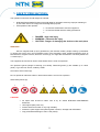
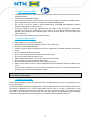
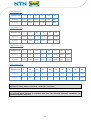
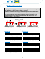
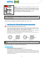
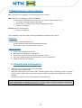
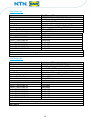
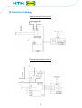
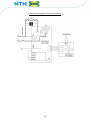
INDUCTION HEATERS
Read these operation
instructions attentively
INSTRUCTION MANUAL
Fast Therm 20
Fast Therm 35
Fast Therm 150
Fast Therm 300
NTN-SNR ROULEMENTS
1 rue des Usines – BP 2017
74000 Annecy Cedex - France
www.ntn-snr.com
Control all parts without delay for possible transport
damages. If such damages are determined inform the
carriers immediately
TABLE OF CONTENTS
1. Safety precautions .............................................................. 2
2. Introduction .......................................................................... 5
3. Installation ............................................................................ 5
4. Setting up the work piece ................................................... 6
5. Fast therm 20 operating instructions ................................ 7
6. Fast Therm 35, 150 and 300 operating instructions ........ 8
7. Malfunctioning / Error Signals ......................................... 10
8. Cleaning and maintenance ............................................... 10
9. Technical data .................................................................... 11
10. Electrical Drawing ........................................................... 13
11. Declaration of conformity .............................................. 15
1
1. SAFETY PRECAUTIONS:
The operation instruction should always be followed:
•
•
NTN-SNR ROULEMENTS shall not be held liable for damages caused by improper handling or
by use which does not comply with the designation purpose.
Prerequisites of the operator:
He must be authorised to use this equipment
He must be familiar with the safety precautions
DANGER : High risk injury
WARNING : Potential risk injury
CAUTION : Danger of damaging the device or the work piece
WARNING! :
Since a magnetic field (4+5) is generated by the induction heater, people wearing a pacemaker
(1) should not work or be in the immediate vicinity of the apparatus. Other sensitive equipment such as
wrist watches, magnetic carriers, electronic circuits (3), etc. might also be affected. The safety distance is
1.5 meters (57”).
The equipment should not be used in areas where there is a risk for explosion.
Use protective gloves (danger of burning your hands). Delivered gloved (7) are suitable up to 150°C
(302°F). Type Oil Tuff, 52-647, made by Ansell.
Hot surface avoid contact (6)
Do not operate an Induction heater in areas where there is a risk of an explosion.
Wear Safety Shoes (8)
1
2
3
4
5
6
7
8
CAUTION:
•
•
•
•
•
All repair work should be taken care of by an official NTN-SNR ROULEMENTS
distributor.
Use original spare parts only.
Protect heater from water or very high humidity.
Protect the yoke support and yokes against corrosion, damage and deformation.
Only preheat ball bearings to max 110°C (230°F).
2
1.1 SAFETY INSTRUCTIONS :
•
•
•
•
•
•
The user should have an appreciation of the contents of this manual, and be familiar with safe
workshop practice
Follow the User Manual at all times.
Ensure that the machine operates at the correct supply voltage. The heater is supplied with a
plug, change the plug should only be made by a suitably qualified person.
Do not use or store the heater in humid environments. NTN-SNR ROULEMENTS induction
heaters are designed for indoor use only.
Use proper handling equipment, appropriate for the weight of the work piece or yoke. Never
support the pieces to be heated with a metal cable or have anything metallic hanging in the
proximity of the magnetic field. Extremely high currents can flow through the cable, causing the
cable to heat up.
Do not hold metal objects near the yokes and poles
1.2. SAFETY PRECAUTIONS:
•
•
•
•
•
•
•
•
•
•
•
•
Place heater only on a horizontal surface.
Keep distance to surrounding object by minimum of 1 meter (38”)
Use only in well ventilated location.
Prevent to heat up object containing Oil, grease or similar due to possible generator of fumes and
smoke.
Do not inhale/breath fumes or smoke
Do not move or lift heater after heating process when warm
Do not rout supply cable through the core.
While heating keep at least 1 meter (38”) distance from the heater.
Never remove the yokes during the heating cycle.
Do not modify the heater and do not use self-fabricated yokes.
Always check that the yoke is correctly adjusted to the poles otherwise excessive vibration may
occur.
Only switch the machine on when the yoke is positioned correctly- on models equipped with a
pivoting yoke, the yoke should always be closed.
NOTE: Since our products are subject to continuous improvement, we reserve the right to change
the content of this document.
1.3. SAFETY FEATURES:
When using temperature mode, the heater will switch off automatically if the rate of temperature rise is
too low (E 02/E 03).
An induction heater works due a magnetic field. In figures below there are some measured values of the
flux density in MilliTesla (mT). These measurements can be used as a guide in conforming to local
regulations regarding the maximum time exposure of people to magnetic fields. The values below are
only valid for a combination of bearing type and yoke bar. Different configurations may give different
values due to the large variety of bearing types in combination with the different yoke bars.
3
Fast Therm 20:
Distance cm
0
10
20
30
40
50
X (mT)
2.95
0.76
0.21
0.11
0.09
0.07
Y (mT)
3.74
0.84
0.32
0.16
0.11
0.09
0
10
20
30
40
50
X (mT)
4.26
1.12
0.35
0.16
0.11
0.08
Y (mT)
3.58
1.66
0.56
0.27
0.16
0.09
0
10
20
30
40
50
60
70
X (mT)
13.5
3.4
1.5
0.6
0.3
0.19
0.09
0.08
Y (mT)
3.58
1.66
0.56
0.27
0.16
0.09
0.1
0.09
0
10
20
30
40
50
60
70
80
90
X (mT)
2.4
1.9
0.69
0.4
0.3
0.23
0.16
0.15
0.09
0.08
Y (mT)
1.77
1.13
0.69
0.4
0.3
0.23
0.16
0.15
0.13
0.09
Fast Therm 35:
Distance cm
Fast Therm 150:
Distance cm
Fast Therm 300:
Distance cm
WARNING!
We advise a safety distance of at least 1 meter (38”) for people.
CAUTION!
The machine works through an induction field. This can influence electronic equipment, e.g.
watches, magnetic charts etc.
4
2. Introduction:
The NTN-SNR ROULEMENTS induction heaters are intended for heating rolling bearings. Other metal
components forming a closed circuit such as bushings, shrink rings, pulleys and gears can also be
heated. This will facilitate mounting where an interference fit is required.
The heaters are designed to heat the work piece up to a maximum temperature of 240ºC (464°F).
NTN-SNR ROULEMENTS heaters can be used on continuous bases.
By heating with the time function this has to be checked with an external temperature meter. Always
place the temperature sensor to check while the first heating.
CAUTION:
Bearings should be heated up on most of the cases to a maximum temperature of 120ºc (248ºf).
Do not use induction heaters for bearings or work pieces, which are outside the minimum or
maximum dimensions specified in this manual.
Do not switch off the heater with the main switch while heating cycle is running.
Operation condition:
The heater is designed to be used in an industrial environment with an ambient temperature of 0°C to
40°C (32°F to 104°F) and an atmospheric humidity of 5% to 90%. The induction heater is meant for
indoor use only.
3. Installation:
•
•
•
•
•
•
•
•
•
•
Remove packing material and place the induction heater on a non-ferrous, stable, flat
surface. The box will normally contain the heater, a yoke or a set of yokes, the temperature
probe and a pair of heat-resistant gloves.
Check that the supply voltage and current meet the specifications on the plate that is located
on the back of the machine.
As there are a large number of plug types, change the NTN-SNR ROULEMENTS induction
heaters’ plug provided with a plug that fits to your power supply.
The wires should be connected as follows:
o Fast Therm 20 ET 35: Braun (Black us) = Phase | blue (White us) = neutral | Green /
yellow = ground.
o Fast Therm 150 et 300: Phase = blue (black us) | Phase = Brown (black us) | Ground
= Green / yellow:
Make sure that the supply cable cannot come into contact with the bearing that is to be
heated. Insert the plug into a shockproof wall socket.
Connect heater to electric mains,
Keep distance to surrounding object by 0.5meter ( 19”)
Turn main switch from 0 to 1
The heater will emit a short beep and in the display 110°C (230F) will appear.
The induction heater is now ready to be used.
5
4. Setting up the work piece:
WARNING!
Use appropriate hoisting equipment for heavy components and yokes. The manual lifting of heavy
pieces is a common cause of injury.
Wear Safety Shoes as inductor yokes can slip out of your hands.
The weight of the work-piece should not exceed the maximum weight shown in drawing below.
Exceeding these limits may result in equipment failure leading to personal injuries.
Ensure that the mains cable cannot come into contact with the work piece. Damage to the cable
may result in electrocution.
Never support components with a metal cable or have any hanging in the proximity of the
magnetic field. Extremely high currents can flow through the cable causing a quick raise of
temperature, resulting in a risk of burning
The work piece can be set up in two different ways:
D
Vertical
•
•
Horizontal
Vertically and Horizontally: The part should never touch the housing.
Small objects to be heated in vertically position
Fast Therm 20:
Fast Therm 35:
Max. dimensions part
Max inner diameter (d): 160 mm (6.3”)
Min inner diameter (d): 15* mm (0.6”)
Max outer diameter (D): 280 mm (11”)
Min outer diameter (D): NA
Max height (C): 120 mm (4.72”)
Min weight part : no
Max weight part (bearing): 40 kg (88lbs)
Max weight part (solid): 20 kg (44lbs)
Max dimensions part
Max inner diameter: 190 mm (7.48‘‘)
Min inner diameter: 15 mm (0.6‘‘)
Max outer diameter: 410 mm (16.14‘‘)
Min outer diameter : NA
Max height: 180 mm (7.09’’)
Min weight part : no
Max weight part (Bearing): 70 kg (154 lbs)
Max weight part (solid) : 40 kg ( 88 lbs)
Fast Therm 150:
Fast Therm 300:
Max dimensions part:
Max inner diameter: 190 mm (7.48‘‘)
Min inner diameter: 20** mm (0.8‘‘)
Max outer diameter: 490 mm (19.29‘‘)
Min outer diameter : NA
Max height: 210 mm (8.57’’)
Min weight part: 5 kg (11 lbs)
Max weight part (Bearing): 150 kg (330.7 lbs)
Max Weight part (solid) : 150 kg (330.7 lbs)
Max dimensions part:
Max inner diameter: 600 mm (23.62‘‘)
Min inner diameter: 30 mm (1.18“)
Max outer diameter: 740 mm (29.13‘‘)
Min outer diameter: NA
Max height: 330mm (13’’)
Min weight part: 5 kg (11 lbs)
Max weight part (Bearing): 300KG (661.4 lbs)
Max Weight part (solid) : 300KG (661.4 lbs)
* : With special yoke 10x10x200
** : With special yoke 14x14x350
6
•
Parts heavier have to be heated horizontally
•
Maximum weight part for the pivoting yoke:
Fast therm 35
Fast Therm 150
Fast Therm 300
Max weight (F)
Max weight (F)
Max weight (F)
8KG (17 lbs)
12KG (26 lbs)
20KG (44 lbs)
5. Fast Therm 20 operating instructions:
Do not start the heating process without using a bar!
• Connect the machine (according to the type in 110 or 230V-16A) and attach the magnetic sensor.
Set the contactor to position « I ».
The display reads 110°C (230°F).
• Choose the most suitable yoke for the bearing to be heated. The yoke
•
should fill the bearing bore as completely as possible (sketch N°3). Slide the bearing over the
bar.
Heating can take place in temperature mode.
Place the magnetic sensor on the inner ring. (sketch n°4)
Sketch n°3
Sketch n°4
USEFUL TIP: apply some grease or Vaseline to the bar cross-section, this will help avoid
vibrations.
7
When the equipment is running, the default display on the screen is 110°C
(230°F).
By pressing keys A and B, you can raise or drop the temperature. Press the
key C « START/STOP » to begin heating. The screen begins to show the
temperature from 50°C (122°F). Once the required te mperature is reached,
an audible signal is heard and the screen flashes.
Press « START/STOP » to stop the signal. Remove the part.
Note: heating restarts as soon as the temperature drops by 5°c (41°f). It will do this 5 times in a
row, then which an audible signal is heard. Press the « start/stop » key to stop it and remove the
sensor. Remove the part.
HEATING CAN BE STOPPED AT ANY TIME BY PRESSING THE « STOP » KEY.
6. Fast Therm 35, 150 and 300 operating instructions
Do not start the heating process without using a yoke
1- Connect the equipment (according to the type in 110-15A or 230V-16A for THERM 20 and 35
and according to the type in 400 or 460V-63A for THERM 150 and 300) and attach the magnetic
sensor. Set the contactor to Position « I ». The display reads 110°C (230°F).
2- Choose the most suitable pivoting arm for the bearing to be heated. The yoke must fill the
bearing bore as much as possible (sketch #3). Slide the bearing over the yoke.
3- Put magnetic probe on work piece close to the bore. Make sure that the place reserved for the
probe is free of any grease or oil (sketch #4).
USEFUL TIP: apply some grease or Vaseline to the bar cross-section, this will help avoid
vibrations.
Heating can then take place in either time or temperature mode
6.1. Temperature mode:
•
•
•
•
Place the magnetic sensor on the inner ring (sketch n°4).
Select temperature mode by pressing key D.
Once the machine is running the screen will display 110°C (230°F) by default.
You can press keys A and B to raise or drop the temperature. Press the « START/STOP » key to
begin heating. The screen will show the temperature as from 50°C (122°F). Once the desired
temperature is reached, a signal is heard and the screen flashes. Press « START/STOP » to stop
the signal. Remove the part.
8
6.2. Time mode:
•
•
•
•
•
•
Switch on the equipment. Press key E.
The machine displays « 00.00 ».
Set the heating time in seconds by pressing keys A and B. After setting the seconds, adjust the
time in minutes by pressing key E and then use keys A and B.
Select the desired time (max 99.59 min) and press the « START/STOP » key to begin heating.
The count-down will then begin on the time display.
During heating, the temperature can be displayed by pressing key F. The magnetic sensor
must then be in place. (Sketch n°4)
Once heating is over, the signal is heard. Press the « START/STOP » key to stop it. Remove the
part
NOTE: Heating restarts as soon as the temperature drops by 5°C (41°F). It will do this 5 times in a
row, and then an audible signal is heard. Press the « START/STOP » key to stop it and remove the
sensor. Remove the part.
HEATING CAN BE STOPPED AT ANY TIME BY PRESSING THE « STOP » KEY.
-
-
Always use magnetic temperature probe (hereafter referred to as the “probe”) for heating in the
temperature mode.
The probe is suitable for operation up to a maximum temperature of 240°C (464°F)
As a safety feature, the connection between magnet and probe will break above the maximum
temperature. If this occurs when operating in the temperature mode, the machine will turn itself
off since the probe will fail to register any increase in the temperature over a set of period of time.
A probe fixed to a clamp is also available when heating non-magnetic work pieces:
o Ensure that the area where the probe is located is completely clean.
o Connect the probe by inserting the plug into the socket at the side of the heater, watch
out for + - !
CAUTION:
Treat the probe with care. It is a valuable part of the heater and can easily be broken through
careless handling. After use, we suggest that it is placed on the side of the vertical pole.
WARNING!
If in any doubt, isolate the machine and contact your local distributor.
At all times process can be interrupted by pressing "stop"
9
7. Malfunctioning / Error Signals:
E01: The probe is not plugged in or the cable of the probe is broken
E02 (Fast Therm 20) / E03 (Fast Therm 35/150/300):
The increase of temperature is lower than 1°C (33.8 °F) in 1 minute, Please check:
• The probe, no damage and placed properly
• The part can be too big for the machine (heating time to long).
• Inform your distributor
E10/E12: No zero crossing Triac
• Inform your distributor
Press “start/stop” and check which of above possibilities is causing the Error signal.
Malfunction:
If a loud vibrating noise heard, first check:
- Are the contact surfaces clean and greased sufficiently?
- Are the yokes 100% in contact with the surface?
Adjustment yokes:
12345-
Check if the grinded side is smooth.
Place yoke or pivoting yoke on the heater.
Unscrew the screws in yoke and pivoting point an 1/4 turn.
Turn on the heater and the yoke will set itself or use a nylon hammer.
Fasten screws and turn off heater.
8. Cleaning and maintenance:
Store in a dry, not freezing area, free from humidity.
Keep clean with a soft, dry cloth.
Keep the contact parts of the poles clean. Grease regularly with an acid free grease for optimal
contact with the yokes and to avoid corrosion (on swing-arm models, also grease the vertical pin
regularly).
Contact your supplier if there is any suspicion of malfunctioning.
WARNING!
Proper maintenance and handling practices are critical. Failure to follow installation instructions
and to maintain proper lubrication can result in injuries.
10
9. Technical data:
Fast Therm 20 :
Type
Voltage
Power
Temperatures control
Heating speed control
Overall dimensions
Max. weight work piece
Max. weight Bearing
Mass. Heater without yokes
TYPE:
Induction yoke
TOOL FT20-YOKE 10
TOOL FT20-YOKE 15
TOOL FT20-YOKE 20
TOOL FT20-YOKE 35
TOOL FT20-YOKE 60
Magnetic probe
Control unit (high- and low voltage)
Main switch
Fast Therm 20
115V-15A-60Hz / 230V-16A-50Hz
1.7 KVA (115V) / 3.6 KVA (230V)
Max.240ºC (464ºF)
Microprocessor controlled
345x200x240mm (13,5” x 7,9” x 9,5”)
Solid components: 20 kg (44 lbs)
40 kg (88 lbs)
17 kg (37lbs)
Size
7x7x200
10x10x200
14x14x200
25x25x200
40x40x200
Fast Therm 35 :
Type
Voltage
Power
Temperatures control
Heating speed control
Overall dimensions
Max. weight work piece
Max. weight Bearing
Mass. Heater without yokes
Type:
Induction yoke
TOOL FT35-YOKE 20
TOOL FT35-YOKE 35
TOOL FT35-YOKE 60
TOOL FT35-YOKE 70
Magnetic probe
Control unit (high- and low voltage)
Main switch
Fast therm 35
115V 15A – 60Hz / 230 V 16 A – 50 Hz
1.7KVA (115V) / 3.6 KVA (230V)
Max. 240°C (464°F)
Microprocessor controlled
420x260x360mm (16,8” x 10,2” x 14,7”)
Solid components: 40 Kg (88 lbs)
70 Kg (154.32 lbs)
35 kg (77.16 lbs)
Size
14x14x280
25x25x280
40x40x280
50x50x280
11
Fast Therm 150 :
Type
Voltage
Power
Temperatures control
Heating speed control
Overall dimensions
Max. weight work piece
Max. weight Bearing
Mass. Heater without yokes
Type:
Induction yoke
TOOL FT150-YOKE 30
TOOL FT150-YOKE 45
TOOL FT150-YOKE 60
TOOL FT150-YOKE 70
TOOL FT150-YOKE 85
TOOL FT150-YOKE 100
Magnetic probe
Control unit (high- and low voltage)
Main switch
Fast Therm 150
460V-32A-60Hz / 400V-32A-50Hz
14.7 KVA (460 V) / 12.8 KVA (400 V)
Max. 240°C (464°F)
Microprocessor controlled
505x260x440mm (19,8” x 10,2” x 17,3”)
Solid components: 150 kg (330.7 lbs)
150 kg (330.7 lbs)
54 kg (119lbs)
Size
20x20x350
30x30x350
40x40x350
50x50x350
60x60x350
70x70x350
Fast Therm 300 :
Type
Voltage
Power
Temperatures control
Heating speed control
Overall dimensions (with trolley)
Max. weight work piece
Max. weight Bearing
Mass. Heater without yokes
TYPE:
Induction yoke
TOOL FT300-YOKE 30
TOOL FT300-YOKE 45
TOOL FT300-YOKE 60
TOOL FT300-YOKE 70
TOOL FT300-YOKE 85
TOOL FT300-YOKE 100
TOOL FT300-YOKE 115
Magnetic probe
Control unit (high- and low voltage)
Main switch
Fast therm 300
460V-32A-60Hz / 400V-32A-50Hz
14.7KVA (460 V) / 12.8KVA (400V)
Max. 240°C (464°F)
Microprocessor controlled
1060x500x1090mm (41,9”x19,7”x42,9”)
Solid components: 300 kg (661 lbs)
300kg (661.4 lbs)
75 kg (165 lbs)
Size
20x20x490
30x30x490
40x40x490
50x50x490
60x60x490
70x70x490
80x80x490
12
10. Electrical Drawing:
Electrical drawing Fast therm 20:
Electrical drawing Fast Therm 35:
13
Electrical drawing Fast Therm 150 and 300:
14
11. Declaration of conformity:
Manufacturer:
Address:
NTN-SNR Bearing
1 rue des Usines - 74000 Annecy France
In accordance with low voltage Directive 2006/95/EC and EMV Directive 2004/108/EC
We hereby declare that the product described below is in conformity with the applicable health
and safety requirements of the EC Directive in terms of its design and type and in the execution
we have brought into circulation. This declaration shall cease to be valid if any modification is
made to the product without our agreement.
Product description:
Induction heater device
Product name:
Fast Therm
Type:
Fast therm 20 / 35 / 150 / 300
Applicable harmonised standards:
IEC 335-1 (EN60335) Classification 1 (industrial environments)
Category 1(industrial environments)
IEC 664-1
EN 55011:2009
Industrial, scientific and medical equipment- Radio-frequency
disturbance
characteristics –Limit and methods of measurement
EN 61000-2-3:2006
Electromagnetic compatibility (EMC)- Part 3-2
EN 61000-3-3:2008
Electromagnetic compatibility (EMC)- Part 3-3
Electromagnetic compatibility (EMC)- Part 6-2: Generic standards –
Immunity for industrial environments
Induction Heating Systems: Warranty Terms and Conditions
NTN-SNR ROULEMENTS guarantees this product to be free from defects in material and
workmanship for a period of 3 years from date of purchase. It remains the customer’s
responsibility to provide proof of this date of purchase. During the warranty period NTN-SNR
ROULEMENTS will either repair or replace any product that proves to be defective.
Limitations:
Neither NTN -SNR ROULEMENTS nor its employees shall be liable for any direct or indirect damages
arising either out of any defects in the products or the use of the products, even if NTN-SNR
ROULEMENTS has been informed in advance of the possibility of such damage. Such excluded
damages shall include, but are not limited to: costs of removal and installation, losses sustained as the
result of injury to any person, or damage to property.
15
DOC.I_FASTTHERM.CU.GBe
This warranty does not apply to defects resulting from product modification or misuse of any product or
part without NTN-SNR ROULEMENTS’ written consent. Furthermore, this warranty does not apply to
fuses or problems arising from normal wear or failure to follow instruction.