1
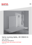
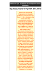
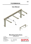
4SingleElectric
User Manual
Mounting Instructions
Keep this folder with product at all times!
PDF 6004 / 01.08.2009
Contents
1.
INTRODUCTION .............................................................................................................................................. 3
2.
CONFORMITY WITH EU-DIRECTIVES ..................................................................................................... 3
3.
APPLICATION .................................................................................................................................................. 3
4.
TECHNICAL DATA.......................................................................................................................................... 4
5.
SCHEMATIC DIAGRAM OF FRAME........................................................................................................... 5
5.
SCHEMATIC DIAGRAM OF FRAME........................................................................................................... 5
1.
MOTOR 96000553 2........................................................................................................................................... 6
6.
MOUNTING INSTRUCTIONS, DESCRIPTION....................................................................................... 7
6.1
6.2
6.3
6.4
6.5
Assembly of frame ..................................................................................................................................... 7
Mounting of safety strip............................................................................................................................. 8
Mounting of wheels (option) ..................................................................................................................... 9
Mounting of fixed control switch (option) ................................................................................................. 9
Performance test ....................................................................................................................................... 9
7.
LIST OF COMPONENTS ............................................................................................................................... 10
8.
OPTIONS .......................................................................................................................................................... 11
9.
SAFETY IN USE .............................................................................................................................................. 12
10. CLEANING/MAINTENANCE ....................................................................................................................... 13
10.1
10.2
10.3
Cleaning of frame.................................................................................................................................... 13
Maintenance............................................................................................................................................ 13
Service schedule, operation and maintenance ........................................................................................ 14
11. TROUBLE SHOOTING.................................................................................................................................. 14
11.1
11.2
11.3
The frame seems loose or unstable.......................................................................................................... 14
The height of the frame cannot be adjusted (adjustment seems very difficult)........................................ 14
The frame does not move straight ........................................................................................................... 14
12. CE-DECLARATION ....................................................................................................................................... 15
13. COMPLAINTS ................................................................................................................................................. 15
Page 2
1.
Introduction
4Single is a multi-function table, which may be adjusted electrically to suit seated or standing
activities. Owing to the unique design there are a variety of applications and the table is
therefore also ideal for wheelchair users.
This document must ALWAYS accompany the product and be read by and available to users.
All users must follow these instructions. It is very important that the instructions have been read
and understood prior to operation of the product.
The instructions should always be available to the user and must accompany the product in
case of relocation.
Correct use, operation and inspection are decisive factors for efficient and safe performance.
This product is electrically adjustable in height, which means that there is a risk of trapping.
The operation must therefore be made or supervised by an adult, who has read and
understood the importance of section 9 “Safety in use”.
The frame is provided with an infrared remote control, which must always be kept out of reach
of children.
2.
Conformity with EU-Directives
This product has CE-marking and meets the safety requirements of the Machinery, EMC and
Low Voltage Directives. See separate CE Declaration, section 12.
If the table frame is assembled with or is an integral part of other electrical components it will be
considered a new unit. Therefore, the assembled product must be subjected to a risk
assessment to obtain CE-marking.
3.
Application
4Single is designed to obtain optimum working height for the user. It is an activity table and
should therefore not be used as a lifting table or person lifter.
The product must be used indoor, under normal room temperatures and humidity as stated in
section 4. 4Single is not designed for use in damp rooms.
The control unit has IP32/ll protection and must always be installed in accordance with
the Danish Heavy Current Regulations or corresponding national or international
standards.
Page 3
4.
Technical data
Product name:
4SingleElectric
Item number:
Set of legs, Electric
Options:
Height 55-85 cm H1
50-41120
Height 65-95 cm H2
50-41220
Front fascias for frame L = xxx cm
From 60-200cm at increments of 1cm
50-43xxx
Side fascias for frame W = xxx cm
From 60-200cm at increments of 1cm
50-45xxx
Wheels:
Increase the table height by 7.5cm
Flexible safety strip
Material:
Welded steel tubes St. 37 and various plastic components
Surface treatment:
Blue chromate, powder coating: Standard CWS 81283 RAL
7021 mat
Power supply:
230VAC / 2.5A / 50Hz
Standby primary:
1.1W
Control voltage:
24VDC
Duty circle:
Max. 10% conform to 1 min. active / 9 min. pause
Max. load of frame:
130kg evenly distributed
Speed/lifting time:
Approx. 32 mm/sec. – approx. 10sec.
Increased load of frame:
250 kg evenly distributed (option)
Speed/lifting time:
Approx. 12 mm/sec. - approx. 25sec.
Temperature:
5-45°C
Air humidity:
5-85% (non-condensing)
Complaints:
See Complaints, page 15
Producer:
Ropox A/S, DK-4700 Naestved, Tel.: +45 55 75 05 00
e-mail: [email protected] - www.ropox.com
Page 4
5.
Schematic diagram of frame
All electrical connections to the control unit must be flexible to ensure that the table moves
freely within the range of adjustment.
Width 60 - 200cm
(Frame width always 0.4cm less
than table top, i.e. 59.6 – 199.6cm)
50cm
16cm
Width – 5cm
Length – 35cm
For table top length 60 - 200cm
(Frame length always 0.4cm less than the table top, i.e. 59.6 – 199.6cm)
Height: 55-85cm (H1)
Table size:
60cm < L ≤ 120cm
60cm < W ≤ 120cm
Height: 65-95cm H2)
Height w. wheels: + 7,5cm
Table size:
121cm < L < 200cm
121cm < W < 200cm
6cm
6cm
Page 5
11
7
10
9
3
1
4
13
3
2
8
12
5
6
Component
1. Motor
2. Motor cable 2m
3. Control unit
4. Side fascia shaft, Hex6. Length = frame width – 13.8cm
5. Infrared control switch Ropox 1 function
6. Angle plate for control unit
7. Leg 1
8. Leg 2
9. Allen screw M8x16
10. Side fascia profile Length = frame width – 12.4cm
11. Front fascia profile Length = frame length – 12.4cm
12. Screw ø4.8x13, Torx
13. Cover plates
Leg 1
Item number
96000553
96000573
96000563
96000661
*12978802-29
95010003
95091012
50*40000-025
Leg 2
Red
Black
Black
Red
Red
Black
Black
Leg 2
Red
Page 6
Leg 1
Pcs.
2
2
1
2
1
1
2
2
16
2
2
6
4
6.
Mounting instructions, description
Mounting must always be carried out by competent personnel.
Prior to mounting, check that all parts have been provided. See list of components, section 7.
6.1
Assembly of frame
6.1.1 Mount hexagonal shaft and motor cable.
6.1.2 Mount motor on side fascia. Free cut of
profile away from table top.
6.1.3 Check that the height (L) of all four legs is
identical. May be adjusted on hexagonal
shaft by means of the open-end wrench
provided. Place side fascias on a plane
surface and mount legs. See label on legs.
6.1.4 Now mount the two front fascias. Important:
Push side and front fascias firmly against the
leg before retightening the fascias. Tighten
the bolts securely by means of the wrench
provided.
1
6.1.5 Position the angle plate for control unit
as shown and fasten it to front fascia.
2
6.1.6 (1) Push the control unit over the fixture
and (2) fasten it.
Page 7
6.1.7 Place the frame on the table top and push
6.1.8 Fasten the tabletop with screws through the
the cover plates between legs and table top.
holes of the fascias.
Centre the frame in relation to the table top.
Connection to control unit
Connection of
safety strip
See 6.2.2
6.1.9 Connect the infrared receiver to the control
unit. Remove the protection paper and fit the
receiver under the table top. Place loose
cables in the cable clips and fasten them
under the table top.
6.2
Mains
cable
Motor cable
Cable for control
switch
6.1.10
Mounting of safety strip
Option: Ropox always recommends the use of safety strips on electrically
adjustable frames.
See the manual for strips provided.
Be careful not to damage the safety strip during transportation or mounting.
If the safety strip is bent or twisted too much it may not have the intended effect.
In order to obtain optimum adhesion the surface on which the safety strip is to be attached must
be clean and dry.
Long cable for upward
movement
6.2.1
Short cable for
downward movement
Push the safety strip through all four legs
and fit it on the underside of the fascia by
means of the double-adhesive tape
provided.
Remove the protection paper of the tape
and press on the safety strip. Observe the
minimum bending radius (2cm inside)
See separate instructions for mounting
and handling of the safety strip.
6.2.2
Short circuit plug (red)
Remove the red short circuit plug of the short
cable (marked in red).
Insert the loose cable of the safety strip into
the free socket of the control unit (cable
marked in red).
Page 8
6.3
Mounting of wheels (option)
6.3.1 Mount the wheels. Do not forget to fit three
washers on each wheel.
6.4
Mounting of fixed control switch (option)
6.4.1 Pull the cable through the front fascia and
insert it into the control unit.
6.5
Performance test
After mounting and prior to use all functions of the table must be tested. After that a
performance test must be carried out at least once a year by competent personnel:
1.
2.
3.
4.
5.
6.
7.
8.
Testing prior to switching on power:
Check that the mounting instructions have been observed.
Check that all bolts have been tightened.
Check that all cables have been connected correctly and that the plugs have been
pressed home.
There must be no load on the table.
There must be no objects or the like preventing the table from moving freely within the
range of height adjustment.
Now switch on power to the control unit:
Press the DOWN button and adjust the table to bottom position. Press the DOWN button
again and keep it pressed for another 5sec. to reset the control unit. Check that the
movement is smooth and even. Make sure that the mains cable moves freely.
Now press the UP button and adjust the table to top position. Check that the movement
is smooth and even. Make sure that the mains cable moves freely.
If a safety strip has been mounted under the tabletop it must be tested:
Press the DOWN button and let the table move 2-5cm downward while activating the
safety strip. The table must now stop the downward movement, move1-2cm upward and
stop.
When all these tests have been carried out the table is ready for use.
See ”Safety in use, section 9”.
Page 9
7.
List of components
Set of legs H1, 50-41120:
1 set
Set of legs H2, 50-41220:
1 set
Front fascias for L=xxx cm, 50-43xxx:
1 set
Side fascias for W=xxx cm, 50-45xxx:
1 set
Control unit (21,2x10,5x6,0cm) 50-41500:
230VAC, incl. mains cable (300cm)
1 pc.
Contained in control unit:
Infrared control 30-67847:
Remote control via infrared receiver (cable 250cm)
Operational range 150-200cm
1pc.
98002014 Y-cable for safety stop:
98002013 End plug with resistance:
1 pc.
2 pcs.
Adhesive plate 96000155:
5 pcs.
Strips black 96000165:
5 pcs.
Angle plate for control unit *12978802-29:
1 pc.
Motor 96000553:
2 pcs.
Motor cable 96000573:
2 pcs.
Allen screw M8x16 95010003:
16 pcs.
Screw ø4.8x13 95091012:
6 pcs.
Screw ø4.2x6.5 95090806:
2 pcs.
Page 10
8.
Options
Split cable for control switch 96000629:
To be used if more than one control switch is required
1 pc.
Control switch, small press pad (6 x 3cm) 30-67840:
1 pc.
Safety strip 30-69xxx:
1 pc.
Brake wheels, black (4 wheels) 50-41600:
Increase the table height by 7.5cm
incl. 12 washers (95170510)
1 set
Increased lifting power, set of legs H1, 50-41320:
Max. load 250kg evenly distributed
(To be ordered with main order)
1 set
Increased lifting power, set of legs H2, 50-41420:
Max. load 250kg evenly distributed
(To be ordered with main order)
Page 11
1 set
9.
Safety in use
¾
¾
¾
¾
¾
¾
¾
¾
¾
¾
¾
¾
¾
¾
¾
¾
¾
4Single must only be used by persons, who have read and understood these
instructions.
The frame is provided with an infrared remote control, which must always be kept out of
reach of children.
4Single is an electrically operated height-adjustable table and we recommend the use of
a safety strip in order to prevent damage and accidents. However, even if this strip has
been fitted, always make sure that there are no persons, animals or objects under the
table during use.
4Single is an activity table and should not be used as a lifting table or person lifter.
Always use the table in a manner excluding the risk of damage to persons or property.
The person operating the table is responsible for avoiding damage or injury.
Children or persons with reduced observation capability should only operate the table
when supervised.
If the table is used in publicly accessible locations where children or persons with
reduced observation capability may get near the table, the person operating the table
must pay attention to those present in order to prevent dangerous situations.
Make sure that there is free space above and below the table to allow height adjustment.
Do not operate the table in case of defects or damage.
Do not overload the table and make sure that the load distribution is correct.
Do not use the table in an explosive environment.
In connection with inspections, service or repairs always remove loads from the table.
When installing power or water connections, the regulations of the national authorities
must be observed.
Modifications, which may influence the operation or construction of the table, are not
allowed.
Installation, service and repairs must be carried out by competent personnel.
If the table has not been assembled according to these mounting instructions the right to
complain may become void.
Only use Ropox original spare parts as replacement parts. If other spare parts are used,
the right to complain may become void.
Page 12
10.
Cleaning/maintenance
10.1
Cleaning of frame
WARNING
The frame must NOT be connected to mains voltage during cleaning. Do
NOT flush electrical components with water.
Clean the frame with a wrung cloth with lukewarm water and a mild detergent. Do not use
enchants or abrasives or grinding cloths, brushes or sponges
Dry the frame after cleaning.
10.2
Maintenance
Inspections, service and repairs must be carried out by competent personnel.
The frame is maintenance-free and the moving parts have been lubricated for life. For reasons
of safety and reliability we recommend inspection of the frame once a year:
¾
¾
¾
¾
¾
¾
Check that all bolts have been tightened.
Check that the table moves freely and without problems from bottom to top position.
Resetting of frame: Press the DOWN button and adjust the frame to bottom position.
Press the DOWN button again and keep it depressed for 5 sec. to reset the control unit.
Check that the movement is smooth and even. Make sure that the mains cable moves
freely.
Check that water connection hoses and draining hoses, if available, are tight and
functional.
Check that cable to hotplate, if available, is undamaged and may move freely.
Check that all cables have been mounted correctly and are undamaged.
After each inspection, fill in the service schedule. See 10.3
Only use Ropox original spare parts for replacement of parts. If other spare parts are used, the
right to complain may become void.
Page 13
10.3
Service schedule, operation and maintenance
Service and maintenance Serial No.
Service and maintenance Serial No.
Date:
Date:
Signature:
Signature:
Remarks:
Remarks:
Service and maintenance Serial No.
Service and maintenance Serial No.
Date:
Dato:
Signature:
Signature:
Remarks:
Remarks:
11.
Trouble shooting
11.1
The frame seems loose or unstable
¾ The screws assembling the frame have not been securely tightened.
¾ Tighten all screws, cf. mounting instructions.
11.2
The height of the frame cannot be adjusted (adjustment seems very
difficult)
Check mains voltage to control unit and that the power has been switched on.
Check cables and plug-in connections between control unit and motors.
Check cable and plug-in connection between control unit and control switch.
Check connection of cables for safety strip to control unit and safety strip.
(If no safety strip has been fitted, there must be a short-circuit plug on the safety strip
cable. See mounting instructions fig. 6.2.2).
¾ If a safety strip has been fitted:
Check that the safety strip has not been activated.
Remove the short-circuit plug from the safety strip to the Y-cable of the control unit. See
mounting instructions fig. 6.2.2). If the table works without connection of the safety strip,
the safety strip has been activated.
¾
¾
¾
¾
11.3
The frame does not move straight
¾ If the frame does not move straight, it must be reset, see Maintenance, section 10.2
If there has been a power failure, the table must always be reset before use.
Page 14
12.
CE-Declaration
Product name:
4SingleElectric
Item number:
Set of legs, Electric
Height 58-88 cm, H1
50-41120
Height 65-95 cm, H2
50-41220
Front fascias for frame L = xxx cm
50-43xxx
Side fascias for frame W = xxx cm
50-45xxx
The above items conform to the following Directives and Standards:
DIRECTIVES
EU Council Directive No. 89/392/EEC concerning Machinery, modified by
Directive No. 98/37/EC
The Executive Order of the Danish Working Environment Service No. 561 of 24
June 1994 with subsequent modifications
73/23/EEC, The Low Voltage Directive, modified by Directive No. 93/68/EEC
89/336/EEC, The EMC-Directive modified by Directives Nos. 92/31/EEC and
93/68/EEC
STANDARDS
DS/EN ISO
DS/EN ISO
DS/EN
12001-1:
12100-2:
527-2:
2003
2003
2002
DS/EN
DS/EN
DS/EN
55014-1:
55014-2:
60335-1:
DS/EN
DS/EN
DS/EN
61000-6-3:2001, EN 55022 Class B
61000-3-2:2001, EN 61000-3-3:1995, A1:2001
61000-6-2:2001, EN 61000-4-2, -3, -4, -5, -6, -8, -11.
The original Declaration of Conformity is obtainable from Ropox A/S.
13.
Complaints
See General Terms of Sale and Delivery on www.ropox.com
Page 15
2000
1997
2002
ROPOX A/S
Ringstedgade 221
DK – 4700 Naestved
Tel.: +45 55 75 05 00 Fax.: +45 55 75 05 50
E-mail: [email protected]
www.ropox.com
Page 16