1
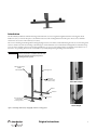
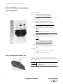
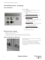
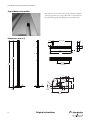
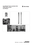
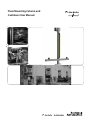
Floor Mounting Column and
Cantilever User Manual
Important User Information
Because of the variety of uses for the products described in this publication, those responsible for the
application and use of this control equipment must satisfy themselves that all necessary steps have been
taken to assure that each application and use meets all performance and safety requirements, including
any applicable laws, regulations, codes and standards.
The illustrations, charts, sample programs and layout examples shown in the guide are intended solely for
purposes of example. Since there are many variables and requirements associated with any particular
installation, Rockwell Automation does not assume responsibility or liability (to include intellectual property
liability) for actual use based upon the examples shown in this publication.
Rockwell Automation publication SGI-1.1, Safety Guidelines for the Application, Installation and
Maintenance of Solid-State Control (available from your local Rockwell Automation sales office), describes
some important differences between solid-state equipment and electromechanical devices that should be
taken into consideration when applying products such as those described in this publication.
Reproduction of the contents of this copyrighted publication, in whole or part, without written permission
of Rockwell Automation, is prohibited.
Throughout this manual we use notes to make you aware of safety considerations:
WARNING
IMPORTANT
ATTENTION
Identifies information about practices or circumstances that can cause an explosion in
a hazardous environment, which may lead to personal injury or death, property
damage, or economic loss.
Identifies information that is critical for successful application and understanding of
the product.
Identifies information about practices or circumstances that can lead to personal
injury or death, property damage, or economic loss. Attentions help you identify a
hazard, avoid a hazard, and recognize the consequences.
SHOCK HAZARD
Labels may be on or inside the equipment (for example, drive or motor) to alert people
that dangerous voltage may be present.
BURN HAZARD
Labels may be on or inside the equipment (for example, drive or motor) to alert people
that surfaces may reach dangerous temperatures.
It is recommended that you save this user manual for future use.
Introduction
The Allen-Bradley Guardmaster aluminum mounting stand is offered in a two meter length and is supplied with a floor mounting plate and the
hardware necessary to mount the floor plate to the aluminum extrusion as well as leveling hardware for the floor plate. The two meter aluminum
extrusion has a cross section of 60 x 60 mm (2.36 x 2.36 in.).
The two meter mounting stand is designed for mounting safety light curtains, corner mirrors, and the 445L muting box. The two meter mounting stand
can also be used for entry and exit end muting. A 500 mm long 60 x 60 mm aluminum section is offered with mounting hardware and a black end-cap
cover. One section attached to the two meter mounting stand allows an “L” type, two-sensor muting solution, two 500 mm sections allow for two- or
four-sensor “T” type muting. The slots in the extrusion allow easy assembly and positioning of muting sensors and reflectors.
IMPORTANT
If an “L” or “T” type configuration is
planned, it is best to assemble the 500 mm
sections to the two meter post prior to
installing the floor plate.
Muting Controller Box
(MSR42)
445L-AMUTBOX1
Mounting Stand
Light Curtain
(GuardShield Micro 400,
Safe 2, Safe 4 or 440L)
Micro 400 example
Reflector
Cantilever
Floor Mounting Plate
(included with
mounting column)
Muting Sensor
Safe 4 example
Figure 1: Mounting stand used for safety light curtain in a muting system
Original instructions
1
Floor Mounting Stand and Cantilever User Manual
445L-AMSTD2M Floor Mounting Stand
Step 1: Supplied parts
Pos Qty
Description
1
Profile 60 x 60 x 2000 mm (2.4 x 2.4 x 78.7 in.)
1 pc.
2
Floor plate to extrusion mounting hardware
4 pcs. Zinc hexagon socket head cap screws DIN 912 M6 x 25 mm
(0.98 in.)
6 pcs. Zinc washer (flat) M6 x 12 mm (0.47 in.)
8
3 pcs. Zinc set screw DIN 913 M12 x 12 mm (0.47 in.)
4
1 pc.
5
6
9
3
Aluminum, black anodized floor mounting plate
Micro 400 bracket hardware (bracket not included)
2 pcs. Zinc-plated T-slot nut 6 steel M4
2 pcs. Hexagon socket head cap screw DIN 912 M4 x 14 mm
(0.55 in.)
5
7
6
Brackets
4
445L-AF6145 Micro 400 flat bracket (not included)
7
Safe 4 bracket 445L-AF6140 hardware (bracket not included)
2 pcs. Zinc-plated T-slot nut 6 steel M6
2 pcs. Hexagon socket head cap screw DIN 912 M6 x 20 mm
(0.79 in.)
3
8
1
Brackets
445L-AF6140 Safe 2/4 bracket (not included)
2
9
Muting box hardware (muting box not included)
2 pcs. Zinc-plated T-slot nut 6 steel M5
2 pcs. Zinc washer (flat) M5 x 10 mm (0.39 in.)
2 pcs. Hexagon socket head cap screw DIN 912 M5 x 12 mm
(0.47 in.)
Not shown:
4 pcs. Cover profiles for hiding cables (aluminum, 300 mm
(11.8 in.))
1 pcs. Profile top cap 60 x 60 mm (2.4 x 2.4 in.)
Step 2: Assembling floor plate to post
Position the floor plate to the bottom of the two meter post with the
recessed holes opposite the post. Premount the screws with the washer in
the holes of the floor plate.
IMPORTANT
2
For use as a muting system, assemble
cantilevered arms prior to installing the floor
mounting plate.
Original instructions
Floor Mounting Stand and Cantilever User Manual
Step 3: Leveling hardware
Three hexagon socket head cap screws are supplied to level the floor plate.
If necessary, premount these screws before attaching the floor plate to the
aluminum post.
Step 4: Install profile covers
Four 300 mm profile covers are supplied with each two meter post to hide
the cables. Install these after the cables are assembled and connected. Use a
rubber mallet to secure these profile covers to the two meter post.
Step 5: Leveling the two meter post kit
When the floor plate is positioned and loosely secured to the floor, adjust each leveling screw to assure the two meter post is attached to the floor.
Then tighten the floor plate to the floor.
Original instructions
3
Floor Mounting Stand and Cantilever User Manual
445L-AMSTDMUT Cantilever—Assembly Steps
Step 1: Supplied parts
Pos Qty
Description
1
1 pc.
Aluminum profile 60 x 60 x 500 mm (2.4 x 2.4 x 19.7 in.)
1 pc.
Black end cap 60 x 60
1 pc.
Aluminum cover profiles for hiding cables (300 mm
(11.8 in.))
2
1
3
To attach cantilever post to the floor stand post
4 pcs. Stainless steel universal fastening set #6 (item no. 0044174)
2
4
4
5
3
6
8
7
6
1 pc.
Mounting kit for reflector (reflector not supplied)
1 pc. bracket 80 x 40 x 20 Zn (Item No. 0047463)
Bracket mounting hardware:
1 pc. washer (flat) M6 x 12 mm (0.47 in.) (zinc)
1 pc. hexagon socket head cap screw DIN 912 M6 x 16 mm
(0.63 in.)
1 pc. T-slot nut 6 steel M6, zinc plated
Reflector mounting hardware
1 pc. hexagon socket head cap screw DIN 912 M5 x 30 mm
(1.18 in.)
1 pc. washer (flat) M5 x 10 mm (0.39 in.) (zinc)
1 pc. hexagon nut DIN 934 M5 (zinc)
RightSight bracket 60-2649 mounting hardware
2 pcs. Hexagon socket head cap screw DIN 912 M6 x 14 mm
(0.55 in.)
2 pcs. T-slot nut 6 steel M6, zinc plated
Optional parts for muting—not supplied
8
7
5
RightSight retroreflective sensor 42EF-P2MPB-Y4
RightSight swivel/tilt bracket 60-2649
4-pin straight DC micro QD patchcord 889D-F4ABPM-X (X is length in meters) (not shown)
Large reflector 92-39 (76 mm (3 in.) diameter) or small reflector 92-47 (32 mm (1.25 in.) diameter)
Step 2: Assemble 500 mm cantilever post
Slide the four universal fastening sets in each slot on the left or the right side
of floor mounting stand.
Place the lower universal fastening sets at the desired height. Make sure that
the bezels of the lower universal fastening sets are on the upside.
Place the upper universal fastening sets about 100 mm higher than the
lower ones. Make sure that the upper bezels of the universal fastening sets
are on the underside.
4
Original instructions
Floor Mounting Stand and Cantilever User Manual
Step 3: Securing 500 mm cantilever to post
Hold the cantilever profile between the universal fastening sets. Using a #4
hex tool tighten the hex head screws.
Step 4: Installing muting sensors and reflectors
Mount the muting sensor to the bracket. Mount the muting sensor and the
bracket to the slot in the extrusion using the supplied hardware.
Step 5: Installing reflector
Mount the reflector to the supplied bracket. Mount the bracket to the
extrusion slot using the supplied hardware. Position the reflector and
tighten bracket hardware.
Original instructions
5
Floor Mounting Stand and Cantilever User Manual
Step 6: Mount cover profiles
Run cables in the slots once the system is complete. Finish the assembly by
positioning the profile covers. Using a rubber mallet or a block of material
that will not damage the material, lightly tap the cover profiles in place.
Dimensions [mm (in.)]
20 (0.79)
defined at installation
40
(1.57)
80
(3.15)
60
(2.36)
60
(2.36)
500 (19.69)
9.4
(0.37)
503 (19.80)
2000
(78.7)
300 (11.81)
cover for cable
locate appropriately
2015
(79.3)
24 (0.94)
2
30 (1.18)
3x
R5
.50
(0.2
M1
30 (1.18)
150
(5.91)
2)
60
(2.36)
12
(0.47)
60
(2.36)
100
(3.94)
10°
R 105
)
(4.13
14
30
(0.55) (1.18)
240 (9.45)
Base Plate
6
Original instructions
Floor Mounting Stand and Cantilever User Manual
Original instructions
7
Floor Mounting Stand and Cantilever User Manual
8
Original instructions
Floor Mounting Stand and Cantilever User Manual
Original instructions
9
GuardShield is a trademark of Rockwell Automation, Inc.
www.rockwellautomation.com
Power, Control and Information Solutions Headquarters
Americas: Rockwell Automation, 1201 South Second Street, Milwaukee, WI 53204 USA, Tel: (1) 414.382.2000, Fax: (1) 414.382.4444
Europe/Middle East/Africa: Rockwell Automation, Vorstlaan/Boulevard du Souverain 36, 1170 Brussels, Belgium, Tel: (32) 2 663 0600, Fax (32) 2 663 0640
Asia Pacific: Rockwell Automation, Level 14, Core F, Cyberport 3, 100 Cyberport Road, Hong Kong, Tel: (852) 2887 4788, Fax: (852) 2508 1846
10000127396 Ver 01
July 2011
Copyright ©2011 Rockwell Automation, Inc. All Rights Reserved. Printed in USA.