1
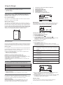
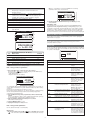
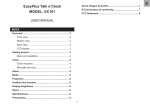
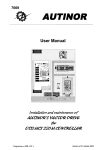
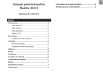
Technical Manual
GB
Hawker Lifespeed 3000
quis nostrud exerci tation ullamcorper
suscipit lobortis nisl ut aliquip
Model ATR 3015
Model ATR
ATR 3015
ENGLISH
Contents
Information
Summary...................................................................................... 3
Goals of this manual
Information.................................................................................. 3
Goals of this manual.................................................................................
This manual is aimed at any authorized personnel wanting to use a three
phase Lifespeed 3000 Series charger to recharge lead acid type industrial
batteries. This manual contains information on:
• Charger functionality.
• Use and setting of charger parameters.
• Technical specifications of the Lifespeed 3000 chargers.
Hawker intends to provide clear and simple information in this manual.
Hawker assumes no responsibility for misunderstanding or improper
interpretation of the information.
The owner of the equipment is required to preserve this manual for the
life of the equipment and to transfer said manual to any subsequent
purchaser.
3
Warranty..................................................................................................... 3
Recommendations..................................................................................... 3
Electrical safety.......................................................................................... 3
Product recycling........................................................................................ 4
Modifications and improvements............................................................. 4
Warranty
Receiving - Storage.................................................................................... 4
Warranty is offered by the manufacturer based on local regulations.
Please contact your local distributor for further information.
Replacement parts...................................................................................... 4
Information plate........................................................................................ 4
Recommendations
Glossary...................................................................................................... 4
Recommendations for safe operation
EEC declaration of conformity.................................................................. 4
This manual should be carefully read, prior to using the equipment, by
anyone intending to use the charger. The Lifespeed 3000 charger:
The Charger.................................................................................. 5
• Never disconnect a battery from the charger if in operation. Either •
allow the charger to terminate automatically or turn charger off prior
to disconnecting.
• This charger comes equipped with an anti-arcing connector. Any
battery used on this charger must be equipped with a matching
connector, and its auxiliary input wire must be connected to battery
positive (B+). Failure to make this connection will prevent the charger
from operating.
• The charger must not have its air circulation impaired in any way,
primarily around the air inlet areas. Dust accumulation must be
removed every six months
• The charger must be used within its protection norms, and never be
directly in contact with water.
• The charger must be used only within the temperature range specified
in the technical specifications.
• The charger must not be installed on a surface subject to high
vibration levels (proximity of motors, compressors, etc.).
Introduction................................................................................................ 5
External components................................................................................. 5
Control panel.............................................................................................. 5
The Menus.................................................................................... 6
Access to the menus.................................................................................
6
Memorized data......................................................................................... 6
Status.......................................................................................................... 7
Configuration.............................................................................................. 7
Contrast....................................................................................................... 7
Battery configuration
Backlight...................................................................................................... 7
Using the Charger........................................................................ 8
This charger is designed to be used with a Fast charge adapted battery.
Only batteries equipped with:
• An easyplus device with appropriate configuration
• Specific defined connectors in accordance with charging rates.
• Specific harness and battery plug equipped with auxiliary contacts.
may be used with this charger.
Unpacking................................................................................................... 8
Operator safety
Mechanical installation.............................................................................. 8
All proper precautions must be observed when the equipment is used in
areas where accidents are possible. Insure proper ventilation when the
charger is used with lead-acid batteries.
Do not disconnect the battery while the Lifespeed 3000 is charging.
Date / Time.................................................................................................. 7
Language..................................................................................................... 7
Electrical connections................................................................................ 8
Factory setup.............................................................................................. 8
General warnings
Charging the battery.................................................................................. 8
Requirements for use:
• The equipment must be properly grounded.
• The input voltage must match the charger requirements.
• The battery voltage must match the charger’s capabilities.
• The battery capacity is within the charger’s range.
Historical data per charge......................................................................... 9
Charger’s historical data............................................................................ 9
Fault codes.................................................................................................. 9
Electrical safety
Safety regulations and requirements must be observed. Safety devices
installed ahead of the chargers must be of the proper type and rating. It
is important to ensure that only fuses of the proper capacity be used,
should they need to be replaced. This charger meets the Class 1 Electrical
Safety requirements, and therefore needs to be properly grounded during
installation. It must be connected to a power supply equipped with a
ground cable, and the ground connection should be as short as possible.
The equipment must be totally disconnected from all power sources
(grid and battery) before it can be opened for inspection or servicing.
The battery can only be disconnected after the main ON/OFF switch has
been pushed to the OFF position. Access to the inside of the charger
should be restricted to authorized maintenance personnel.
3
Please consult a qualified factory representative about any problems or
questions related to the installation of this unit.
This charger is designed to be used in a sheltered area. It is meant
exclusively to recharge lead batteries in an industrial environment.
If the battery temperature, communicated by the easyplus, is too high,
the charger, before to start the charge, will switch on the air pump to
cool down the battery. During this time the charger will display the message ‘TEMP’. When the battery temperature is gone down to a specific
threshold the charger starts the charge.
No risk for the battery, the charger will switch automatically to the Ionic
profile if there are a fault on the air pressure or no communication with
the easyplus.
Complete recharging of the battery is done in short time, while energy
consumption is substantially reduced.
Product recycling
When this charger becomes obsolete, it can be recycled by authorized
recycling facilities. Local regulations will prevail and must be followed.
Modifications and improvements
Ionic profile
Also called “Ionic Mixing” this profile consists of applying short current
pulses to the battery, thus provoking gassing in the active material to diffuse the sulphuric acid off of the plates. This introduction of Ionic Mixing
permits a faster charging of the battery and eliminates the differences in
density by homogenizing the electrolyte throughout the cells. The ionic
profile is not high speed and requires standard recharge times.
Hawker reserves the right, at any time, to modify or improve its
products, without any obligation to update this product or this manual
accordingly.
Receiving - Storage
Upon reception, please inspect visually the exterior of the charger for
any possible damages. If necessary, proceed within 24 hours with the
usual claims with the transport company.
If the charger is to be stored before use, it should remain in the original
packaging, carefully closed. Store in a clean, dry area at a moderate
temperature (0 °C to +40 °C). If the equipment is stored at a temperature
below 15°C, it must be gradually restored to operating temperature
before use, to prevent the risk of condensation that could cause electrical
faults and short-circuits.
EEC declaration of conformity
Hawker hereby declares that the chargers in the Lifespeed ranges covered by this declaration conform to the descriptions laid
down in European Directives 89/336/EEC, 93/68/EEC and RoHS
2002/96/EEC.
Replacement parts
Please supply the unit’s serial number, indicated on the information plate
when ordering any replacement parts.
Information plate
Located on either side of the charger.
Glossary
Charger Features
The Lifespeed 3000 Series chargers are managed by a micro-processor.
The micro-processor reads the battery capacity from the easyplus and
sets the charge current appropriately. This allows the charger to work
over a wide range of battery capacity.
Charge factor
Charge factor is the quantity of Ampere Hours returned to the battery
during the charge cycle versus the amount removed during the last
discharge.
Refresh Charge
A refresh charge maintains the battery at the optimum level as long as it
is connected to the charger.
Desulphation charge
A desulphation charge is done prior to normal charging, and this charge
restores the specific gravity of overly discharged or underused batteries.
Equalization charge
Done after the normal charge, it balances out the various cells.
Hawker easyplus
The easyplus is permanently mounted to the battery and communicates
to the charger without the need for extra wires. Battery parameters
necessary for the optimization of the charging process are communicated
to the charger via the easyplus. The easyplus has an electrolyte level
sensor.
Charging profile
Defines the profile of the current applied to the battery during charging,
in relation to available time. The charger, coupled with easyplus, adapts
to the battery based on capacity and state of charge in order to maximize
overall battery life.
High Speed profile
Utilizing a specific patented algorithm, the electronic circuits of the
Lifespeed 3000 charger reduce the natural resistance of the battery by
introducing, at precise intervals, discharge cycles into the charging
profile. This homogenization of the ions around the plates allows for a
better distribution of the active ions in the charging zones.
A substantially larger current can therefore be applied and sustained,
resulting in a much faster charging process, while maintaining full
temperature control during the charge.
4
The Charger
Introduction
Control panel
The Lifespeed 3000 series of chargers are compatible with batteries at
24, 36, 48 and 80 volts (depending on the version supplied).
Battery recognition (voltage, capacity, state of charge, age, etc..) is
accomplished by communication from the easyplus. Battery management is optimized through use of the easyplus. Two charging profiles are
available (High Speed or IONIC) based on the configuration chosen by
the operator. Furthermore, desulphation, equalization and compensation
charges are integrated.
Incorporates the Display and Control Panel. Please refer to The Menus
(page 6) and Using the charger (page 8) for further details and features.
External components
1
1
2
3
3
4
4
5
6
5
2
quis nostrud exerci tation ullamcorper
suscipit lobortis nisl ut aliquip
7
Model ATR
ATR 3015
4
Ref.
Function
1.
Graphical LCD Display.
2.
Navigation button (UP)
3.
Accept / Select button.
4.
Navigation button (DOWN)
5.
RED fault indicator.
OFF: no fault.
6
1
Flashing: ongoing fault detected.
ON: fault.
6.
YELLLOW charging indicator.
OFF : charger is off.
ON : charging in progress.
Figure 1: Principal components of the wall and floor mounted
Lifespeed 3000 series charger models
7.
GREEN end of charge indicator.
OFF : charger off or battery not available
Flashing : cooling phase.
ON : battery ready and available.
1
2
8.
ON / OFF switch
9.
Menu exit, equalization start or desulphation start button.
Figure 2: Charger Display and Control components
6
Model ATR 3015
Ref.
Function
1.
Ventilation fins.
2.
Display and Control panel (see fig. 2).
3.
AC Input cable.
4.
Hood retaining screw.
5.
Wall mount.
6.
Battery cables.
5
The Menus
The Menus provide access to the following functions :
• Last 100 charging profiles (MEMORIZATIONS menu).
• Viewing of faults, alarms, etc.. (STATUS menu).
• Charger configuration (CONFIGURATION menu).
• Contrast adjustment (CONTRAST menu), backlighting of the display
(BACKLIGHT menu), date and time (DATE/TIME menu), language
(LANGUAGE menu) and display format (REGION menu).
Ref.
Information
1.
Battery serial number.
2.
Voltage, capacity & recorded temperature prior to charging.
3.
Detected profile.
4.
Alarm Icon (see Table A).
Icons Alarms
Access to the menus
!
Button functionality
The pads provide the following functions :
Alarms present.
Low electrolyte level.
Uneven battery voltage.
Pad
Function
▼▲
Navigation within the menu.
Missed equalization cycles.
OK
Select active menu or Select highlighted value.
Excessive overdischarge.
Close the window / Cancel.
Excessive daily cycles.
C
Excessive temperature.
easyplus disconnection.
Table A: Alarm icons.
MENU80 V– 85A
SMT
MEMORISATIONS
STATUS
CONFIGURATION
CONTRAST
BACKLIGHT
DATE /TIME
V3 . 3
Screen #2 (charger information)
SMT 80MEMO
V– 85A 1
Each of the eight available menus is described below (the last menu
lines LANGUAGE and REGION are only visible after pressing the ▼).
V3 . 3
IONIC
2. 33
3Ah
47 % 30°C
2. 40V/26A
00 : 07
DF5
CFC=0x0100C802
1
2
3
4
5
Escape a Menu
The active menu is automatically cancelled after one minute of inactivity
or by pressing
.
Ref.
Memorized data
1
Displays historical data from the last 100 charge cycles.
Information
Type, state of charge and temperature recorded prior to
the charge.
2
Access
Voltage per cell before and after charging, and current at
termination of charge.
From the main menu select MEMORIZATIONS and press OK.
The List screen
3
Capacity restored and total charging time (format hr:min).
4
End of charge condition icon :
Normal.
The sample screen below indicates that 17 records exist (title line).
MEMO 1 refers to the latest record. After the 100th record is memorized,
the oldest will be replaced automatically.
MEMORISATIONS
SMT
80 V– 85A
MEMO
1
MEMO
2
MEMO
3
MEMO
4
MEMO
5
MEMO
6
Normal with interruption (voluntary or caused by a fault).
Type and time of fault (see Fault Codes, page 9).
5
(17)
V3 . 3
Coded end of charge indicator.
Screen #3 (connection, disconnection)
MEMO MEMO 1
1
2
3
4
To view a charge history
Proceed as follow:
1.
2.
3.
4.
5.
Select a record (MEMO x) by pressing ▼ or ▲.
View the first screen by pressing OK.
View the second screen by pressing ▼.
View the third screen by pressing again on ▼.
Return to the main menu by pressing
.
Displayed information
The charge profile history is displayed on three screens.
Screen #1 (battery information)
17/06/2005 14:17
Ref.
Information
1.
Battery connected symbol.
2.
Time and date of battery connection.
3.
Battery disconnection symbol.
4.
Time and date of battery disconnection.
Reset of displayed information
Resetting the information displayed on these three screens is done by
pressing the Reset command from the CONFIGURATION menu (see
page 7).
MEMO MEMO 1
1
2
3
4
16/06/2005 16:41
CA11402
48V 500Ah 30°C
IONIC
!
6
For example, choosing Monday will start the equalization process every
Monday, based on a duration and delay programmed under
Equalization Time and Equalization Delay. The equalization can be
started automatically or manually. See paragraph End of Charge with
Equalization on page 9.
Status
This menu displays the charger’s internal counters (number of normal
charges, of equalization charges, faults by type, etc..)
Access
Delayed Charge
From the main menu select STATUS and press OK.
Two way to set a delay charge:
• Defines a delay between 0 and 8 hours between the time that the
battery is connected, and the actual start of the charging process.
• Defines an hour to start the charge (hh:mm), if the battery is
connected to the charger the charge will start at the program hour.
Allows for charging during “Off peak” periods.
The Screen
Information is displayed on one screen.
As an example:
Battery Rest
STATUS
SMT
80 V– 85A
CHARGE
20
6
14
EQUAL
5
TH
0
DF1
0
V3 . 3
DF2
0
DF3
0
DF4
0
DF5
0
DF7
1
DF8
0
DF9
0
Defines a waiting period from 0 to 8 hours after the end of the charge to
allow the battery to cool off.
Cable Length
Length of battery cable from the connector to positive post of battery.
Acceptable range is from 1 to 10 meters.
The above display corresponds to the following data:
This parameter is very important as it directly affects
characteristics of the charging profile.
Indication Information
Charge
Cable Section
Total number of charges. Corresponds to the total of
Determines the cross-section of the battery cables in mm2.
Select a section from the list displayed. If different sizes are being used
on the battery and the charger, enter the smaller of the two.
normally terminated charges and charges terminated
with or by faults.
Number of charges terminated abnormally.
This parameter is very important as it directly affects
characteristics of the charging profile.
Number of charges normally terminated.
EGAL
Reset
Number of equalization charges completed by the
charger.
TH
Number of temperature faults*.
DF1 etc.
Number of faults recorded by the charger (see Fault
Resets the counters in Status and Memorized Data after you put in the
password; this password is different than the one used to enter into
Configuration.
Version config
Codes on page 9).
Shows the charger’s configuration version.
Reset of displayed information
Resetting the information displayed on these three screens is done by
pressing the Reset command from the CONFIGURATION menu.
Contrast
Modifies the display contrast level. A value of 0 displays a white screen ;
a value of 100 displays a black screen.
Configuration
This menu leads to the ten charger configuration menus.
The optimum value varies with ambient light. If you cannot read the
screen (screen black or white):
1. Press and hold
and ▲ at the same time.
2. When the LEDs start flashing (Fig. 2), adjust the contrast with the
▼ or ▲ pads.
3. Confirm by pressing OK.
Access
With the charger at rest (main switch on « 0 »), press OK. On the first
menu select CONFIGURATION and press OK. Use the two ▼ and ▲
pads to display the number corresponding to your password and confirm by pressing OK. The main menu will come up.
Backlight
Profile
Activates (ON) or deactivates (OFF) the display’s backlighting system.
Determines the charging profile for the battery connected (Ionic or Fast).
To change the profile, press OK, select a profile from the list with the
▼ ▲ pads and confirm by pressing OK.
Date / Time
Adjusts system date and time. Use the ▼ or ▲ pads to increase or
decrease the values. Use the OK button to switch from date settings to
time settings. Press the
confirm and exit the menu. CAUTION: Time
and date are only saved for three days if the charger is disconnected.
Temperature
Sets the battery’s starting operating temperature between 0°C and 55°C.
Please note that the scale displayed is in function of the Region selected
in the Configuration.
Language
This selects the language displayed in the menus.
• With easyplus: the battery’s operating temperature is set
automatically. It is highly recommended, especially in colder
environments to enter the battery’s average temperature value.
Equalization
Equalization can be started manually or automatically at the end of
charge. See the paragraph End of Charge with Equalization on page 9.
Equalization time
Sets the duration from 1 to 48 hours.
Equalization delay
Sets the start delay from 0 to 8 hours.
Frequency
Defines in real time the equalization periods (Never, Daily, Monday,
Tuesday, Wednesday, Thursday, Friday, Saturday, Sunday).
7
Using the Charger
1.
2.
3.
4.
5.
6.
7.
Unpacking
The Lifespeed 3000 is delivered with the following:
• 3 m battery cables.
• This user’s manual.
Mechanical installation
Charger type and model (LS stands for Lifespeed).
Charger characteristics.
Wait mode (line voltage 400).
Last charging profile selected.
Firmware version.
System time and date (optional).
Selected battery operating temperature.
Any area subject to water or spills of any kind must absolutely be
avoided. The table on page 10 provides all of the pertinent physical
dimensions of the equipment.
Floor mounted chargers
This applies to models 3020 and 3030. The minimum distance allowed
between two chargers must be 0.30m.
1
2
LS3010 24-36-48V
V1. 0
30/11/05 16:43
3
L400
4
FAST
5
6
7
30°C
Wall mounted chargers
Delayed Start
If the charger was programmed for delayed start (Configuration menu /
Delayed Start), charging will begin following that delay. The display
shows the time remaining before the programmed charging starts.
This applies to models 3010 and 3015. The unit must be mounted in a
vertical position. The bottom of the charger must be at least 0.60m from
the floor and/or the charger below and the top of the unit at least 1.0m
from the ceiling. The minimum distance between two chargers must be
0.30m. You must avoid areas where the chargers may be splashed with
water. The charger is held by 4 M8 screws suitable for the type of
support. For the drilling pattern follow the illustration below.
LS3010 24-36-48V
394
V1. 0
H = 01 : 59 : 41
FAST
30°C
Starting a Desulphation cycle
To
1.
2.
3.
540
mm
Electrical connections
start the desulphation cycle manually:
Push the ON/OFF switch to « 0 ».
Press and hold the button
.
Push the ON/OFF switch to « 1 ». Release the
.
Desulphation will now run for the programmed time. The standard
charging cycle will have to be started manually after the
desulphation cycle is complete.
Starting the Charge cycle
Three phase input
1. Push the ON/OFF switch to « I ».
The display shows various information relative to the battery
connected to the charger, and counts down the time remaining until
the effective charge begins.
Connection to the grid will be 400 volts / 3-phase and be done through a
proper plug and adequately sized circuit breaker (not included). Current
requirements in Amps are indicated on the charger’s information plate.
Battery output
It is essential to ensure proper polarity. However, reversed polarity will
result in blowing the output fuse, inability to charge, and the fault code
DF2 to be displayed. See Fault Codes on page 9.
Ref.
Information
1.
Charger type, voltage and current information and firmware
version.
2.
Connection to the battery will be done through the supplied cables:
• RED Cable: Battery POSITIVE.
• BLACK Cable: Battery NEGATIVE.
Maximum of two minutes countdown before the effective
charge begins.
3.
Detected charging profile will be flashing as information is
received. (a).
Additional note for Lifespeed 3000 model 3030 only:
Because of the high current level generated by this unit, two
independent sets of cables will be supplied. The MASTER cables will be
equipped with air connector. These will be connected to the
corresponding connectors on the battery.
The MASTER & SLAVE connectors must always be connected for the
charger to operate.
4.
is received (a).
5.
Possible fault display area, after 2 minutes (see § Fault Codes
6.
Operating temperature as detected (a) (c).
on page 9) (b).
7.
Factory setup
As ordered
Output cables length:
4m
Configuration:
As ordered
Automatic equalization:
No
Delayed start enabled:
No
Icon for requested equalization after charging (see § End of
charge with Equalization on page 9).
The Lifespeed 3000 is delivered with the following default setup :
Profile:
Alternates between serial number and capacity as information
1
LS3010 24-36-48V
S/N : CA11402
V1.0
4
5
2
3
• If no modifications are required, go directly to the section:
Charging the Battery.
• If changes are needed, go to the Configuration section on page 7.
H = 00 : 02 : 00
IONIC
30°C
6
7
(a) After the two minutes of countdown, the display shows information
relative to the charging process. See the paragraph on
«Effective charge».
(b) The following faults will prevent charging: DF1, DF2, DF3, TH, TEMP
and STOP; they will be displayed after the 2 minute countdown.
See paragraph «Fault codes» on page 9.
Charging the battery
It is now assumed that the charger has been set up as per the
Configuration, on page 7. Charging can only begin with a battery of the
proper type, capacity and voltage connected to the charger.
Effective charge
Off Charge Display
With the Lifespeed 3000 in wait mode (On/Off switch in the « 0 »
position) and without pressing the OK button, the display shows
information relative to the charger on the top and bottom lines:
A few moments into the effective charge, the display will begin
alternating between the following charging information:
8
Ref.
Information
1.
Charger type, voltage and current information and
EGAL I = (equalization current) and EGAL H = remaining
equalization time) (ref. 1 and 2 below).
LS3010 24-36-48V
MEMO 1
firmware version.
2.
Possible priority alarm (the
shows up within the battery
V1.0
EQUAL
H= 02:00
symbol, if the electrolyte level is low in the battery), only
available when battery is equipped with the easyplus
30°C
EQUAL
1
2
3.
Equalization requested after the charge.
4.
Operating temperature as detected.
5.
Detected charging profile.
6.
Alternates detected serial number and capacity.
Automatic start
7.
Indicates charge (7a) or discharge (7b) cycles.
8.
Cycled updated information. Please refer to Table B on
If equalization has been already programmed (Configuration Menu,
Equalization time, Equalization delay, and Frequency (page 7), the
equalization charge will start automatically. Also, if the battery remains
plugged in, in order to maintain an optimal charge, refresh and equalization
charges will be automatically triggered, if selected, based on battery type.
The same information as for the manual start (see above) will be displayed.
2. The battery will be available when the green LED (Fig. 2, ref.7)
comes back on.
page 9 below.
1
2
3
4
5
LS3010 24-36-48V
S/N : CA11402
V1.0
6
CHARGE
30°C t=00 : 32
Historical data per charge
7a
For viewing and resetting of historical data, please refer to paragraph
Memorizations on page 6.
8
FAST
Charger’s historical data
LS3010 24-36-48V
S/N : CA11402
V1.0
DISCHARGE
30°C t=00 : 32
For viewing and resetting of the charger’s history, please refer to
paragraph Status on page 7.
7b
Fault codes
In case of a fault, the display shows the corresponding fault code (DF1 in
the example below). When several faults are present, the fault codes will
be cycled on the display.
LS3010 24-36-48V
V1.0
MEMO 1
FAST
Cycled information (ref. #8 above)
DF1
Sign
Measurement
Example
U
Battery voltage (V).
26.1
u
Voltage per cell (V).
2.18
I
Actual charging current (A).
55
C
Capacity restored (Ah).
71
Fault
Cause
t
Total charging time (hrs:min).
03:36
DC
Shows up prior to DF1 fault.
DF
Eventual fault code. See § Fault Codes on page 9. DF5
DF1
Charger problem.
Critical fault. Check input
voltage.
DF2
Output fault.
Critical fault. Check for
proper battery connection
(reversed polarity).
Check output fuse.
DF3
Improper battery.
Critical fault. Battery
voltage too high or too
low. Use proper charger
for battery.
DF5
Battery requires inspection.
Non critical fault. Check
battery cables for condition
and size, check for loose
connections, check for
defective cells.
DF7
Pneumatic mixing air circuit
fault (the red light flashes).
Check the air circuit
(pump, tubing). The
charging operates in
IONIC profile if there is
an air circuit fault.
DF8
Communication fault between 3020 and 3030 models
the charger’s internal modules. only. Non critical fault.
Contact servicing agent.
DF9
Fault in discharge circuit.
Non critical fault. Contact
Charger reverts to Ionic profile. servicing agent.
STOP
Critical battery electrolyte level. Critical fault. Top up
battery electrolyte (only
indicated if using easyplus).
TEMP
Critical battery temperature.
Critical fault. The charger
is waiting that the battery
temperature goes down
to start the charge (only
indicated if using easyplus).
TH
Thermal problem in charger
resulting in charge
interruption.
Critical fault. Check that
fans are working. Verify
that ambient temperature
is not too high. Inspect to
see if charger ventilation
is obstructed or impaired.
FAST
Table B: Information icons (during charge).
End of charge without equalization
1. The green LED comes on after a proper end of charge.
The green LED
is on and the display shows AVAIL (ref. 1).
The display alternates between (ref. 2) :
• Total charging time.
• Amp/hrs restored to the battery.
LS3010 24-36-48V
25 °C
IONIC
V1.0
AVAIL
t=02:00
1
2
See paragraphs Memorizations (page 6) or Status (page 7) for details on
end of charge information. Any other lit LED indicates a problem during
charging.
Please refer to paragraph Control Panel on page 5.
If the battery remains plugged in, in order to maintain an optimal charge,
refresh and equalization charges will be automatically triggered, if
selected, based on battery type.
2. If an equalization charge was programmed, it will be automatically
started.
If not, an equalization charge can be started manually at this point; go
to paragraph End of Charge with equalization below.
3. If the green LED is flashing, the battery is in rest mode.
Wait until the flashing stops.
4. Push to ON/OFF switch to « 0 ».
5. Unplug the battery. It is ready for use.
End of charge with equalization
Can be started manually or automatically.
Manual start
1. At the end of charge (green LED
on or flashing), press on the
. The start of the equalization charge is indicated by the message
9
30°C
Solution
10
A
Auxiliary
With Air and
1 to 10
Subject to technical modification without any prior notice.
Wall Mounting
Wall Mounting
120
750 x 410 x 317
mm
Dimensions (H x W x D)
750 x 410 x 317
LCD
kg
Weight
0 to +40
Display
Operating temperature
DIN43589-1 320A
Protistor 63A
10
70
40
80V
Cabinet
859x728x697
70
With Air and Auxiliary
95
35
50/60
20
LS3020
400 ±10% / 3 ph
48V
(3)
60
Auxiliary
Auxiliary
60
With Air and
With Air and
DIN43589-1 160A
50
27
80V
IP20
°C
6
Protistor 40 A
DIN43589-1 320A
70
DIN43589-1 320A
50
Protistor 32 A
25
24/36/48V
15
LS3015
IP Protection
m
mm2
4
17
24/36/48V
10
LS3010
(Default )
Battery cables length
DC Plug
Battery cables
Input fuse
mm2
A
Nominal current draw
Input cable (4x)
V
Hz
Frequency
KW
Power
Input voltage
Units
Specification
TECHNICAL SPECIFICATIONS
120
Auxiliary
With Air and
Cabinet
859x728x697
Auxiliary
With Air and
DIN43589-1 320A
2 x DIN43589-1 320A
55
95
Protistor 80 A
16
80V
2 x 70
50
48V
30
LS3030
Cabinet
12/2006
859x728x697
140
Auxiliary
With Air and
2 x DIN43589-1 320A
2 x 70
Protistor 100 A
16
75
80V
40
LS3040
Wherever in Europe you do business, Hawker
can support you with motive power energy.
The Hawker branded battery range, matched
chargers and systems provide trouble free
performance under the most demanding
service conditions.
Our strategically located manufacturing plants
are efficient and responsive with a culture of
continuous improvement and added value for
our business partners.
Hawker has an enviable position in technology
leadership and with significant investment in
research and development we intend to stay
at the leading edge in product innovation.
Hawker evolution batteries and Hawker HF
chargers, Lifeplus and Powertech have set
new standards in maintenance free solutions.
Our team of development engineers is driven
by the desire to build the best energy solutions
and works closely with our customers and
suppliers to identify development opportunities.
Our bias for rapid innovation means we get new
products to market fast.
European Headquarters:
EnerSys EMEA
EH Europe GmbH
Löwenstrasse 32
8001 Zürich
Switzerland
Phone: +41 (0)44 215 74 10
Fax:
+41 (0)44 215 74 11
www.enersys-hawker.com
Hawker S.A.R.L.
Rue Alexander Fleming
ZI EST BP 962
62033 Arras cedex
France
Phone: +33 3 21 60 25 25
Fax:
+33 3 21 73 16 51
Please refer to the website
address for details of your
nearest Hawker office
04/2007 - Subject to revisions without prior notice
Hawker's integrated sales and service network
across Europe is dedicated to providing our
customers with the best solutions and after-sales
support for their business. Whether you require
1 battery or a complete fleet of batteries, chargers,
a battery handling system and a state of the art
fleet management system, you can count on us.
As part of EnerSys the world's largest
industrial battery manufacturer, we are
dedicated to being the best.