1
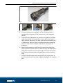
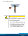
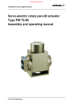
Translation of the Original Manual
Junction box
J-BOX
Assembly and Operating Manual
Superior Clamping and Gripping
Translation of the Original Manual
Imprint:
Copyright:
This manual remains the copyrighted property of SCHUNK GmbH & Co. KG. It is solely
supplied to our customers and operators of our products and forms part of the unit. This
documentation may not be duplicated or made accessible to third parties, in particular
competitive companies, without our prior permission.
Technical changes:
We reserve the right to make alterations for the purpose of technical improvement.
Document number:
Edition: 1.0 |March 14, 2014|en
© SCHUNK GmbH & Co. KG, Lauffen/Neckar
All rights reserved
Dear customer,
congratulation on choosing a SCHUNK product. By choosing SCHUNK, you have opted
for the highest precision, top quality and best service.
You are going to increase the process reliability of your production and achieve best
machining results – to the customer's complete satisfaction.
SCHUNK products are inspiring.
Our detailed assembly and operation manual will support you.
Do you have further questions? You may contact us at any time – even after purchase.
Kindest Regards
Yours SCHUNK GmbH & Co. KG
Precision Workholding Systems
Bahnhofstr. 106 – 134
D-74348 Lauffen/Neckar
Tel. +49-7133-103-2503
Fax +49-7133-103-2189
[email protected]
www.schunk.com
QM.UC.00015-R1.0 |en
Table of contents
Table of contents
1
About this manual .................................................................................................... 4
1.1 Warnings ................................................................................................................... 4
1.1.1 Signal words .................................................................................................. 4
1.1.2 Symbols ......................................................................................................... 4
2
Basic safety notes .................................................................................................... 5
2.1 Intended use ............................................................................................................. 5
2.2 Environmental and operating conditions................................................................. 5
2.3 Product safety........................................................................................................... 6
2.3.1 Protective equipment ................................................................................... 6
2.4 Personnel qualification ............................................................................................. 6
2.5 Using personal protective equipment...................................................................... 7
2.6 Notes on particular risks........................................................................................... 7
3
Warranty .................................................................................................................. 8
4
Scope of delivery ...................................................................................................... 9
5
Technical Data ......................................................................................................... 10
5.1 Identification plate ................................................................................................. 11
Description .............................................................................................................. 12
6.1 Functioning description .......................................................................................... 12
6.2 Product description ................................................................................................ 13
6
7
Installation and connection ..................................................................................... 16
7.1 Installation .............................................................................................................. 16
7.2 Connection ............................................................................................................. 18
8
Initial commissioning and normal operation ............................................................ 24
8.1 Initial commissioning .............................................................................................. 24
8.2 Normal operation ................................................................................................... 27
9
Troubleshooting ...................................................................................................... 28
10 Servicing and maintenance ...................................................................................... 29
11 Transportation and storage ..................................................................................... 31
11.1 Transportation ........................................................................................................ 31
11.2 Storage .................................................................................................................... 31
12 Disposal .................................................................................................................. 32
13 Spare parts .............................................................................................................. 33
QM.UC.00015-R1.0 |en
3
About this manual
1 About this manual
This instruction is an integral part of the product and contains important information for a safe and proper assembly, commissioning, operation, maintenance and helps for an easier trouble shooting.
Before using the product, read and note the instruction, especially
the chapter "Basic safety notes".
1.1 Warnings
The following signal words and symbols are used to highlight dangers.
1.1.1 Signal words
DANGER
Dangers for persons.
Non-compliance will inevitably cause irreversible injury or death.
WARNING
Dangers for persons.
Non-compliance may cause irreversible injury or death.
CAUTION
Dangers for persons.
Non-observance may cause minor injuries.
CAUTION
Information about avoiding material damage
1.1.2 Symbols
Warning about a danger point
Warning about dangerous electrical voltage
Danger of magnetic field
Danger of falling down workpieces
General mandatory sign to prevent material damage
4
QM.UC.00015-R1.0 |en
Basic safety notes
2 Basic safety notes
2.1 Intended use
This junction box has exclusively been designed as a connection
between SCHUNK electro-permanent-chucks and SCHUNK electronic control units, meant to operate machine tools for the metal
cutting processing of workpieces.
This junction box must be positioned and installed in a place complying with its corresponding IP-class.
The requirements of the applicable standards must be observed
and complied with. The junction box may be used only in the context of its defined application parameters.
To use this unit as intended, it is also essential to observe the
technical data and installation and operation notes in this manual
and to comply with the maintenance intervals.
DANGER
Danger to short circuit
• The junction box must be installed outside of the machine tool
and must always be protected against water and/or operating
fluids from the machine and protected against metal chips.
NOTE
This junction box must not be put into service until the machine
tool, for which the junction box is provided, satisfies the requirements of the Machinery Directive 2006/42/EC!!
2.2 Environmental and operating conditions
• Use the junction box only within its defined application parameters. "Technical data" ( 5, Page 10).
• Make sure that the environment is clean and the ambient temperature corresponds to the specifications.
QM.UC.00015-R1.0 |en
5
Basic safety notes
2.3 Product safety
Dangers arise from the use of the junction box, if e.g.:
• the junction box is not used in accordance with its intended
purpose.
• the junction box is not installed or maintained properly.
• the safety and installation notes are not observed.
Avoid any manner of working that may interfere with the function
and operational safety of the junction box.
Wear protective equipment.
NOTE
More information is contained in the relevant chapters.
2.3.1 Protective equipment
Provide protective equipment as per EC Machinery Directive.
2.4 Personnel qualification
Installation, connection, maintenance, and repair of the junction
box may be performed by trained specialist personnel, only. Every
person called upon by the operator to work on the junction box
must have read and understood the complete assembly and operating manual especially the chapter "Basic safety notes" ( 2,
Page 5). This applies particularly to personnel only used occasionally, such as maintenance personnel.
6
QM.UC.00015-R1.0 |en
Basic safety notes
DANGER
Danger due to a magnetic field.
The junction box is always linked to the use of a magnetic system.
The following persons must not come into contact with it:
• Persons with pacemakers.
• Persons with metal or electronic prostheses.
• Persons with insulin pumps.
• Persons with muscular stimulation systems.
• Pregnant women.
These persons should always keep a safe distance of at least 2m
to the system.
2.5 Using personal protective equipment
When using this product, observe the relevant industrial safety
regulations and use the personal protective equipment (PPE) required!
• Use protective gloves, safety shoes and safety goggles.
• Observe safety distances.
• Minimum safety requirements for the use of equipment.
2.6 Notes on particular risks
• Remove the power supply before installation, modification,
maintenance, or adjustment work.
• Ensure that no residual energy remains inside the system.
• Perform maintenance, modifications, and integrations outside
the danger zone.
• For all work, secure the junction box against accidental operation.
QM.UC.00015-R1.0 |en
7
Warranty
3 Warranty
The warranty is valid for 12 months from the delivery date to the
production facility under the following conditions:
• Intended use in 1-shift operation
• Observe the mandatory maintenance intervals.
• Observe the environmental and operating conditions.
Parts touching the work piece and wearing parts are not part of
the warranty.
Procedure in the The buyer agrees to send a written detailed report on newly disevent of warranty covered defects of the junction box to SCHUNK within 10 days after identification.
8
QM.UC.00015-R1.0 |en
Scope of delivery
4 Scope of delivery
Fig. 1
The Junction box will be delivered as complete unit.
QM.UC.00015-R1.0 |en
9
Technical Data
5 Technical Data
Tipo
0420184
0420185
0420186
0422940
0422941 0422942 0422943 0422944 0422945 0422946
Mains voltage
Depending on the control unit
Frequency
Depending on the control unit
Phases
Depending on the control unit
Rated current
Depending on the control unit
Rated short circuit
current
Depending on the control unit
IP rating
IP20, after the fastening of each connector
Activation time
~2s
~4s
Activation change
Weight
~3s
~5s
~6s
~7s
~8s
~6s
~8s
1 (de-) magnetization - max. every 3 min.
~4 kg
~7 kg
Ambient temperature
Ambient conditions
10
~4s
QM.UC.00015-R1.0 |en
~4 kg
~6 kg
~9 kg
~10 kg ~12 kg ~13 kg ~6 kg ~7 kg
5° - 55° C
Operation in dry interiors
with a relative air humidity of approx. 5 - 15%
Protect product from caustic vapours and excessive heat
Technical Data
5.1 Identification plate
The identification plate is on the backside of the junction box:
Fig. 2
Information
Description
Id. No.
Product code no.
Type
Model
Serial No.
Product serial no.
Work No.
Product production no.
Voltage
Rated voltage (mains)
Frequency
Rated frequency (mains)
Channels
Number of output channels
Phases
Phases (mains)
Current
Rated current (mains)
Lcm
Rated short-circuit data
Year
Year of manufacture
Weight
Weight
The identification plate must never be removed! Please always
have the serial no. at hand when contacting SCHUNK about technical matters.
QM.UC.00015-R1.0 |en
11
Description
6 Description
6.1 Functioning description
By using the electronic junction box linked to a SCHUNK control
unit, the operator is able to magnetize and to demagnetize small
and large electro-permanent magnetic chucks connected to the
same.
By means of this junction box, the operator can use a single control unit for the magnetization of several magnetic chucks (up to
8), thus optimising at best the efficiency of the entire magnetic
system.
The magnetization time depends on the type of junction box applied.
12
QM.UC.00015-R1.0 |en
Description
6.2 Product description
TYPE:
TYPE: 0420184
TYPE:
TYPE: 0420185
TYPE:
TYPE: 0420186
TYPE:
TYPE: 0422940
QM.UC.00015-R1.0 |en
13
Description
14
TYPE:
TYPE: 0422941
TYPE:
TYPE: 0422942
TYPE:
TYPE: 0422943
TYPE:
TYPE: 0422944
0422944
QM.UC.00015-R1.0 |en
Description
TYPE:
TYPE: 0422945
TYPE:
TYPE: 0422946
Fig. 3
The delivery includes:
Pos. n.
(1)
Description
1
Aluminium junction box.
2
Input multi-pole connector(1)
3
Metal coated output discharge cable and end connector
(1)
for the connection to the magnetic chuck. The cable
length is of five (5) meters
The type of connector changes according to the type of junction box.
QM.UC.00015-R1.0 |en
15
Installation and connection
7 Installation and connection
7.1 Installation
1 Open the packaging and take out the junction box.
2 Check the junction box for transport damage!
3 Compare the junction box with the specifications given in the
order!
4 Visually inspect the connection cable for damages. (Notches?
Abrasion? Cuts?)
5 Carry out the installation of the junction box by means of the
(4) fixing holes. In the following the centre-to-centre distance
of these holes:
TYPE: 0420185
TYPE: 0422940
TYPE: 0422942
TYPE: 0422943
TYPE: 0422944
TYPE: 0422945
TYPE: 0422946
TYPE: 0420184
TYPE: 0420186
TYPE: 0422941
Fig. 4
16
QM.UC.00015-R1.0 |en
Installation and connection
CAUTION
Danger caused by a sudden falling down of the junction box.
• An inadequate fixing can cause the falling down of the junction box with a consequent risk of injury for the operators.
6 Apply if necessary a protective cover (complying with the IP
class indicated at paragraph 5) to the junction box in order to
prevent the same from being exposed to continuous water
splashes caused during the working process.
NOTICE
Damage to the junction box as a result of a short-circuit.
The junction box could be damaged by oil and water.
• The positioning of the junction box inside the machining area
should be avoided during its installation and operation;
QM.UC.00015-R1.0 |en
17
Installation and connection
7.2 Connection
After having installed the junction box in a place complying with
the requirements indicated at paragraph 7.1, the connection
between the same, the magnetic chucks and the control unit must
be carried out.
DANGER
Danger due to electric shock!
Touching live parts can cause death by electric shock.
The connection of the control unit to the junction box must only
be carried out after its disconnection from the mains.
Possible connection layouts involving:
• Magnetic chucks.
• Junction boxes.
• Control units
18
QM.UC.00015-R1.0 |en
Installation and connection
MAGNETIC
CHUCKS
TYPE: 0420184
JUNCTION BOX
CONTROL UNIT
MAGNETIC
CHUCKS
JUNCTION BOX
TYPE: 0420185
CONTROL
UNIT
QM.UC.00015-R1.0 |en
19
Installation and connection
MAGNETIC
CHUCKS
JUNCTION BOX
TYPE: 0420186
CONTROL
UNIT
MAGNETIC
CHUCKS
JUNCTION BOX
TYPE: 0422940
CONTROL UNIT
20
QM.UC.00015-R1.0 |en
Installation and connection
MAGNETIC
CHUCKS
TYPE: 0422941
JUNCTION
BOX
CONTROL
UNIT
MAGNETIC
CHUCKS
JUNCTION
BOX
TYPE: 0422942
CONTROL
UNIT
MAGNETIC
CHUCKS
TYPE: 0422943
JUNCTION
BOX
CONTROL
UNIT
QM.UC.00015-R1.0 |en
21
Installation and connection
MAGNETIC
CHUCKS
JUNCTION
BOX
TYPE: 0422944
CONTROL
UNIT
MAGNETIC
CHUCKS
JUNCTION
BOX
TYPE: 0422945
CONTROL
UNIT
MAGNETIC
CHUCKS
JUNCTION
BOX
TYPE: 0422946
CONTROL
UNIT
Fig. 5
NOTE
Please always have the serial number at hand when contacting
SCHUNK GmbH & Co. KG or service centres.
22
QM.UC.00015-R1.0 |en
Installation and connection
DANGER
Danger caused by short-circuit.
Never connect the junction box if you have detected visual damage!
• Notify the freight carrier or SCHUNK GmbH & Co. KG immediately if you detect damage and/or missing components! (With
all the relevant details.)
DANGER
Danger from electric shock.
Touching live parts can cause death by electric shock.
The junction box may be opened for the connection to the control unit and to the magnetic chucks only by an electrician. Removing protective devices is reserved exclusively to SCHUNK.
• Always disconnect the complete system from the mains before opening the top cover, etc.
• All the electrical connections must be established by an electrician who has all the relevant information for the job. Always
observe laws, regulations and standards applicable at the site
of installation and operation
QM.UC.00015-R1.0 |en
23
Initial commissioning and normal operation
8 Initial commissioning and normal operation
8.1 Initial commissioning
After having installed the junction box in an adequate place for its
use ( 7.1, Page 16) and after its connection ( 7.2, Page 18), the
proper functioning must be checked:
1 Ensure that the magnetic chucks are not magnetized; you can
do this with the steel tip of a screw driver.
NOTE
There may be slight residual magnetization on delivery, e.g. due to
transportation of the chucks with lifting magnets.
WARNING
Danger due to suspended loads.
If moving the workpiece requires the use of lifting equipment,
cranes etc., please keep the respective safe distances!
2 The contact area between the magnetic chuck and the discharge cables (armoured) of the junction box must be free of
metal, chips and dirt in general. The area must also be absolutely dry. If there is dirt, water or chips, carefully clean the
connecting elements and contact surfaces and remove any
causes of problems.
3 Remove the protective cap from the connection plugs of the
magnetic chucks and ensure that it is free of chips, dirt and
liquids. Otherwise carefully remove everything that could
cause problems for the electromechanical properties of the
connection plug.
24
QM.UC.00015-R1.0 |en
Initial commissioning and normal operation
Fig. 6
Fig. 7
4 Connect the bayonet coupling/-s of the discharge cable/-s
(armoured) coming out of the junction box to the magnetic
chucks.
5 The contact area between the junction box and the discharge
cable (armoured) of the control unit must be free of metal,
chips and dirt in general. The area must also be absolutely dry.
If there is dirt, water or chips, carefully clean the connecting
elements and contact surfaces and remove any causes of
problems.
6 Remove the protective cap from the connection plug of the
junction box and ensure that it is free of chips, dirt and liquids.
Otherwise carefully remove everything that could cause problems for the electromechanical properties of the connection
plug.
7 Connect the discharge cable (armored) of the control unit to
the fixed connector with quick-change coupling of the junction
box.
QM.UC.00015-R1.0 |en
25
Initial commissioning and normal operation
Fig. 8
CAUTION
Danger due to faulty connection.
The connection plug of the armored cable of the control unit
must be properly connected to the connector of the junction box,
in order to avoid problems of partial magnetization or demagnetization!
For a correct connection, operate as follows:
1. If the armoured discharge cable of the control unit features a circular type end quick connector, this connector
must be plugged into the matching input connector fixed
on the junction box and its outer ring must be rotated
clockwise as far as it will go.
2. If the armoured discharge cable of the control unit features a rectangular type end quick connector, this connector must be plugged into the matching input connector
fixed on the junction box and locked into position by
means of the lateral clamps.
26
QM.UC.00015-R1.0 |en
Initial commissioning and normal operation
DANGER
Danger of electric shock from faulty connection.
Touching live parts can cause death by electric shock.
• The following step may only be taken after correct installation
and inspection of the protective devices ( 7.2, Page 18).
8
Connect the complete system to the power supply as described in the manual of the control unit.
9 Switch on the control unit by turning the main switch into the
“I” position and carry out all the operations indicated on the
user’s manual of the control unit.
CAUTION
Danger due to the disregard of the indications mentioned in another user’s manual.
The user’s manual of the control unit contains important information for a safe functioning of the whole system. It is therefore absolutely necessary that the operator reads the relevant manual
very carefully before putting the junction into operation.
10 Please contact SCHUNK if the expected results are not
achieved even if you strictly followed the previously described
steps.
8.2 Normal operation
Switch on the control unit by turning the main switch into the “I”
position and carry out all the operations indicated on the user’s
manual of the control unit.
QM.UC.00015-R1.0 |en
27
Troubleshooting
9 Troubleshooting
Problem
Possible cause
Corrective action
No (de-) magnetization
The discharge cable of the
system is not connected.
Check electric connection
between the junction box
and the magnetic chuck, as
well as between the junction
box and the control unit.
Demagnetization and magnetization are inverted.
Faulty electronic control system
Switch off the system, disconnect it from the mains
and notify Schunk Service.
Move the magnetic chuck
into a safe position since it
Residual-current circuitWater / liquid on connector
could still be partially magbreaker switches off the
of the discharge cable and/or
netized.
power during (de-) magneti- of the magnetic chuck and/or
zation.
inside the junction box.
Protection device against
Chips on connector of the
overcurrent switches off the discharge cable and/or of the
power during (de-) magneti- magnetic chuck.
zation.
In case of problems or additional information you may require, please contact the SCHUNK
customer service.
28
QM.UC.00015-R1.0 |en
Servicing and maintenance
10 Servicing and maintenance
We recommend checking the state of the power cables regularly
and exchange them if necessary. Do not bundle cables! The discharge cable/-s of the junction box should not be attached to each
other with fixing devices (adhesive tape, cable straps). Excellent
and careful maintenance is a decisive factor for optimum safety,
functioning and performance and a longer service life of the product.
DANGER
Danger due to electric shock!
Touching live parts can cause death by electric shock.
• Maintenance work must always be performed by an electrician. The maintenance personnel must read this operating manual carefully. Work inside the junction box must be
done by SCHUNK Service personnel only.
To ensure optimum availability and reliability of the junction box in
the long run, the parts that are exposed to the greatest strain during operation must be inspected regularly.
Please follow the instructions and maintenance intervals given in
the table below in order to avoid failures and other inconveniences and consequently down-times due to repairs on the junction
box.
QM.UC.00015-R1.0 | en
29
Servicing and maintenance
Activity
Description
Frequency
Each time Once a Once a Once a
before
week month year
switching
on
Clean the connector
With switched off system: inspect
connector for chips, dirt etc. and
remove as necessary.
●
Inspect the dis- Check if the discharge cable's
charge cable
metal jacket is damaged.
●
Check the identification plate /
label on the
junction box
Check if the identification plates
and other plates etc. on the junction box are damaged and ensure
good legibility.
●
Inspect the
seals
Check all the seals in the system
(connectors, caps, housings etc.).
●
Outer cleaning
Wipe with a damp cloth and dry
immediately with a dry cloth.
●
Defective electrical and electromechanical components must always be replaced by SCHUNK Service personnel. If components are
replaced by the operator, this automatically voids the warranty.
After maintenance and before reconnecting and restarting the
junction box, reinstall all the protective devices.
30
QM.UC.00015-R1.0 |en
Transportation and storage
11 Transportation and storage
11.1 Transportation
CAUTION
Risk of injury and risk of damage to the junction box in case of
falling down during the transportation!
The junction box weighs more than 4 kg and contains electronic
components. Persons may be injured and the electronic components may be damaged.
• The weight of the packaging is stated on the label on the side;
this should be noted during transport.
• Use the required personal protective equipment for transport.
11.2 Storage
When storing the junction box for a longer period of time, observe
the following instructions to ensure functionality up to the time of
installation:
• Ensure a correct packaging!
Recommendation: store the product in its original packaging.
• The junction box and the packaging should be inspected at
regular intervals.
• Inspect the packaging for outer damage due to collisions and
effects of the weather.
QM.UC.00015-R1.0 |en
31
Disposal
12 Disposal
This product is made of plastic, iron, electrical and electronic components. If it is taken out of operation, it has to be disposed of in
compliance with the applicable regulations.
SCHUNK junctions boxes have been designed according to specific
constructions standards such as sturdiness, durability, and flexibility.
As soon as the end of the lifecycle has been reached, the junction
box has to be decommissioned, i.e. put into a state in which it can
no longer be used for its original intended use and in which it is
still possible to recycle the raw materials contained.
NOTE
SCHUNK GmbH & Co. KG assumes no liability for material damage
or personal injury that may result from reusing individual components of the junction box for purposes other than the original intended use! SCHUNK GmbH & Co. KG provides neither implicit nor
explicit declarations about possible usability of recycled components after decommissioning the junction box.
Procedure for final decommissioning and disposal of the junction
box:
CAUTION
Risk of injury.
Decommissioning, disassembly and disposal of the junction box
must be performed by qualified persons using suitable tools.
1 Ensure that the machine tool has safely come to a halt. Disconnect all the electrical, hydraulic and pneumatic connections that could cause unexpected movements of the machine
or its components.
2 Disconnect the product from all the auxiliary devices.
Please contact a company specialized in the disposal of
electrical equipment.
32
QM.UC.00015-R1.0 |en
Spare parts
13 Spare parts
Contact the SCHUNK service department in case of any spare parts
requests.
QM.UC.00015-R1.0 |en
33