1
Smart Medicine Box
Final Report
ECE 4760 Digital Sys Design-Microcontroller
Mingyuan Huang (mh2239)
Jie Zhang (jz652)
1
Introduction
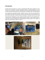
Our ECE 4760 final project is to build a microcontroller based smart medicine box. Our
medicine box is targeted on users who regularly take drugs or vitamin supplements or nurses
who take care of the older or patients. The medicine box is programmable that allows nurses
or users to specify the pill quantity to take and the serve time for each day. The smart medicine
box contains seven separate sub-boxes. Therefore, nurses or users can set information for
seven different pills. When the pill quantity and serve time has been set, the medicine box will
remind users or patients to take pills using sound and light. The specific number of pills needs
to be taken will be displayed by a seven segment led display placed on the corresponding box.
Compared with the traditional pillbox that requires users or nurses to load the box every day or
every week. Our smart medicine box would significantly release nurses or users’ burden on
frequently preloading pills for patients or users.
The finished product
2
I. High Level Design
1.1 Rationale and Inspiration
I am a international student, and during holidays I always bring some USA made medicines to
my grandparents back in China. I found they always have trouble remember the number of pills
they need to take from each of the medicine bottle because they couldn't read English. They
also complained to me that they sometimes forget to take to pills, and some medicines were
expired due to this reason. Therefore, the idea to make a smart pillbox that would help people
like my grandparents came to my mind. After I talked with my partner Jie, we broadened the
targeted users of our pillbox from just the older to people who regularly take pills. We also
thought nurses who take care of patients could also benefit from, since they also regularly
prepare pills for patients. After the targeted user being defined, we then defined the
specifications of our device based on the user needs. The device should be able to generate
loud sound so that even people with impaired hearing were able to hear it. The device should
demonstrate ease of use. Therefore, we decided to use a lcd and a keypad as the user
interface. In order to help user remember the number of pills they need to take, we also used
several seven segment LED displays to indicate the number of pills the user need to take.
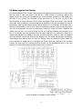
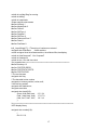
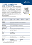
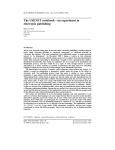
Based on theses specifications, we designed a high-level block diagram (figure below) to
demonstrate the overall design of our device.
s
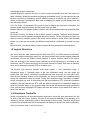
Figure 1: High-level block diagram
There are five major components for our device, including a pillbox containing seven separate
small boxes; a speaker module; a 3x4 keypad; an Atmel 1284p microcontroller; seven
segments LED display (7 units); and a 2x16 characters LCD screen. See figure [1] for the
schematic layout of our device.
3
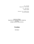
Functionality of each component:
Keypad: Keypad is used for the user or nurse to enter the specific time when the smart box
send “reminder” (displaying numbers and playing synthesized voice). It is also used for the user
to enter a number to command a specific pillbox to open on a specific day. (Say, open No.1
pillbox on Monday) The keypad is also used for stopping the music and led display when the
user has taken the pill.
LCD: The 2 line, 16 characters LCD screen is used to display the instruction information, the
number of pills need to be taken, and the current time and date.
Speaker Module: The speaker module is used to play the synthesized sound to remind the user
to take pill.
Pill boxes: Currently we decide to use a pillbox system containing 7 separate small pillboxes.
Each box has a seven segment led display placed on the box. For our pill system, the user can
store up to seven different types of pills, which can be stored in those seven small separate
boxes. He or she can also specify the different combinations of pillboxes to be open for each
day.
Microcontroller: One Atmel 1284p is used to execute all the commands mentioned above.
1.2 Logical Structure
Our device uses the state machine and real time clock (RTC) to provide real-time functionality.
This state machine determines which key has been pressed and provides keypad debounce
functionality. We use the 16MHz external oscillator to build a real time clock for the device.
Since the accuracy for the external crystal oscillator has a very high accuracy, and based on our
calculation, our RTC should only delay about several minutes in a week. Such error is tolerable,
since we not particularly used the RTC as an alarm clock.
The device's logic structure contains three major stages: 1. User initialization stage. 2.
Comparison stage. 3. Reminder stage. In the user initialization stage, the user enters the
current time, date and pill information (including amount and serve time for each type of pill).
After the user finishing entering all the information, the device will enter the comparison stage
unless the initialization button is pressed. During the comparison stage, the system compares
the pill information for each of the sub-box with the time counted by RTC. Once the information
entered by the user matches the RTC time, the system will jump out of comparison stage and
enter the reminder stage. In the reminder stage, the device will continuously play synthesized
voice, and the seven segments LED display will show the number of pills needs to be taken on
each of the sub-box.
1.3 Hardware Tradeoffs
Initially, we planned to use electrical magnetic solenoids to control the open and close of the lids
for each of the sub- boxes. However, the size of the solenoids available is not desirable to be
attached to the box, and shipping time for the solenoids is also too long. Therefore, we decided
to replace the solenoids with the seven segment led displays to achieve the same functionality,
which is to improve ease of use of the device.
4
Since we want to use one microcontroller to achieve all the functionality, tradeoffs need to be
made between saving pins and complicating the circuits. The 1284p microcontroller has 4 ports,
28 pins total. The LCD module needs 8 pins and the keypad needs 7 pins. The speaker module
needs a specific pin that is able to send PWM wave. Currently, we used a seven sub-boxes
system. If we directly use microcontroller to control all seven segment LED displays, the rest 2
ports would just be enough. However, if we need to add more features or add more sub-boxes,
this control mechanism of led displays is definitely inefficient. Therefore, we decided to use the
74LS138 3 to 8 decoder to control the switches (in this case are 2N3904 npn transistors) for
those LED displays. Using 3 to 8 decoder could save us 4 additional pins for future add on
features or sub-box. However, using 74LS138 would complicate the circuitry design. Current,
we built the external circuitry on breadboard due to the limitation of time. In the future,
customized PCB board can be used to simplify the circuitry as well as miniaturize the device
size.
1.4 Software Tradeoffs
When we displayed instructions on the LCD screen during initialization process, we previously
used the scheme developed in lab 2, that we showed the static texts and dynamic input at the
same time. However, due to the large amount of parameters in our system, we cannot use this
scheme anymore because that made the response of keypad extremely slow. Hence, we
developed a new scheme for the instruction texts display that will only show the static
characters once at the beginning of each status and this method achieved much better result for
the response speed of keypad.
1.5 Existing Products
We found several different pillbox products available in the market. The cheapest one was the
traditional pillbox, which contained seven boxes for seven different days of a week. Such pillbox
normally cost below $10. However, user had to load the pills to the boxes every week. Mixing
different pills in the same box would increase the risk of making mistakes. We also found
another type of pillbox, which had the sound reminder, and was able to remind the user to take
medicine at user specified time. However, the users still have to put different kinds of pills in the
same box, and reload the boxes every week. Additionally, It could only remind the user to take
pills once a day. The average costs of this type of pillbox were about $50, which was still
expensive than ours. Therefore, we think it was necessary to build a cheap and functional smart
pillbox that could bring more convenience for the user.
5
II. Software Design
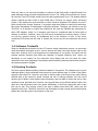
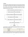
2.1 Overall Software design
We built a medicine box with an integrated software system running in the MCU. The
programming platform is AVRStudio4.0, and programming language is standard C and
WINAVR/GCC compiler. Generally, our software system can be divided into four parts, including
real time clock, user interface, LED control and sound generation. We could get information for
each medicine boxes from the user input and store the information in structure variables. The
real time clock would keep running once user finishes initialization. After all the information has
been entered. The system would enter comparison status. The comparison function would
detect if there were medicine should be taken at that time. When it finds medicine should be
taken, the audio will broadcast. After the user response to the system by pushing certain button,
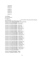
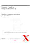
LEDs would indicate the amount of medicines for each box. Our system flow chart is as follow.
Software design flowchart
2.2 Data structure
The information of boxes will be stored in structs. For each box, we have a struct to store their
information. The struct contains four variables that indicate which day this medicine should be
taken, how many times per day it should be taken, the amount it should be taken each time
and a variable that using later by function that control the LEDs to indicate whether the LED of
this box should be light up.
2.3 Real time clock
The real time clock running in our system is implemented by using MCU 16-bits timer to
generate 1-second base. Firstly, we will open the compare match interrupt service routine, and
set the compare value to 249. Also, we scale the running frequency of timer1 to 1/64. Then, the
interval time between each interrupt routine is 0.001 second. We have a volatile variable to run
the clock function every 1000 interrupt routines. Then, in the clock function, it will run like a
6
clock. We have separated variable for two digits of seconds, minutes and one variable for hours.
We also have a variable for the weekdays. We do not store the year information because we
think it is unnecessary.
2.4 User interface
The user interface is made up of two main components, user input and system output. User
input method is keypad typing. System output methods are LCD display and LED digits display,
as well as audio broadcast.
LCD Control
The LCD library lcd_lib.c and lcd_lib.h are from Scienceprog.com. The functions in the library
already finish the fundamental tasks, such as showing characters on the screen, clean screen,
etc. We use these functions in the library to implement our own system.
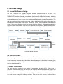
Keypad control
For the aim of obtaining the button that is pushed, we have a function for scanning the keypad. Firstly, set
high-4 bits of port to input and low-4 bits to output and get the value of the high-4 bits, then, inversely do
the same task and get the whole value of port. Then using this value we get to look up the button table to
find out which button we pushed. The state machine will execute every 25 milliseconds. In state detect,
we will judge which kind of button is pushed and do different things corresponding to the button, such as
run flag setting, input string updating and changing to next parameter input. In the done state, we will
update each variable in each box’s structure, and also, we will initialize some variable for the next round
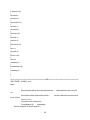
parameter input. Other states in the machine do not have specific function but debounce.
Keypad state machine flowchart
2.5 LED control
We use port A of microcontroller to transfer the data for seven segments LED and first three bits
of port B to transfer the control signal for the multiplexer. Hence, Our function related to LED
control is mainly controlling all this bits mentions above. Depends on the principle of persistence
of vision, we will show the data of each LED for a short time and then switch to the next one,
and doing this again and again to keep the LED lighting up. In our system, the function called
led() will execute this task according to the scheme mentions above. It will run every 4
milliseconds when the system running at triggered state.
7
2.6 Sound generation
For the sound generation, we use the method called differential, pulse-code modulation (DPCM)
that is linked in the ECE 4760 homepage. For the generation process, we have timer 0 to
working at PWM mode and timer 2 working at compare match status in order to simulate the
human speaking sound. We used the Matlab code to generate the sound data table of the
sound we need that is ‘Time to take medicine’.
III. Hardware Design
3.1 Microcontroller
The microcontroller used for the smart medicine box is the ATmega1284 mounted on a custom
PCB. We used port A for outputting numbers on led displays; port B for controlling the switches
and speaker module; port C for the LCD module; and Port D for keypad.
3.2 LCD module
The LCD module used in our project is a 16-characters, 2 lines Microtivity IM161 (with back
light). Considering its small size, ease of use and its yellow back, we think it is the best
candidate for our project. We found the yellow back light make it easier for the user to see the
characters displayed on it, even in the dark environment. Currently, we didn't have the back
light adjustment feature in our circuit. In the future, we will add this feature to our device so that
the user can dim the backlight during certain circumstances.
Pin 1 of the LCD module is connected to the ground. Pin2 is connected to the power supply of
the MCU. Pin 3 connects to the wiper of the 10k trimpot. Pin 4 is the register select, which is
connected to the C.0. Pin 5 is the data read/write, which is connected to C.1. Pin 6 is the enable
signal, which is connected to C.2. Pin 11 to pin 14 are the data bus, which are connected to
C.3-C.7. Pin15 and pin16 are the LED power and ground for the backlight. The optimal power
and current for the led backlight is 4.2V and 20mA.
lcd module used in our project
3.3 Keypad
The keypad we used for our device is a 3x4 12-button keypad, which is purchased from all
electronics. In the software design we will explain the key scan algorithm in detail.
8
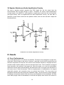
3.4 Seven segment led displays
We used Kingbright SC56-11EWA seven segment led displays for displaying the number of pills
the user need to take from each of the sub-box. SC56-11EWA is a common cathode led
display, which has seven pins corresponding to seven different segments on the display and
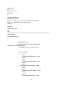
two pins as the ground. We designed circuits that allow us to use only 10 pins of the
microcontroller to control all seven units of these led displays (See figure below). The concept
behind this circuitry design is to use transistors as switches to turn the led displays on and off
sequentially. Such method can be realized with the use of a 3 to 8 decoder, which uses 3 pins
from the microcontroller to send 7 bits output to control the transistors. And the rest seven pins
from the microcontroller are used to send binary outputs to control the seven segments led
display one at a time. In our first prototype circuits, we used pnp transistors as switches, since
the 3 to 8 decoder can only generate one low output each time. We tested the circuits on a
breadboard with three led displays, and they all worked properly. However, after we soldered
the first prototype circuits with all seven led displays on it, we found the last three led displays
were always much dimmer than the rest led displays. After we talked with Bruce about our
circuit problem, he suggested us to redesign the circuits using npn transistors and inverters
instead. We then built our second prototype circuits on the breadboards due to the time
limitation. The second prototype worked properly after we tested it.
Seven Segment Led Display Control Circuitry
9
3.5 Speaker Modules and Audio Amplification Circuitry
We used a speaker module acquired from ECE digital lab, but the output from the
microcontroller was not large enough to drive it. Therefore, we used a sound amplification
circuitry based on a LM386 N-1 audio amplifier to amplify the sound from the microcontroller
(see figure below). After we implemented the audio amplification circuitry, we were able to
generate a much louder sound from the speaker module, and we were also able t adjust the
sound amplitude.
Schematic of the Audio Amplification Circuitry
IV. Results
4.1 Over Performance
The overall performance of our device was satisfied. The device was packaged in a paper box,
which was a little bit large for the device. However, it was able to cover all the messy wires and
electrical components, so that the user would not be distracted. Moreover, the paper box also
provided certain isolation ability to lower the electrical shock risks. The lcd module and keypad
were mounted on the surface of the paper box. When the power is on, the lcd would display
characters with the gentle yellow backlight, which allows the user to recognize the characters on
the screen even in dark environment. With the implementation of statemachine, the keypad
responded promptly and accurately when we pressed the buttons. The long press and
backspace features went well during the initialization stage. The seven units of seven segment
led displays were placed inside the box since they were embedded on the breadboard. We filled
some hard sponge under the breadboard, so that the led displays were close to the surface of
10
the paper box. The light intensity of led displays was satisfied, that the number displayed can be
easily recognized even when lab's fluorescent lamps were all on. During the test, we found that
the light intensity for some led displays was a little different than the others, but this would not
affect the users to recognize the numbers displayed. The speaker was able to produce clear
and loud synthesized sound when the comparison stage was triggered. When the "#" key was
pressed, the sound stopped, and we were able to see led displays show corresponding
numbers without any flicker.
4.2 User Evaluation (Usability)
Since our smart pillbox is intended to be used by the user who does not have any electrical
engineering background or is not able to operate a complicate system. Therefore, the user
evaluation is crucial for our project in terms of future improvements. We planned to do two
rounds of user evaluation; first round is focused on collecting feedbacks from people who have
strong learning ability and set the pill information by themselves. Second round of evaluation is
focused on collecting feedbacks from users who does not have strong learning ability and need
others' help to set the pill information.
We invited some of our friends as our first round users to try our device and give us some
feedbacks. Due to the limitation space for displaying characters on LCD, we were not able to
display the instructions on the lcd screen. Therefore, users needed to have some quick learning
on how to use the device. After around five minutes of learning, tester were able to set the real
time clock, and pill information for each of the medicine box with out any difficulty. In the future,
we would improve the user interface so that it can be more self-explanatory for the user to use.
It would also be helpful to create a user manual to help the user to use the device. Besides that,
our testers also thought the size of the paper box was a little big when compared with the actual
pill boxes mounted on the top. Our testers also concerned that the boxes were hard to open and
close. They also suggested that we should replace the pillboxes with larger ones. They also
thought it would be better to place the seven segments led displays on the surface of the paper
box, so that they could read the numbers displayed more easily. They also suggested that the
switch of the microcontroller should also be placed outside the box and marked; since the real
users might be have any knowledge about the circuitry. We created a table (see below) in order
to list all the suggestions and comments from our testers.
The priority level is rated based on how severe the problems would affect user to use the
pillbox. Since our second round testers are mainly the older, we decided to conduct the
evaluation during the winter break.
11
4.3 Safety
Our device is used to contain drugs, and it is defined as a class I device based on the definition
of the medical device by FDA(Link). Therefore, safety is one of the most important factor need
to be considered. We should identify all the possible risks and hazards before we build the
device. Validation of all the safety factors is also essential after we finish build the device. We
used the analysis structure (see figure below) described in Medical Device Use-Safety:
Incorporating Human Factors Engineering into Risk Managementoublished (Link) by FDA to
analyze the risks and hazards in our device.
In the identification of use-related hazard scenario stage, we identified the potential hazards
based on device use description. We found several potential hazards that would occur during
the use of the device (see table below).
Among all the hazards, we thought electrical shock and fire hazards should have the highest
priority, since these two hazards would not only cause malfunction of the device but also have
high risks of causing danger to the user. In order to mitigate the risks, we decided to cover the
12
entire circuits in an insulated box. We also planned to use high burning point material such as
metal or plastic for our box in order to lower the fire risk. However, due to the time limitation, we
had to choose a paper box for our current device, and we didn't cover the entire circuitry.
Therefore, we were still in the strategies implementation stage. However, for our future work, we
would still stick to the analysis structure to carefully manage the risks for our device.
V. Conclusions
5.1 Future Work
There are several aspects we need to work on our device in the future to meet the user needs.
Firstly, we should develop strategies and modify the device based on the user evaluation
results. This includes creating a user manual; choosing a larger lcd display; using a metal or
plastic box to cover the entire circuitry; placing the switch and led displays on the surface of the
box and using larger pill boxes.
We should also follow the risk analysis structure to analyze the potential risks and hazards as
well as develop strategies to mitigate the risks.
5.2 Standards
There is a standard in Code of Federal Regulation (CFD) that concentrates on devices design
related to food and drug (Title 21 - Food and Drugs). According to the standard, we choose the
material for medicine container and other components used in the box, such as led and
electromagnets. We will also design, built and code our device based on ANSI standard and
IEEE standard.
5.3 Intellectual Property Considerations
In this project, we wrote codes modified from the previous labs we did through the semester.
Most of the codes were written by us except the lcd_lib.c and lcd_lib.h licensed by GNU. We
designed our device from scratch, and did not reverse-engineer any past designs for similar
products.
5.4 Ethical Considerations
During the process of designing and building our device, we strictly adhered to the IEEE Code
of Ethics. Our device does not harm one's health or safety, and it won't endanger the
environment. While building the device, we used all the lab equipment according to the safety
requirements. While writing codes for our device, we didn't copy anyone's previous work. We
marked the license for the lcd_lib.h and lcd_lib.c, which were provided by GNU to drive our lcd
module.
In terms of the fifth item listed in the IEEE Code of Ethics, we believed we improved our
understanding of designing and building medical related device. And we believed our device
would help user to improve their life quality.
We also open for any criticism of our device in term of its possible technical problems. We
acknowledge all the helps and suggestions provided by Bruce (our instructor) and our TAs.
We are honest in collecting data from our testers, and we didn't falsify our verification and
validation process.
5.5 Legal Considerations
We searched on the webpage of US patent and trademark office for similar devices. We found
several patents related to the "pillbox or pill dispenser", but none of them was similar to ours in
13
terms of design (Reference ). Therefore, we think our device does not involve any legal and
patent issues.
14
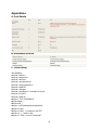
Appendices
A. Cost Details
B. Distribution of Work
C. Code Listing
//all headfiles;
#include <stdio.h>
#include <inttypes.h>
#include <avr/io.h>
#include <avr/interrupt.h>
#include <avr/pgmspace.h>
#include <stdlib.h>
#include <string.h>
#include <util/delay.h> // needed for lcd_lib
#include "lcd_lib.h"
#include <math.h>
#define F_CPU 16000000UL
#define begin {
#define end }
#define t1 20 //statemachine repeattime
#define t2 100//
#define t3 1000 // 1s base for the RTC
#define t4 1 // 4ms for led
#define t5 1000 //1 min for CompareF
15
//for audio
#define TableSize 2920 //refers to the following incl file
//Contains the packed 2-bit codes for syntehsis
//Generated by the program Make2code476.m
#include "DPCMAllDigits.h"
//reconstruction differentials
// PCMvalue[4] = {-78, -16, 16, 78};
volatile signed char PCMvalue[4] = {-20, -4, 4, 20};
volatile unsigned int outI, tableI; //indexes
volatile unsigned char cycle ;
//decode phase counter
volatile signed char out, lastout;
//output values
volatile unsigned char p1, p2, p3, p4;//hold 4 differentials
volatile unsigned char packed
;
//byte containing 4 2-bit values
int firstenter=1; // for the sound
//=====================================================
int countdisplay=0;
//Box information
struct box
{
int dayofweek[7];
int times2eat;
int amount2eat;
int flag;
};
struct box box[7];
int boxnum=0;
// RTC PARAMETERS
int second1,second2,minute1,minute2,hour,weekdays;
second1=0;
second2=0;
minute1=9;
minute2=5;
hour=7;
weekdays=1;//1 represents Monday and so on
//fake time====
second11=0;
second22=0;
minute11=0;
minute22=0;
hour1=0;
16
volatile int runflag;//flag for running
volatile int hitflag;
volatile int responseb;
//State machine state names
#define NoPush 1
#define MaybePush 2
#define Detect 3
#define StillType 4
#define Release 5
#define StillTerm 6
#define DebounceTerm 7
#define Done 8
#define RunState 9
int8_t InputString[17]; // The string of numbers we entered
unsigned char PushState;
//state machine
volatile unsigned char timeofstatemachine, timeofbuttonRes,timedisplay;
volatile int timeCompareF; //for ComparaF
volatile int timesound;
volatile int trtc; //for real time clock
//for keypad scan============================================
#define maxkeys 12
#define PORTDIR DDRD
#define PORTDATA PORTD
#define PORTIN PIND
// The raw keyscan
unsigned char key;
// The decoded button number
unsigned int butnum,position,i,value,multi;
// the last key pushed
unsigned char lastbutnum;
//key pad scan table
unsigned char keytbl[16]=
{0xee, 0xde,0xbe,0xed, //{1 2 3 4
0xdd, 0xbd,0xeb, 0xdb, // 5 6 7 8
0xbb, 0xe7, 0xd7, 0xb7, //9 * 0 #
};
//============================================================
//LED display library
unsigned char number[10]=
{
0b1111110,
17
0b1001000,
0b0111101,
0b1101101,
0b1001011,
0b1100111,
0b1110111,
0b1001100,
0b1111111,
0b1101111
};
//LCD display
int8_t lcd_buffer[17];
int Pointer=0;
int OldPointer=8;
//for the position of the pointer when setting the
days of the week at the starting of the system
const int8_t LCD_initialize[] PROGMEM = "LCD Initialized\0";
const int8_t LCD_p1[] PROGMEM = "m t w t f s s";
const int8_t LCD_p2[] PROGMEM = "Set minutes: ";
const int8_t LCD_p3[] PROGMEM = "Set Hours: ";
const int8_t LCD_p4[] PROGMEM = "BOX1 Date: ";
const int8_t LCD_p5[] PROGMEM = "BOX1 Time: ";
const int8_t LCD_p6[] PROGMEM = "BOX1 Amount:";
const int8_t LCD_p7[] PROGMEM = "BOX2 Date: ";
const int8_t LCD_p8[] PROGMEM = "BOX2 Time: ";
const int8_t LCD_p9[] PROGMEM = "BOX2 Amount: ";
const int8_t LCD_p10[] PROGMEM = "BOX3 Date: ";
const int8_t LCD_p11[] PROGMEM = "BOX3 Time: ";
const int8_t LCD_p12[] PROGMEM = "BOX3 Amount: ";
const int8_t LCD_p13[] PROGMEM = "BOX4 Date: ";
const int8_t LCD_p14[] PROGMEM = "BOX4 Time: ";
const int8_t LCD_p15[] PROGMEM = "BOX4 Amount: ";
const int8_t LCD_p16[] PROGMEM = "BOX5 Date: ";
const int8_t LCD_p17[] PROGMEM = "BOX5 Time: ";
const int8_t LCD_p18[] PROGMEM = "BOX5 Amount: ";
const int8_t LCD_p19[] PROGMEM = "BOX6 Date: ";
const int8_t LCD_p20[] PROGMEM = "BOX6 Time: ";
const int8_t LCD_p21[] PROGMEM = "BOX6 Amount: ";
const int8_t LCD_p22[] PROGMEM = "BOX7 Date: ";
const int8_t LCD_p23[] PROGMEM = "BOX7 Time: ";
const int8_t LCD_p24[] PROGMEM = "BOX7 Amount: ";
const int8_t LCD_p25[] PROGMEM = "Time to eat";
const int8_t LCD_space[] PROGMEM = " ";
const int8_t Monday[] PROGMEM = "MON";
const int8_t Tuesday[] PROGMEM = "TUS";
18
const int8_t Wednesday[] PROGMEM = "WED";
const int8_t Thursday[] PROGMEM = "THU";
const int8_t Friday[] PROGMEM = "FRI";
const int8_t Saturday[] PROGMEM = "SAT";
const int8_t Sunday[] PROGMEM = "SUN";
unsigned int paranum=0; //For parameter input and LCD showing staff
unsigned int lock=0;
//keypad scanf function===================================
void scanfkeypad()
begin
//get lower nibble
PORTDIR = 0x0f;
PORTDATA = 0xf0;
_delay_us(5);
key = PORTIN;
//get upper nibble
PORTDIR = 0xf0;
PORTDATA = 0x0f;
_delay_us(5);
key = key | PORTIN;
butnum=0;
//find matching keycode in keytbl
if (key != 0xff)
begin
for (butnum=0; butnum<maxkeys; butnum++)
begin
if (keytbl[butnum]==key)
break; // break when keyscan finds the pressed key
end
if (butnum==maxkeys)
butnum=0; // detect more than one key is pushed
else butnum++; // adjust to 1-16
end // end the search
else butnum=0;
end //end keyscan
//==============real time clock =================
void rtc()
{
trtc=t3; //reset t3
second1++;
19
if (second1>9)
{
second2++;
second1=0;
}
if(second2==6)
{
minute1++;
second2=0;
}
if(minute1>9)
{
minute2++;
minute1=0;
}
if(minute2==6)
{
hour++;
minute2=0;
}
if(hour==24)
{
hour=0;
weekdays++;
}
if(weekdays==8)
{
weekdays=1;
}
}
//====================================ISR================================
ISR (TIMER1_COMPA_vect)
begin
if(timeofstatemachine>0)timeofstatemachine--;
//statemachine start every 25
ms
if(timeofbuttonRes>0)timeofbuttonRes--;
every 100ms
if (trtc>0) trtc--;
if (timesound>0) timesound--;
if (timedisplay>0)
timedisplay--;
if(timeCompareF>0) timeCompareF--;
20
//screen responds function excute
end
//generate waveform at 7812 scamples/sec
ISR (TIMER2_OVF_vect)
begin
//compute next sample
cycle = outI & 3; // outI modulo 4
if (cycle==0)
//do we need to unpack more data?
begin
if (tableI<TableSize) //end of stored wave?
begin
//unpack a table entry into 2-bit indexs
// pgm_read_byte (address_short)
packed = pgm_read_byte(&DPCMAllDigits[tableI]) ;
//packed = DPCMAllDigits[tableI];
p1 = (packed>>6) & 3 ;
p2 = (packed>>4) & 3 ;
p3 = (packed>>2) & 3 ;
p4 = (packed & 3);
tableI++ ;
end //end unpack table entry
//compute the output and send to PWM
out = lastout + PCMvalue[p1] - (lastout>>3) ;
end
else if (cycle==1) //don't need to unpack yet--just ouput
out = lastout + PCMvalue[p2] - (lastout>>3) ;
else if (cycle==2)
out = lastout + PCMvalue[p3] - (lastout>>3) ;
else if (cycle==3)
out = lastout + PCMvalue[p4] - (lastout>>3) ;
//update outputs
OCR0A = out + 128;
lastout = out;
outI++;
//at end, turn off TCCRO
if (tableI==TableSize) TCCR0B = 0;
end //ISR
//****************************************************************************************************
// LCD setup
void init_lcd(void)
begin
LCDinit();
//initialize the display
21
LCDcursorOFF();
LCDclr();
//clear the display
LCDGotoXY(0,0);
CopyStringtoLCD(LCD_initialize, 0, 0); // display initialize to test the function of LCD
end
//===========================================================
//Set it all up
void initialize(void)
begin
init_lcd();
//for audio==================================================
DDRB=(1<<PORTB3);
// turn on pwm with period= 256 cycles
// (62,500 samples/sec) in fast PWM mode.
// BUT OCR0A update is done using timer2 at 7800/sec
// timer 0 runs at full rate set in MAIN loop; TCCR0B = 1 ;
// turn on fast PWM and OC0A output
// 16 microsec per PWM cycle sample time
TCCR0A = (1<<COM0A0) | (1<<COM0A1) | (1<<WGM00) | (1<<WGM01) ;
OCR0A = 128 ; // set PWM to half full scale
// turn on timer2 set to overflow at 7812 Hz
// (prescaler set to divide by 8)
TCCR2B = 2;
// turn on overflow interrupt
TIMSK2 = (1<<TOIE2);
///============================================================
DDRA=0xff; //set A as the output of LED number
DDRB=0x0F;
//B.0-B2 as output for choosing LED
//set up timer 1 for 1 mSec timebase for fast pwm mode and full speed
TIMSK1 = 2;
//turn on timer 1 cmp match ISR
OCR1A = 249;
//set the compare reg to 250 time ticks
//TCCR1A = 0b00000010; // turn on clear-on-match
TCCR1B = 0b00001011;
// clock prescalar to 64 and turn on CTC
//initialize time variables
timeofstatemachine=t1;
timeofbuttonRes=t2;
trtc=t3;
timedisplay=t4;
timeCompareF=t5;
//set flag
runflag=0;
hitflag=0;
22
responseb=0;
int i;
for(int i=0;i<7;i++){
box[i].flag=0;
}
//init the state machine
PushState = NoPush;
position = 0; // the count for the input number to the string buffer
multi = 1; // used for converting char to integer
value = 0;
paranum=1;
//crank up the ISRs
sei() ;
end
//===============================================================
//show the time
void showtime(int pos)
{
LCDGotoXY(0,pos);
sprintf(lcd_buffer, "%d:%d%d:%d%d",hour,
minute2,minute1,second2,second1);
LCDstring(lcd_buffer, strlen(lcd_buffer));
switch (weekdays)
{
case 1:
CopyStringtoLCD(Monday, 11,pos);
break;
case 2:
CopyStringtoLCD(Tuesday, 11,pos);
break;
case 3:
CopyStringtoLCD(Wednesday, 11,pos);
break;
case 4:
CopyStringtoLCD(Thursday, 11,pos);
break;
case 5:
CopyStringtoLCD(Friday, 11,pos);
23
break;
case 6:
CopyStringtoLCD(Saturday, 11,pos);
break;
case 7:
CopyStringtoLCD(Sunday, 11,pos);
break;
}
}
//=====================LDE DISPALY===============================
void led()
begin
timedisplay=t4;
if((countdisplay==0)&&(box[0].flag==1))
{
PORTB = (0<<PINB0)|(0<<PINB1)|(0<<PINB2);
PORTA=number[box[0].amount2eat];
}
if((countdisplay==1)&&(box[1].flag==1))
{
PORTB = (1<<PINB0)|(0<<PINB1)|(0<<PINB2);
PORTA=number[box[1].amount2eat];
}
if((countdisplay==2)&&(box[2].flag==1))
{
PORTB=(0<<PINB0)|(1<<PINB1)|(0<<PINB2);
PORTA=number[box[2].amount2eat];
}
if((countdisplay==3)&&(box[3].flag==1))
{
PORTB=(1<<PINB0)|(1<<PINB1)|(0<<PINB2);
PORTA=number[box[3].amount2eat];
}
if((countdisplay==4)&&(box[4].flag==1))
{
PORTB=(0<<PINB0)|(0<<PINB1)|(1<<PINB2);
PORTA=number[box[4].amount2eat];
}
if((countdisplay==5)&&(box[5].flag==1))
{
PORTB=(1<<PINB0)|(0<<PINB1)|(1<<PINB2);
PORTA=number[box[5].amount2eat];
}
if((countdisplay==6)&&(box[6].flag==1))
24
{
PORTB=(0<<PINB0)|(1<<PINB1)|(1<<PINB2);
PORTA=number[box[6].amount2eat];
}
countdisplay++;
if(countdisplay>6) countdisplay=0;
end
//=====================COMPARE FUNcTION===============================
void CompareF()
begin
timeCompareF=t5;
int i;
int j;
for(i=0;i<7;i++)
{
for(j=0;j<7;j++)
{
if(box[i].dayofweek[j]==weekdays&&minute1==0&&minute2==0&&second1==0&&second2==0)
{
LCDGotoXY(12,1);
// location for the pointer
sprintf(lcd_buffer, "%d",box[0].dayofweek[0]);
LCDstring(lcd_buffer, strlen(lcd_buffer));
switch (hour)
{
case 8:
if(box[i].times2eat==2||box[i].times2eat==3)
box[i].flag=1;
hitflag=1;
lock=0;
//send messge to turn on led
break;
case 12:
if (box[i].times2eat==1||box[i].times2eat==3)
box[i].flag=1;
hitflag=1;
lock=0;
break;
case 18:
25
if (box[i].times2eat==2||box[i].times2eat==3)
box[i].flag=1;
hitflag=1;
lock=0;
break;
}//switch
} //if
}//for
}
scanfkeypad();
if(butnum==10)
{
PushState=NoPush;
paranum=4;
lock=0;
runflag=0;
boxnum=0;
}
if(butnum==12)
{
hitflag=0;
LCDclr();
responseb=0;
PORTA=0b00000000;
for(i=0;i<7;i++)box[i].flag=0;
}
end
//==================================================================
void StaticString()
begin
switch(paranum)
begin
26
case 0:
if(lock==0)
{
LCDclr();
showtime(0);
lock=1;
}
break;
case 1:
if(lock==0)
{
LCDclr();
CopyStringtoLCD(LCD_p1,0,0); // print out m t w...
lock=1;
}
break;
case 2:
if (lock==0)
{
LCDclr();
CopyStringtoLCD(LCD_p2,0,0);
lock=1;
}
break;
case 3:
if (lock==0)
{
LCDclr();
CopyStringtoLCD(LCD_p3,0,0);
lock=1;
}
break;
case 4:
if (lock==0)
{
LCDclr();
CopyStringtoLCD(LCD_p4,0,0);
lock=1;
}
27
break;
case 5:
if(lock==0)
{
LCDclr();
CopyStringtoLCD(LCD_p5,0,0);
lock=1;
}
break;
case 6:
if (lock==0)
{
LCDclr();
CopyStringtoLCD(LCD_p6,0,0);
lock=1;
}
break;
case 7:
if (lock==0)
{
LCDclr();
CopyStringtoLCD(LCD_p7,0,0);
lock=1;
}
break;
case 8:
if (lock==0)
{
LCDclr();
CopyStringtoLCD(LCD_p8,0,0);
lock=1;
}
break;
case 9:
if (lock==0)
{
LCDclr();
CopyStringtoLCD(LCD_p9,0,0);
lock=1;
}
break;
case 10:
if (lock==0)
{
28
LCDclr();
CopyStringtoLCD(LCD_p10,0,0);
lock=1;
}
break;
case 11:
if (lock==0)
{
LCDclr();
CopyStringtoLCD(LCD_p11,0,0);
lock=1;
}
break;
case 12:
if (lock==0)
{
LCDclr();
CopyStringtoLCD(LCD_p12,0,0);
lock=1;
}
break;
case 13:
if (lock==0)
{
LCDclr();
CopyStringtoLCD(LCD_p13,0,0);
lock=1;
}
break;
case 14:
if (lock==0)
{
LCDclr();
CopyStringtoLCD(LCD_p14,0,0);
lock=1;
}
break;
case 15:
if (lock==0)
{
LCDclr();
CopyStringtoLCD(LCD_p15,0,0);
lock=1;
}
29
break;
case 16:
if (lock==0)
{
LCDclr();
CopyStringtoLCD(LCD_p16,0,0);
lock=1;
}
break;
case 17:
if (lock==0)
{
LCDclr();
CopyStringtoLCD(LCD_p17,0,0);
lock=1;
}
break;
case 18:
if (lock==0)
{
LCDclr();
CopyStringtoLCD(LCD_p18,0,0);
lock=1;
}
break;
case 19:
if (lock==0)
{
LCDclr();
CopyStringtoLCD(LCD_p19,0,0);
lock=1;
}
break;
case 20:
if (lock==0)
{
LCDclr();
CopyStringtoLCD(LCD_p20,0,0);
lock=1;
}
break;
case 21:
if (lock==0)
30
{
LCDclr();
CopyStringtoLCD(LCD_p21,0,0);
lock=1;
}
break;
case 22:
if (lock==0)
{
LCDclr();
CopyStringtoLCD(LCD_p22,0,0);
lock=1;
}
break;
case 23:
if (lock==0)
{
LCDclr();
CopyStringtoLCD(LCD_p23,0,0);
lock=1;
}
break;
case 24:
if (lock==0)
{
LCDclr();
CopyStringtoLCD(LCD_p24,0,0);
lock=1;
}
break;
case 25:
if(hitflag==0)
showtime(0);
else if(lock==0)
{
LCDclr();
CopyStringtoLCD(LCD_p25,0,0);
lock=1;
}
break;
end // switch
end
31
//==================================================================
void buttonResponse() // refresh lcd every 100ms and
begin
timeofbuttonRes=t2;
switch(paranum)
{
case 0:
showtime(0);
break;
case 1:
//CopyStringtoLCD(LCD_p1,0,0); // print out m t w...
LCDGotoXY(Pointer,1);
// location for the pointer
sprintf(lcd_buffer, "%c",94);
LCDstring(lcd_buffer, strlen(lcd_buffer)); // display the new pointer
LCDGotoXY(OldPointer,1);
sprintf(lcd_buffer, "%s"," ");
LCDstring(lcd_buffer, strlen(lcd_buffer)); // erase the old pointer
break;
case 2:
showtime(1);
break;
case 3:
showtime(1);
break;
case 4: // box1 date
LCDGotoXY(0,1);
LCDstring(InputString, strlen(InputString));
break;
case 5: ///box1 time
LCDGotoXY(0,1);
LCDstring(InputString, strlen(InputString));
break;
case 6:
LCDGotoXY(0,1);
LCDstring(InputString, strlen(InputString));
break;
case 7:
LCDGotoXY(0,1);
32
LCDstring(InputString, strlen(InputString));
break;
case 8:
LCDGotoXY(0,1);
LCDstring(InputString, strlen(InputString));
break;
case 9:
LCDGotoXY(0,1);
LCDstring(InputString, strlen(InputString));
break;
case 10:
LCDGotoXY(0,1);
LCDstring(InputString, strlen(InputString));
break;
case 11:
LCDGotoXY(0,1);
LCDstring(InputString, strlen(InputString));
break;
case 12:
LCDGotoXY(0,1);
LCDstring(InputString, strlen(InputString));
break;
case 13:
LCDGotoXY(0,1);
LCDstring(InputString, strlen(InputString));
break;
case 14:
LCDGotoXY(0,1);
LCDstring(InputString, strlen(InputString));
break;
case 15:
LCDGotoXY(0,1);
LCDstring(InputString, strlen(InputString));
break;
case 16:
33
LCDGotoXY(0,1);
LCDstring(InputString, strlen(InputString));
break;
case 17:
LCDGotoXY(0,1);
LCDstring(InputString, strlen(InputString));
break;
case 18:
LCDGotoXY(0,1);
LCDstring(InputString, strlen(InputString));
break;
case 19:
LCDGotoXY(0,1);
LCDstring(InputString, strlen(InputString));
break;
case 20:
LCDGotoXY(0,1);
LCDstring(InputString, strlen(InputString));
break;
case 21:
LCDGotoXY(0,1);
LCDstring(InputString, strlen(InputString));
break;
case 22:
LCDGotoXY(0,1);
LCDstring(InputString, strlen(InputString));
break;
case 23:
LCDGotoXY(0,1);
LCDstring(InputString, strlen(InputString));
break;
case 24:
LCDGotoXY(0,1);
LCDstring(InputString, strlen(InputString));
break;
34
}
end
//=================================================================
void statemachine(void)
begin
timeofstatemachine=t1; //reset the task timer
switch (PushState)
begin
case NoPush:
scanfkeypad(); // keypad scan
if (butnum!=0)
begin
PushState=MaybePush; // goes to maybepush when butnum not 0
lastbutnum=butnum;
end
else
PushState=NoPush;
break;
case MaybePush:
scanfkeypad();
if (butnum==lastbutnum)
begin
PushState=Detect; //when button is still pushed go to detect
whether "enter" key is being pressed
end
else
PushState=NoPush;
break;
case Detect:
if(butnum==12)//enter key
{ PushState = StillTerm;
}
if (PushState == StillTerm) break;
//set the system weekdays
if(paranum==1)
{
OldPointer=Pointer;
if (butnum==8)Pointer=Pointer-2;
if(butnum==9)Pointer=Pointer+2;
if(Pointer<0)Pointer=12;
if(Pointer>12)Pointer=0;
35
PushState = StillType;
}
//set the system time
if(paranum>1&¶num<4)
{
PushState = NoPush;
switch(paranum)
{
case 2:
if(butnum==5)//first up
minute2++;
if(minute2>5)
minute2=0;
if(butnum==8)//first down
minute2--;
if(minute2<0)
minute2=9;
if(butnum==6)//second up
minute1++;
if(minute1>9)
minute1=0;
if(butnum==9)//second down
minute1--;
if(minute1<0)
minute1=5;
break;
case 3:
if(butnum==5)//first up
hour++;
if(hour>24)
hour=0;
if(butnum==8)//first down
hour--;
if(hour<0)
hour=24;
break;
}
}
//Box information
if(paranum>=4)
{
PushState = StillType;
if (butnum!=10&&butnum!=12)
36
{
InputString[position] = butnum+'0';
position++;
}
if( butnum==10)
{
position--;
InputString[position]=' ';
}
}
break;
case StillType:
scanfkeypad();
if (butnum == lastbutnum)
begin
PushState = StillType;// the button is still pressed
end
else
PushState = Release; // the button does released
break;
case Release:
scanfkeypad();
if (butnum == lastbutnum)
PushState = StillType; // to remove debounce
else
PushState = NoPush; //go to the first state and press a new character
break;
case StillTerm:
scanfkeypad();
if (butnum == lastbutnum)
PushState = StillTerm; // it's the debounce step, so if the button is
still pressetd it goes to itself
else
PushState = DebounceTerm;
break;
case DebounceTerm:
scanfkeypad();
if (butnum == lastbutnum)
PushState = StillTerm; // if it's still pressed go to the last state to
scan again
else
PushState = Done;
break;
37
case Done:
lock=0; //reset lock ===========
if(paranum==1) weekdays=Pointer/2+1;
if(paranum>=4)
{
for(int k=0;k<position-1;k++)//just translate the input string into numberial
value
begin
multi=multi*10;
end
for (i = 0;i < position ;i++)
begin
value = value+((int)(InputString[i] - '0') * multi);
multi = multi / 10;
end
int sw=paranum-3-boxnum*3;
switch (sw)
{
case 1:
for(i = 0;i < position ;i++)
box[boxnum].dayofweek[i]=InputString[i]-'0';
break;
case 2:
box[boxnum].times2eat=value;
break;
case 3:
box[boxnum].amount2eat=value;
boxnum++;
break;
}
for(int i=0;i<position;i++)//clear the buffer for the input string
InputString[i]=' ';
position=0;//clear variables for the next parameter input
multi=1;
value=0;
38
}
paranum++;
if(paranum>=25)
{
runflag=1;
LCDclr();
}
else
PushState=NoPush;
break;
end
end
//main==============================================================
int main(void)
begin
initialize();
LCDclr();
while(1)
begin
if(trtc==0) rtc();
StaticString();
if(runflag==0)
{
if(timeofbuttonRes==0) buttonResponse();// excute buttonResonse every 100 ms
if(timeofstatemachine==0) statemachine();
}
else
{
if(timeCompareF==0) CompareF();
}
if(hitflag==1)
{
//init the output indexes
if(responseb==0)
{
switch (firstenter)
39
{
case 1:
outI = 0;
tableI = 0;
//init the ouptut value
lastout = 0;
// turn on PWM
TCCR0B = 1;
firstenter=2;
break;
case 2:
//wait until the speech is done then
//time delay the next utterance.
if(TCCR0B==0)
{_delay_ms(1000);
firstenter=1;
}
break;
}// switch
} // if
else
{
if(timedisplay==0) led();
}
scanfkeypad();
if(butnum==11)
{
responseb=1;
}
}
end
end
40
41