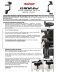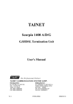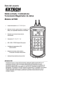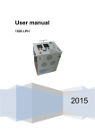
1
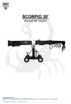
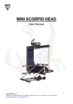
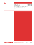
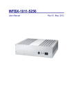
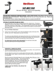
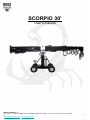
SCORPIO 30’ User’s manual SERVICEVISION BIS SL Ríos Rosas, 20 · 08940 CORNELLÀ DE LLOBREGAT (Barcelona) Spain · Tel. 34 93 223 86 30 · Fax 34 93 223 86 31 [email protected] · www.servicevision.es 1 INDEX 1-. Description…………………………………………………………………………………3 2-. The Electronic Control Box…………………………………………..………………...5 2-.1 Functions………………………………………………………..……………….….11 2.1.1 Start up Prodecure …………………………………………………….…...….11 2.1.2 Settings “Settings”………………………..…………………………………….15 2.1.3 Límits“Limits”………………………………………………….……………..….23 2.1.4 The Arc Compensator “Arc Comp”……………………………….……….….24 2.1.5 Dynamic Counter Weight System Generator“CWE Gen”……………....….25 2.1.6 Motion Generator“MOTION GENERATOR”……………………………..…..25 2.1.7 Sequential Limits “STOP SEQUENCE”…………………….……….………..28 2.2 Hand command…………………………………………………….………………..31 3-. Leveling Head……………………………………..………………….……….…...... ..33 SERVICEVISION BIS SL Ríos Rosas, 20 · 08940 CORNELLÀ DE LLOBREGAT (Barcelona) Spain · Tel. 34 93 223 86 30 · Fax 34 93 223 86 31 [email protected] · www.servicevision.es 2 1-. Description. The SCORPIO 30´ is a 9 meter/ 30 foot telescopic crane. It has a telescopic arm range of 7 meters/ 21 foot. The crane arm is made of aluminium. It has 4 steel guides and two independent cables per tube. This provides smoother and quieter movement. It has an electronic box which gives enough power to run the crane with a maximum controlled speed of “1,2m/s”. Added features are: adjustable damping, electronic arm limits, an arc compensator, a motion generator, output encoder information, crane arm length and height, a stop sequence program and other information on a display screen. It has a levelling head which is mounted at the end of the telescopic arm. The levelling head maintains the horizon in all positions for the Remote Camera Head. Techincal especifications. - Weight: 840 kg. / 1851,88 lb. - Max. weight: 1500 kg./ 3306,93 lb. - Max payload underslung: 70 kg / 154.3 lb. - Max.payload overslung: 30kg. / 66.1 lb - Max speed:1,2 m/s - Arm lenght: 9m. / 30 ft. - Telescopic range: 7m. / 21 ft. SERVICEVISION BIS SL Ríos Rosas, 20 · 08940 CORNELLÀ DE LLOBREGAT (Barcelona) Spain · Tel. 34 93 223 86 30 · Fax 34 93 223 86 31 [email protected] · www.servicevision.es 3 • Crane weight : 840 kg ( 1851.88lb ) • Max. weight: 1500kg ( 3306.93lb ) • Max. Payload in underslung: 70kg ( 154.3lb ) • Max. Payload in overslung: 30kg ( 66.16lb ) SERVICEVISION BIS SL Ríos Rosas, 20 · 08940 CORNELLÀ DE LLOBREGAT (Barcelona) Spain · Tel. 34 93 223 86 30 · Fax 34 93 223 86 31 [email protected] · www.servicevision.es 4 2-. The Electronic Control Box The SCORPIO 30´ is controlled by an Electronic Control Box. The Electronic Control Box controls and drives the crane´s motor which in turn moves the telescopic crane arm. It also controls other special features which puts the SCORPIO 30´ apart from the other telescopic cranes. It serves as the Central Control Unit for the Leveling Head and the Dynamic Counter Weight System. It reads all the encoder information from all the cranes axes so that it can, later, be used by external systems. The Electronic Control Box has a screen which is the “interface” between the user and the SCORPIO 30´. Start button Power In swich Power In display Stop emergency Fan Driver’s LED Servo’s LED Display Selection’s button Fan SERVICEVISION BIS SL Ríos Rosas, 20 · 08940 CORNELLÀ DE LLOBREGAT (Barcelona) Spain · Tel. 34 93 223 86 30 · Fax 34 93 223 86 31 [email protected] · www.servicevision.es 5 Motor’s connector Encoder output’s connector - D connector 25 female DB-25S-A191-A1977 Hand command’s connector - NEUTRIK 7pins panel female NC7FP1 SERVICEVISION BIS SL Ríos Rosas, 20 · 08940 CORNELLÀ DE LLOBREGAT (Barcelona) Spain · Tel. 34 93 223 86 30 · Fax 34 93 223 86 31 [email protected] · www.servicevision.es 6 Encoder output’s connector -D connector 25 female DB-25S-A191-A1977 13 B- ARM Brown 25 B- TRACK CRANE Brown 12 B+ ARM White 24 B+ TRACK CRANE White 11 A- ARM Blue 23 A- TRACK CRANE Blue 10 A+ ARM Green 22 A+ TRACK CRANE Green 9– 21 B- TILT CRANE Brown 8– 20 B+ TILT CRANE White 7 GND Green 19 A- TILT CRANE Blue 6– 18 A+ TILT CRANE Green 5– 17 B- PAN CRANE Orange 4– 16 B+ PAN CRANE Yellow 3 RX Brown 15 A- PAN CRANE Black 2 TX Red 14 A+ PAN CRANE Red 1– 26 – 27– • Hand command’s connector • NEUTRIK 7pins panel female NC7FP1 1 Red (VCC +5) 2 Black (GND) 3 Blue (COMMAND) 4 Yellow (SPEED) 5 Orange (GREEN SWITCH - GND) 6 Grey (GND) 7 Purple (RELAY RED SWITCH) SERVICEVISION BIS SL Ríos Rosas, 20 · 08940 CORNELLÀ DE LLOBREGAT (Barcelona) Spain · Tel. 34 93 223 86 30 · Fax 34 93 223 86 31 [email protected] · www.servicevision.es 7 AC Output Scoprio Head for power supply - BURNDY 4 pins female panel UT100-104ST 12V Output for monitor -NEUTRIK 4 pins female panel NC4 FP1 Dynamic Counterweight System Cable -BRUNDY 8 pins female panel UTGO 128S EB –001-2 15A Connector AC (110V a 240V 16A) Leveling Head Cable -BRUNDY 8 pins female panel UTGO 128S Input Tilt encoder - LEMO 10 pin female panel EGG -2B.310.CYM Input Pan encoder - LEMO 10 pin female panel EGG -2B.310.CYM Input wheel track encoder - LEMO 10 pin female panel EGG -2B.310.CYM SERVICEVISION BIS SL Ríos Rosas, 20 · 08940 CORNELLÀ DE LLOBREGAT (Barcelona) Spain · Tel. 34 93 223 86 30 · Fax 34 93 223 86 31 [email protected] · www.servicevision.es 8 • AC Output Scoprio Head for power supply -BURNDY 4 pins female panel UT100-104ST 1 Blue (VCC 220V) 2 3 Yellow (GND 220V) 4 Yellow – Green (GROUND) • 12V Output for monitor -NEUTRIK 4 pins female panel NC4 FP1 1 Black (GND) 2 3 4 Red (VCC +12V) • Dynamic Counterweight System Cable -BRUNDY 8 pins female panel UTGO 128S EB –001-2 1 Red (CVV +28V) 2 Black (GND) 3 Green (LEVEL A1+ OUT) 4 Blue (LEVEL A1 - OUT) 5 Grey (485 -) 6 Blue (485 +) 7 White (LEVEL B1 + OUT) 8 Brown (LEVEL B1 - OUT) • Leveling Head Cable -BRUNDY 8 pins female panel UTGO 128S 1 Red (CVV +28V) 2 Black (GND) 3 Green (LEVEL A1+ OUT) 4 Blue (LEVEL A1 - OUT) 5 Grey (485 -) 6 Blue (485 +) 7 White (LEVEL B1 + OUT) 8 Brown (LEVEL B1 - OUT) SERVICEVISION BIS SL Ríos Rosas, 20 · 08940 CORNELLÀ DE LLOBREGAT (Barcelona) Spain · Tel. 34 93 223 86 30 · Fax 34 93 223 86 31 [email protected] · www.servicevision.es 9 • Input Tilt encoder -LEMO 10 pin female panel EGG -2B.310.CYM 1 Red (VCC) 2 Black (GND) 3 Green (ENC A+) 4 Blue (ENC A-) 5 White (ENC B+) 6 Brown (ENC B-) 78910 - • Input Pan encoder -LEMO 10 pin Female panel EGG -2B.310.CYM 1 Red (VCC) 2 Black (GND) 3 Green (ENC A+) 4 Blue (ENC A-) 5 White (ENC B+) 6 Brown (ENC B-) 78910 • Input wheel track encoder -LEMO 10 pin Female panel EGG -2B.310.CYM 1 Red (VCC) 2 Black (GND) 3 Green (ENC A+) 4 Blue (ENC A-) 5 White (ENC B+) 6 Brown (ENC B-) 78910 SERVICEVISION BIS SL Ríos Rosas, 20 · 08940 CORNELLÀ DE LLOBREGAT (Barcelona) Spain · Tel. 34 93 223 86 30 · Fax 34 93 223 86 31 [email protected] · www.servicevision.es 10 2.1 Functions 2.1.1 Start up Procedure Before the crane can be switched on the correct voltage, depending on the setting of the Voltage Selector Switch 110/220V, must appear on the volt meter “POWER IN”. Once the voltage has reached it´s peak the “START” button can be pressed. After pressing the START button screen “1” will appear. It shows us that the system is trying to connect with the Motor and the Leveling Head axes. Pantalla 1 If the Central Control Unit does not find one or both of these axes screen “2” will automatically appear and show us that there is a communication problem. Pantalla 2 SERVICEVISION BIS SL Ríos Rosas, 20 · 08940 CORNELLÀ DE LLOBREGAT (Barcelona) Spain · Tel. 34 93 223 86 30 · Fax 34 93 223 86 31 [email protected] · www.servicevision.es 11 If the Central Control Unit finds all axes screen “3” will automatically appear and show us that the Leveling Head is searching the “0” or real horizon automatically. Pantalla 3 Once the horizon has been reached screen “4” will automatically appear. While the crane is switched on the Leveling Head will maintain this level. If we have not selected [Search Level] YES the system will pass straight on to screen “4”. The level at which the Leveling Head is will be memorized and will be kept while the crane is switched on. In the case where the Leveling Head is not connected or there is a problem in the system, the screen will stay in screen “3” until the ESC button is pressed. In this case the Leveling Head will not work. Pantalla 4 SERVICEVISION BIS SL Ríos Rosas, 20 · 08940 CORNELLÀ DE LLOBREGAT (Barcelona) Spain · Tel. 34 93 223 86 30 · Fax 34 93 223 86 31 [email protected] · www.servicevision.es 12 Screen “4” only appears for a couple of seconds. It shows us which axes are connected. Axis 1 is the Arm Motor, axis 2 is the Leveling Head and axis three is Dynamic Counter Weight System. After a few seconds screen “5” will appear. This screen tells us that the crane is moving with limited speed and that we must make one of the electronic limits. The crane has a Front Limit and a Back Limit. It does not matter which one we make. The crane needs to make a limit to be able to calculate where the Crane Arm is. The crane must be moved with the Hand Unit until it makes one of the limits. Pantalla 5 Once the limit has been made screen “6” will appear. Pantalla 6 SERVICEVISION BIS SL Ríos Rosas, 20 · 08940 CORNELLÀ DE LLOBREGAT (Barcelona) Spain · Tel. 34 93 223 86 30 · Fax 34 93 223 86 31 [email protected] · www.servicevision.es 13 This is the Principal Menu. The different features buttons and system information appear in this screen. The following system information appears: • The type on crane being used, SCORPIO 30´ • The length of the crane arm in meters or feet (from the center of rotation). • The position of the Dynamic Counter Weight System “CWE” in percentage. • The PAN axis angle with respect to where the Crane Arm was when the system was switched on or from where the Crane Arm was when the “Pan Rest” from the “Settings” menu was pressed. • The TILT axis angle with respect to the horizon. • The height of the camera fixation plate with respect to the central rotation of the Tilt. • The Arm Movement Speed from 0 –100. If the Speed setting is below 5, “Very Slow” [SCREEN 7], appears where the numbers normally are so that it is not thought that the crane is not working. • The Damping level from 0, very hard to 100, very soft. This is how soft or hard the Crane Arm slows down. This setting does not effect the Programmable Limits or Final Arm Limit ramps. Pantalla 7 SERVICEVISION BIS SL Ríos Rosas, 20 · 08940 CORNELLÀ DE LLOBREGAT (Barcelona) Spain · Tel. 34 93 223 86 30 · Fax 34 93 223 86 31 [email protected] · www.servicevision.es 14 From screen “6” the rest of the special functions menus and settings can be accessed. 2.1.2 Settings “Settings” From this menu all the system configuration tools can be accessed. By pressing the [Settings] button in the principle menu the Settings Menu is accessed. Once pressed screen “8” will appear. Pantalla 8 By pressing the [Units] button the unit for measurement is changed. If “Meters” appears next to [Units] the measurements will be in meters. If “Feet” appears next to [Units] the measurements will be in feet. Pantalla 9 SERVICEVISION BIS SL Ríos Rosas, 20 · 08940 CORNELLÀ DE LLOBREGAT (Barcelona) Spain · Tel. 34 93 223 86 30 · Fax 34 93 223 86 31 [email protected] · www.servicevision.es 15 By pressing the [Head Position] button the position of the remote head with respect to the Crane Arm is selected. If “Under Slung” appears next to [Head Position] it means that the remote head must be mounted below the Camera Fixation Plate. If “Over Slung” appears next to [Head Position] it means that the remote head must be mounted above the Camera Fixation Plate. This setting effects the way in which the Leveling Plate of the Leveling Head maintains the horizon. To change this setting the crane must be switched off/on for it to register the change. Pantalla 9B By pressing the [CWE Adj] button the Dynamic Counter Weight Adjustment Menu is accessed. Once pressed screen “10” will appear. In this menu different Counter Weight Carriage positions, in relation to the Crane Arm length, can be programmed. This is used to generate a movement of the Counter Weight Carriage in order to balance the Crane Arm. In this menu the CWE is activated or deactivated. The points that we have programmed with the “Add Point” button, the Crane Arm length and the position of the CWE expressed in percentage can be seen. Pantalla 10 SERVICEVISION BIS SL Ríos Rosas, 20 · 08940 CORNELLÀ DE LLOBREGAT (Barcelona) Spain · Tel. 34 93 223 86 30 · Fax 34 93 223 86 31 [email protected] · www.servicevision.es 16 By pressing the [Enable] button the CWE is activated or deactivated. If “YES” appears next to [Enable] the Electronic Control Box will let the CWE be controlled by the Program that the operator programs. If “NO” appears next to [Enable] the system will not let the CWE be controlled by the program and no automatic motion will be generated. However, the Dynamic Counter Weight Carriage can still be moved by pressing the Green button and the Tight/Wide potentiometer at the same time. In this case screen “11” will appear. Pantalla 11 When ever a new CWE motion is programmed the previous program must be erased. To erase the previous program the “Reset Point” button is pressed. To program the CWE the arm must start from it´s shortest length. By pressing the Green Button on the Hand Unit and the Tight/Wide Potentiometer at the same time the CWE is moved. The CWE is moved until the perfect balance is found and then the “Point” is programmed”. To Program the “Point” the “Add Point “ button is pressed (Screen 11B). This process is repeated throughout the whole range of the Crane Arm. Pantalla 11B Pantalla 11C SERVICEVISION BIS SL Ríos Rosas, 20 · 08940 CORNELLÀ DE LLOBREGAT (Barcelona) Spain · Tel. 34 93 223 86 30 · Fax 34 93 223 86 31 [email protected] · www.servicevision.es 17 This program is activated from the Principle Menu. By pressing the [Back] button the system returns to the “Settings” menu. By pressing the [Search Level] button the horizon is set manually ”No” or automatically “Yes”. If “Yes” appears next to [Search Level] the Leveling Head will automatically search the real horizon. If “No” appears, the horizon can be manually set by the operator. This case is used for if a “off set” on the horizon is wanted and as a back up for if something goes wrong with the automatic leveling. Pantalla 12 By pressing the [Pan Rest] button the Pan degree counter in the Principal Menu (Screen 6) will be reset and will start from zero. This function is used to reset the “0 degrees” of the Crane Arm pan axis. PANTALLA 6 By pressing the [Aux] button twice the Aux menu is accessed. This menu is used to verify and adjust the electronic system. Once pressed screen “12” will appear. Pantalla 13 SERVICEVISION BIS SL Ríos Rosas, 20 · 08940 CORNELLÀ DE LLOBREGAT (Barcelona) Spain · Tel. 34 93 223 86 30 · Fax 34 93 223 86 31 [email protected] · www.servicevision.es 18 By pressing the [Test AD] button the Analog to Digital Converter menu is accessed. Once pressed screen “14” will appear. In this menu the Analog to Digital Converters of the Central Control Unit can be checked. With this information the functionality of each potentiometer within the system can be checked and a problem can be distinguished to be a potentiometer or another part of the system. Pantalla 14 By pressing the [Bus Connections] button the Bus Connections menu is accessed. Once pressed screen “15” will appear. In this screen the connected circuit boards and the software versions and their release dates can be seen. In this display we can detect what axis are connected and we can verify the version of the software they have. The most important one is the axis CONTROL who determinate the version of the software of the crane. This is the number that changes when we upgrade the software of the crane. Pantalla 15 SERVICEVISION BIS SL Ríos Rosas, 20 · 08940 CORNELLÀ DE LLOBREGAT (Barcelona) Spain · Tel. 34 93 223 86 30 · Fax 34 93 223 86 31 [email protected] · www.servicevision.es 19 By pressing the [Command Adjust] button the Command Adjust menu is accessed. Once pressed screen “16” will appear. In this screen adjustments can be made to the Tight/Wide potentiometer, “zero window”, on the Hand Unit. An automatic zero can also be recalibrated on the Tight/Wide potentiometer for if there were any interference effecting it. Pantalla 16 By pressing the [Zero Drift] button the system sets an automatic zero on the Tight/Wide potentiometer. The system does an automatic re-zero on the Tight/Wide Potentiometer, by it´s self, for if there were any interference effecting it but it can also be done manually from this menu by pressing [Zero Drift]. By pressing the [Window Adjust] button the Window Adjust menu is accessed. Once pressed screen “17” will appear. If the response of the Tight/Wide potentiometer seems to fast or to slow it can be adjusted by entering into this menu. By pressing “+” button the zero window will be maximized and by pressing the “-“ button the window will be minimized. Pantalla 17 SERVICEVISION BIS SL Ríos Rosas, 20 · 08940 CORNELLÀ DE LLOBREGAT (Barcelona) Spain · Tel. 34 93 223 86 30 · Fax 34 93 223 86 31 [email protected] · www.servicevision.es 20 By pressing the [Encoders] button the Encodes menu is accessed. Once pressed screen “18” will appear. In this menu the encoders that read the Pan, Tilt and Travelling are verified. If the numbers do not change from zero it means that the system is not receiving a signal from the respective encoder. With this information a problem can be distinguished to be an encoder or another part of the system thus helping the technician trouble shoot. Pantalla 18 By pressing the [Level Adjust] button the Level Adjust menu is accessed. Once pressed screen “19B” will appear. This menu is the most delicate and thus the button must be pressed three times to gain access. In this menu the Leveling Head adjustments are made. Pantalla 19 If the Leveling Head is not connected or there is a problem with the communication or cables, screen “19C” will appear. This screen tells us that there is a communication problem. SERVICEVISION BIS SL Ríos Rosas, 20 · 08940 CORNELLÀ DE LLOBREGAT (Barcelona) Spain · Tel. 34 93 223 86 30 · Fax 34 93 223 86 31 [email protected] · www.servicevision.es 21 Pantalla 19B Pantalla 19C Pantalla 19D SERVICEVISION BIS SL Ríos Rosas, 20 · 08940 CORNELLÀ DE LLOBREGAT (Barcelona) Spain · Tel. 34 93 223 86 30 · Fax 34 93 223 86 31 [email protected] · www.servicevision.es 22 2.1.3 Limits “Limits” By pressing the [Limits] button the Limits menu is accessed. Once pressed screen “20” will appear. In this menu two electronic arm length limits can be set. Pantalla 20 Before setting the limits “Clear All” must be pressed to clear all previous limits. Now, the crane arm is moved to the first position where the first limit is wanted and “Set” is pressed. A first open bracket will appear in the menu. Then the arm is moved to the second position where the second limit is wanted and “Set” is pressed again. A second closed bracket and the option to clear just one of the limits will appear in the menu (SCREEN “22”). Pantalla 21 Pantalla 22 SERVICEVISION BIS SL Ríos Rosas, 20 · 08940 CORNELLÀ DE LLOBREGAT (Barcelona) Spain · Tel. 34 93 223 86 30 · Fax 34 93 223 86 31 [email protected] · www.servicevision.es 23 If the limit closest to the remote head is wanted to be erased the “Clear[ ” button is pressed and if the limit closest to the crane is wanted to be erased press the “Clear ]” button. If both of the limits are not set the system will not detect any limit and the arm will be able to move throughout the whole normal range. When the systems is switched off the limits are lost. 2.1.4 The Arc Compensator “Arc Comp” If the [Arc Comp] button is pressed “Yes” will appear next to [Arc Comp] and the Arc Compensator will be activated. This feature compensates for the arc generated when both the Pan and/or Tilt are moved. The compensation is automatic, works in any arm position and does not effect the normal operation of the arm. Once the Arc Compensator has been activated “Yes” will appear next to [Arc Comp] (Screen 23). The arm will telescope by it´s self correcting the arc generated by the Pan and/or Tilt movement. The Tilt compensation limit depends on the arm length and the Pan can correct until +50 and -50 from it´s “ 0 ”. The crane makes it´s own “ 0 ” on both the Pan and Tilt when you switch on the crane. When the Arc Compensator is activated the Motion Generator and Limits disappear. Pantalla 23 SERVICEVISION BIS SL Ríos Rosas, 20 · 08940 CORNELLÀ DE LLOBREGAT (Barcelona) Spain · Tel. 34 93 223 86 30 · Fax 34 93 223 86 31 [email protected] · www.servicevision.es 24 2.1.5 Dynamic Counter Weight System Generator “CWE Gen” If the [CWE Gen] button is pressed “Yes” (Screen 24) will appear next to [CWE Gen] and the CWE Generator will be activated. The CWE Generator will move the Dynamic Counter Weights in accordance with the preprogrammed points at the preprogrammed arm lengths in the display [CWE Adj] from Settings. If the CWE Generator is not activated (Enable: [No] in the CWE Adj screen) this button will not appear (screen 25). Pantalla 24 Pantalla 25 2.1.6 Motion Generator “MOTION GENERATOR” This feature lets us do an arm motion generation depending on the position of the Pan or Tilt encoder. If the [Mo Gen] button is pressed screen “26” will appear. In this menu the points can be programmed and the program can be activated. SERVICEVISION BIS SL Ríos Rosas, 20 · 08940 CORNELLÀ DE LLOBREGAT (Barcelona) Spain · Tel. 34 93 223 86 30 · Fax 34 93 223 86 31 [email protected] · www.servicevision.es 25 Pantalla 26 To start off, using the [Pan/Tilt] button, the Pan or Tilt encoder is selected as the one who will generate the arm movement. The one that is seen on the screen [Pan/Tilt] is the one that will be used as the reference (Screen 26/27). Pantalla 26 Pantalla 27 Next the [Reset] button is pressed to reset all previously programmed points. The “0” next to the word “Points” must be checked to make sure that the points memory has been erased (Screen 26). Starting from the first position and having in mind that the movement must only be in one direction the first point is programmed. To program points the [Insert] button is pressed. It is know that the point has been programmed by the “1” that will appear next to the word “Points” (Screen 28). SERVICEVISION BIS SL Ríos Rosas, 20 · 08940 CORNELLÀ DE LLOBREGAT (Barcelona) Spain · Tel. 34 93 223 86 30 · Fax 34 93 223 86 31 [email protected] · www.servicevision.es 26 Pantalla 28 The Crane Arm is paned or tilted and the telescopic arm moved again until the second position. [Insert] is pressed again to program the point and a “2” will appear. This process is carried out until we reach the end position of the move. The more points that are programmed the better the crane arm movement will be. Not like the angular movement of the arm the telescopic does not have to be in the same direction. Once the movement has been programmed the [Activate] button is pressed and the system will follow the program. Next to [Activate], “Yes” will appear meaning that the crane is being moved by the program (Screen 29). Pantalla 29 SERVICEVISION BIS SL Ríos Rosas, 20 · 08940 CORNELLÀ DE LLOBREGAT (Barcelona) Spain · Tel. 34 93 223 86 30 · Fax 34 93 223 86 31 [email protected] · www.servicevision.es 27 If the program is activated at a point where the arm position does not co-inside with a preprogrammed encoder angle “30”will appear on the screen. This means that the arm is moving, slowly, to the position that co-insides with the preprogrammed encoder angle. Pantalla 30 Once the Motion Generator has been activated the telescopic arm will respond automatically to the angular movement of the Pan/Tilt. To deactivate the program the [Activate] button is pressed and “No” will appear next to [Activate]. If the Motion Generation screen is exited the program is automatically deactivated for security reasons. 2.1.7 Sequential Limits “STOP SEQUENCE” This feature allows for the programation of sequential crane arm limits. By pressing the [Stop Seq] button screen “31”is accessed. Pantalla 31 SERVICEVISION BIS SL Ríos Rosas, 20 · 08940 CORNELLÀ DE LLOBREGAT (Barcelona) Spain · Tel. 34 93 223 86 30 · Fax 34 93 223 86 31 [email protected] · www.servicevision.es 28 Before starting the program the [Reset] button must be pressed and it must be checked that there is a “0” next to the word “Points”. Starting from the Crane Arm´s shortest length the arm is moved to the first “Stop” and the “Insert” button is pressed. A “1” will appear on the screen where the “0” was (Screen 32). This process is repeated until all the “Stops” have been inserted. The Stops must be programmed in one direction only. It is not possible to change direction while programming stops. Pantalla 32 Once all the stops have been programmed the Crane Arm is brought back to it´s closed position and the [Activate] button is pressed. Next to [Activate] “Yes” must appear, indicating that the program is active. Once the program has been activated the [Insert] button will disappear and the word “Point” with a “1” next to it will appear. Even if more than one Stops has been programmed the “1” shows that the Stop Sequence is working between the normal closed position and the first programmed Stop (Screen 33). Pantalla 33 SERVICEVISION BIS SL Ríos Rosas, 20 · 08940 CORNELLÀ DE LLOBREGAT (Barcelona) Spain · Tel. 34 93 223 86 30 · Fax 34 93 223 86 31 [email protected] · www.servicevision.es 29 The arm can now be telescoped between these to points. When the second stop is wanted to be reached the Green button on the Hand Unit is pressed and a “2” will appear next to the word “Point”. Now the arm can be telescoped between the closed position and the second programmed Stop (Screen 34). Pantalla 34 This process is repeated to change from Stop to Stop until the last programmed Stop. When the first Stop is wanted as the limit the [Initial Stop] button is pressed and the program goes back to the first programmed Stop “1” (Screen 33). To deactivate the program the [Activate] button is pressed and a “No” must appear next to [Activate]. If this menu is exited the program will be deactivated automatically for security reasons. SERVICEVISION BIS SL Ríos Rosas, 20 · 08940 CORNELLÀ DE LLOBREGAT (Barcelona) Spain · Tel. 34 93 223 86 30 · Fax 34 93 223 86 31 [email protected] · www.servicevision.es 30 2.2 Hand command Green: Selection’s button Red: Emergency button Potenciometer SERVICEVISION BIS SL Ríos Rosas, 20 · 08940 CORNELLÀ DE LLOBREGAT (Barcelona) Spain · Tel. 34 93 223 86 30 · Fax 34 93 223 86 31 [email protected] · www.servicevision.es 31 Hand command’s connector -NEUTRIK 7 pins male panel NC7 MD LX Speed control 1 Red 2 Black 3 Blue 4 Yellow 5 Brown 6 Green 7 Orange SERVICEVISION BIS SL Ríos Rosas, 20 · 08940 CORNELLÀ DE LLOBREGAT (Barcelona) Spain · Tel. 34 93 223 86 30 · Fax 34 93 223 86 31 [email protected] · www.servicevision.es 32 3-. Leveling Head The SCORPIO 30´ has a Leveling Head that will maintain the Real Horizon or a set horizon depending on the setting in the Settings menu. This leveling head can work in two positions, Over Slung and Under Slung. For these functions to work correctly they must be set in the Settings menu. The Leveling Head is fastened to the Crane Arm with six bolts which must all be present at all times. Three go on one side and the other three on the other. The Leveling Head Fastening Plate is bolted with four bolts to the last of the telescopic tubes. This fastening plate has four holes with slight play to allow for adjustment of the Leveling Head horizon. Tercer tubo Soporte Nivelador de Cabeza Tornillos de sujeción SERVICEVISION BIS SL Ríos Rosas, 20 · 08940 CORNELLÀ DE LLOBREGAT (Barcelona) Spain · Tel. 34 93 223 86 30 · Fax 34 93 223 86 31 [email protected] · www.servicevision.es 33 To invert the Leveling Head the six bolts are removed and the Leveling Head inverted. The Leveling Head cable must be connected and the LEDs must turn green. The maximum weight that can be mounted on the Leveling Head is 70 kilograms in the Under Slung position and 30 in the Over Slung position. This includes the remote head and the camera package. SERVICEVISION BIS SL Ríos Rosas, 20 · 08940 CORNELLÀ DE LLOBREGAT (Barcelona) Spain · Tel. 34 93 223 86 30 · Fax 34 93 223 86 31 [email protected] · www.servicevision.es 34