1
IMPLEMENTATION OF IEEE 802.15.4 PROTOCOL STACK FOR LINUX.
by
Sandeep Sirpatil
A thesis submitted to the faculty of
The University of North Carolina at Charlotte
in partial fulfillment of the requirements
for the degree of Master of Science in the
Department of Electrical and Computer Engineering
Charlotte
2006
Approved by:
______________________________
Dr. James M. Conrad
______________________________
Dr. Ivan L. Howitt
______________________________
Dr. Bharat S. Joshi
ii
© 2006
Sandeep Sirpatil
ALL RIGHTS RESERVED
iii
ABSTRACT
SANDEEP SIRPATIL. Implementation of IEEE 802.15.4 Protocol Stack for Linux.
(Under the direction of DR. JAMES M. CONRAD)
The IEEE 802.15.4 is a new wireless standard introduced for low power, low cost
wireless communication with moderate data rates. It is intended to be used in embedded
applications for home/office automation, industrial control and sensor networks. In such
applications there is generally a need for a master controller, which will be responsible
for data acquisition and communicate with other systems. Linux is gaining popularity as
an embedded operating system. There are many industrial controllers / data acquisition
systems that use Linux as the operating system. These controllers could potentially be
used as the master controller for the wireless network. This thesis work implements a
subset features of IEEE 802.15.4 for Linux operating system and develop a modular
expandable Linux platform for IEEE 802.15.4 wireless systems. The developed software
stack is easily portable to other hardware platforms and operating systems. The system is
intended to be useful on research of various aspects of IEEE 802.15.4 standard.
iv
ACKNOWLEDGEMENTS
I would like to express my sincere gratitude and thank my advisor, Dr. James M.
Conrad for his constant encouragement, support and his belief in me for successful
completion of this thesis work. His approach and guidance to solve the problems I
encountered were of significant help. I would also Thankful to Dr Ivan L. Howitt and Dr
Bharat Joshi for accepting to be committee members and for their advice and support.
I would like to express my sincere appreciation and thank my friends Gajendra
Singh, Gurudatt Mysore, Michael Thomas and many others for their support throughout.
I also want to thank the open source developer community for their efforts and dedication
without which this work would not have been possible.
v
TABLE OF CONTENTS
LIST OF FIGURES...........................................................................................................vii
LIST OF TABLE..............................................................................................................viii
LIST OF ABBREVIATIONS.............................................................................................ix
CHAPTER1:
INTRODUCTION .................................................................................. 1
1.1
Motivation........................................................................................................... 2
1.2
Current Work ...................................................................................................... 3
1.3
Completed Thesis work ...................................................................................... 5
1.4
Organization of Thesis........................................................................................ 6
CHAPTER2:
INTRODUCTION TO IEEE 802.15.4 ................................................... 7
2.1
Network Topologies............................................................................................ 8
2.2
Architecture......................................................................................................... 9
2.3
PHY specification ............................................................................................. 10
2.4
MAC sublayer specification ............................................................................. 12
2.4.1
MAC frame format ................................................................................... 13
2.4.2
Superframe structure................................................................................. 14
2.4.3
Data transfer model................................................................................... 15
2.4.4
CSMA-CA mechanism ............................................................................. 18
2.4.5
Security ..................................................................................................... 19
CHAPTER3:
HARDWARE DESCRIPTION ............................................................ 20
3.1
System Architecture.......................................................................................... 20
3.2
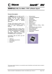
CC2420 – RF Transceiver ................................................................................ 20
3.3
CC2420DBK – Demonstration Board Kit ........................................................ 23
vi
3.3.1
3.4
Atmel ATmega128L Overview ................................................................ 24
TS-7200 overview............................................................................................. 25
CHAPTER4:
SOFTWARE DESCRIPTION .............................................................. 27
4.1
System Setup..................................................................................................... 27
4.2
Atmel Development Environment .................................................................... 28
4.2.1
AVR Studio............................................................................................... 28
4.2.2
WinAVR ................................................................................................... 29
4.3
Linux Environment ........................................................................................... 29
4.3.1
4.4
Cygwin...................................................................................................... 30
Stack Overview................................................................................................. 31
4.4.1
Linux - Media Access control (MAC) ...................................................... 32
4.4.2
Linux – Serial Line Internet Protocol (SLIP) ........................................... 33
4.4.3
Linux – Serial port .................................................................................... 34
4.4.4
ATmega128L – MAC ............................................................................... 34
4.4.5
ATmega128L – SLIP................................................................................ 35
4.4.6
ATmega128L – Serial driver .................................................................... 35
4.5
MAC Communication....................................................................................... 36
4.6
Setup for testing ................................................................................................ 38
CHAPTER5:
5.1
CONCLUSION..................................................................................... 41
Future work....................................................................................................... 42
REFERENCES..................................................................................................................43
APPENDIX: CODE...........................................................................................................46
vii
LIST OF FIGURES
FIGURE 2.1: Star and peer-to-peer networks [4]............................................................... 8
FIGURE 2.2: LR-WPAN device architecture [1]............................................................. 10
FIGURE 2.3: The channel structure in IEEE 802.15.4 [4]............................................... 11
FIGURE 2.4: The PHY packet structure [4]..................................................................... 12
FIGURE 2.5: The format of a genral MAC frame [4]...................................................... 13
FIGURE 2.6: A MAC superframe structure [4] ............................................................... 15
FIGURE 2.7: Communication to a coordinator in a beacon enabled network [1] ........... 16
FIGURE 2.8: Communication to a coordinator in a non beacon enabled network [1] ... 16
FIGURE 2.9: Communication from a coordinator in a beacon enabled network [1]....... 17
FIGURE 2.10: Communication from a coordinator in a nonbeacon enabled network [1]18
FIGURE 3.1: CC2420 simplified block diagram [6]........................................................ 22
FIGURE 3.2: CC2420DB Overview [5]........................................................................... 23
FIGURE 3.3: TS-7200 Hardware Components [8] .......................................................... 26
FIGURE 4.1: Setup overview ........................................................................................... 28
FIGURE 4.2: Software structure and data flow................................................................ 32
FIGURE 4.3: The structure of MAC packet..................................................................... 32
FIGURE 4.4: Packet Transmission Mechanism ............................................................... 36
FIGURE 4.5: Packet receiving mechanism ...................................................................... 37
FIGURE 4.6: Test program menu..................................................................................... 39
FIGURE 4.7: A received frame by test program .............................................................. 39
viii
LIST OF TABLE
TABLE 2.1: Frequency bands and data rates [1].............................................................. 11
ix
LIST OF ABBREVIATIONS
ADC
Analog to Digital Converter
AES
Advanced Encryption Standard
ALU
Arithmetic and Logic Unit
API
Application Program Interface
ARM
Advanced RISC Machine
CC2420DB
CC2420 Development Board
CPU
Central Processing Unit
CRC
Cyclic Redundancy Check
CSMA-CA
Carrier Sense Multiple Access with Collision Avoidance
DHCP
Dynamic Host Configuration Protocol
DLL
Dynamic Link Library
DSSS
Direct Sequence Spread Spectrum
ext2
Extended File System
FCS
Frame Check Sequence
FFD
Full Function device
FIFO
First In First Out
GTS
Guaranteed Time Slots
HAL
Hardware Abstraction Layer
IDE
Integrated Drive Electronics
IDE
Integrated Development Environment
IEEE
Institute of Electrical and Electronics Engineers
IF
Intermediate Frequency
x
IP
Internet Protocol
ISM
Industrial, Scientific, and Medical
ITU-T
Telecommunication Standardization Sector
JTAG
Joint Test Action Group
LAN
Local Area Network
LR-WPAN
Low-Rate Wireless Personal Area Networks
MAC
Medium Access Control Layer
MFR
MAC Footer
MHR
MAC Header
MIPS
Million Instructions Per Second
MMU
Memory Management Unit
MPDU
MAC Protocol Data Unit
NFS
Network File System
OHCI
Open Host Controller Interface
O-QPSK
Offset Quadrature Phase Shift Keying
PA
Power Amplifier
PAN
Personal Area Network
PC
Personal Computer
PDA
Personal Digital Assistant
PHY
Physical Layer
POSIX
Portable Operating System Interface
PPDU
PHY Protocol Data Unit
PSDU
PHY Service Data Unit
xi
PWM
Pulse Width Modulation
RAM
Random Access Memory
RF
Radio Frequency
RFD
Reduced Function Device
RISC
Reduced Instruction Set Computer
RSSI
Received Signal Strength Indication
RTC
Real Time Counter
RXFIFO
Receive First In First Out
SAP
Service Access Points
SBC
Single Board Computer
SDRAM
Synchronous Dynamic RAM
SFD
Start of Frame Delimiter
SLIP
Serial Line IP
SPI
Serial Peripheral Interface
SRAM
Static Random Access Memory
SSH
Secure Shell
TXFIFO
Transmit First In First Out
UART
Universal Asynchronous Receiver/Transmitter
USART
Universal Synchronous Receiver Transmitter
USB
Universal Serial Bus
WPAN
Wireless Personal Area Network
CHAPTER1: INTRODUCTION
There has been tremendous growth in the field of wireless communication during
the last decade. The wide acceptance of 802.11 standards for wireless local area network
(WLAN) and cellular phone networks have proved that low cost wireless solutions are
feasible and acceptable. There are many applications that require low cost, low data rate,
low power and inexpensive solution to network within a small area thus requiring a low
rate wireless personal area network (LR-WPAN). There are many proprietary solutions
that address these needs, but they are expensive and incompatible between
manufacturers. The IEEE 802.15.4 is a new standard for LR-WPAN providing a low cost
and less complicated solution. The expected applications are home/office automation,
industrial sensors and control, distributed sensor networks and environment monitoring
[2].
The silicon implementation of the standard is inexpensive when compared to
other proprietary solutions, as the standard is open and available to everyone. As a result
the chip making companies compete to develop a better product at a lower cost. The cost
of a wireless node is an important factor as some applications require large number of
nodes.
The ZigBee alliance, an association of companies working together to develop
ZigBee standard based products for monitoring and control, has led to the increased
adoption of the IEEE 802.15.4 standard. The ZigBee standard defines upper layer that are
2
built on the IEEE 802.15.4 standard. The aim of the ZigBee alliance is to replace every
switchbox, electrical outlet and various sensors in a building by wireless nodes that
communicate with each other even though manufactured by different manufacturers. This
standard is being widely adopted by the industry and the numbers of products based on
the standard are increasing exponentially. The ZigBee alliance is forecasting that in the
next four to five years time, there could be 50 ZigBee devices per home and eventually as
many as 150 [15].
1.1
Motivation
The IEEE 802.15.4 is a relatively new standard and thus attracts new research on
its various aspects. Many universities are conducting research on the use of different
routing protocols, efficient energy use and coexistence issues of IEEE 802.15.4 with
other wireless technologies. The vast majority of applications will require the use of
embedded devices. The embedded devices used in the IEEE 802.15.4 wireless nodes can
range from a small battery-powered sensor to a large central controller with large
processing power and data storage ability. The central controller can also provide user
interface, connect with other wired/wireless networks and control other devices. These
central controllers require an embedded operating system for their operation as they have
to perform a variety of functions.
Linux is an open-source UNIX like kernel that can be freely distributed under the
terms of GNU General Public License (GPL). Linux was specifically developed as an
operating system for server/desktop environment. Currently there is a lot of interest
among the open source community to customize Linux for embedded applications. Linux
is growing as an embedded operating system of choice because of its advantages such as,
3
no licensing fees, scalability, reliability, a large programmer base and community support
[12]. According to a survey conducted by Venture Development Corporation, a
technology research and marketing firm, Linux owned the highest percentage of new
embedded-development projects of any operating system [13]. Linux is used in industrial
controllers, network routers, commercial devices and home entertainment systems. These
devices are expected to include IEEE 802.15.4 wireless functionality in the near future.
There are many commercial implementations of IEEE 802.15.4 and ZigBee
stack. There are also a few community projects working on implementing an open source
version of the IEEE 802.15.4 stack. The current statuses of these projects indicate that
development has almost come to a stop [25, 26, 27]. The lack of a working open source
implementation of the standard was a big motivation factor to develop one and also
develop the setup as an embedded Linux wireless development platform.
1.2
Current Work
There are currently numerous research projects conducted in various aspects of
IEEE 802.15.4 standard. A paper titled “On the use of IEEE 802.15.4 to enable wireless
sensor networks in building automation” [2] provides an insight into the application of
the standard and its effects on building maintenance, energy consumption, safety and
security. An article “Home networking with ZigBee” [28] presents the comparison of
Bluetooth, ZigBee, 802.11 and other proprietary solutions and shows that ZigBee will
succeed where others failed in home networking.
The results of the work presented in a paper titled “Coexistence of IEEE 802.15.4
with other Systems in the 2.4 GHz –ISM –Band” [3] show that IEEE 802.15.4 can co
exist with other networks , is robust and reliable even in the presence of some
4
interference.
Another paper titled “An Experiment on Performance Study of IEEE
802.15.4 Wireless Networks” [11] presents the results of an experiment conducted to
evaluate the performance of various features such as, direct and indirect transmissions,
CSMA-CA mechanism, data payload size and beacon enabled mode. The data
throughput, delivery ratio and received signal strength were investigated as performance
metrics. The results show that non beacon network has better raw data rates and
utilization ratio as compared to beacon enabled networks.
The hardware board developed by Mr. Assad [29]
is an inexpensive IEEE
802.15.4 evaluation board. Mr. Rai [30] used this setup in evaluating energy consumption
in IEEE 802.15.4 communication. Their work very helpful as it is very important to
determine energy consumption of wireless nodes as they are expected to operate for long
time on small batteries.
A paper titled “Embedded Linux Outlook in PostPC Industry” [14] presents an
analysis of embedded Linux in the industry, how it compares to other commercial
embedded OS. The paper concludes with a forecast in growth of industry adoption of
Linux and proposes standardization measures to sustain the growth. Linux is inherently a
non real-time OS; there have been many efforts to add real-time functionality to Linux
kernel. A paper titled “A Measurement-Based Analysis of the Responsiveness of the
Linux Kernel” [31] presents experiments conducted on various non preemptible sections
of the kernel code and quantified its effects on interrupt latency. The results show the
user-space task do not influence the kernel’s response time to external interrupts. In
general, many of the net applications, network device drivers, several file systems even
5
under heavy fragmentation, do not represent source of unresponsiveness and thus, Linux
can safely adopted in soft real time systems.
With kernel version 2.6.18, basic real-time support is now available in the main
kernel source and thus improves the real time performance. With the growing
advancements in Linux, it is projected to continue its growth as an embedded OS.
1.3
Completed Thesis work
The work started with an investigation of IEEE 802.15.4. It is gaining wide
support from industry for its adoption and attracting new research in various aspects of it.
Further investigation found no open source working implementation of IEEE 802.15.4
for Linux. With Linux gaining foothold in embedded operating systems mainly for it
being open source and the number of devices using Linux is increasing everyday. Many
of these devices will need to add IEEE 802.15.4 functionality to them and the current
work is expected to be helpful in this regard.
Many single board computers were considered and evaluated for their
performance, features, price and software support. A SBC with inadequate support from
the manufacturer in the form of device drivers, kernel patches and operating system will
require enormous individual effort. TS-7200 SBC was selected for its features, good
support by the manufacturer and huge user community. The TS 7200 manufacturer
supports Debian distribution, it is well recognized for its stability and component package
management, it also has a large advanced user community. Debian version 3.0 (‘woody’)
was installed on a 512MB compact flash and TS-7200’s RedBoot boot loader was
6
configured accordingly. Debian hosts development tools for large number of
programming languages this adds to the adaptability of the setup to any system.
The CC2420DBK was selected to be used as IEEE 802.15.4 for its features and
availability of development tools for it in the lab. The possible ways to interface CC2420
to the TS-7200 were (set of designs of system were) evaluated for their flexibility,
modularity and complexity, and the system was designed to have a good balance of these
attributes.
A subset of IEEE 802.15.4 protocol was implemented for Linux in C
programming language. A test program was developed to use the stack and communicate
with another IEEE 802.15.4 device. The setup is developed as an embedded wireless
Linux platform.
The contribution of the work is to provide an open source GPL licensed IEEE
802.15.4 protocol stack and publish a paper on the work. The work also provides a test
setup to evaluate standard on Linux operating system.
1.4
Organization of Thesis
The thesis report is divided into five chapters. Chapter 2 introduces the IEEE
802.15.4 protocol. It discusses various features, network topologies, communication
mechanisms and layer of the protocol. Chapter 3 describes the hardware setup and the
features of the individual components. Chapter 4 introduces the software component. It
describes the software development environment, the Linux environment, the software
stack developed and testing. Chapter 5 details results and conclusions and suggests future
work.
CHAPTER2: INTRODUCTION TO IEEE 802.15.4
The IEEE 802.15 defines the Wireless Personal Area Network (WPAN). The
Task Group 4 is working on defining a standard for low rate WPAN (LR-WPAN). The
standard defines the physical (PHY) and medium access control (MAC) layer
specifications.
The devices that take part in a LR-WPAN can be either a reduced function device
(RFD) or full function device (FFD). The FFD can take one of the three roles, a personal
area network (PAN) coordinator, a coordinator or a device. An FFD can communicate
with other FFDs or RFDs, while an RFD can communicate only with an FFD. An RFD is
intended for simple devices in the network, such as a light switch; which does not operate
continuously or send large data and generally associates with a single FFD. Therefore an
RFD can be implemented with very minimum resources. A WPAN consists of two or
more devices within radio reach communicating on the same physical channel. A WPAN
shall include at least one FFD operating as the PAN coordinator of the network [1].
8
Figure 2.1: Star and peer-to-peer networks [4]
2.1
Network Topologies
A LR-PAN can be setup to operate in either of the two topologies; the star
topology or the peer-to-peer topology. As shown in the Figure 2.1, the PAN coordinator
forms the central node in the star topology. Every device in the network communicates
with the central node. The PAN coordinator is used to initiate, terminate or route
communication around the network. The PAN coordinator is the primary controller of the
network. All devices generally have a 64 bit extended address. This address can be used
or exchanged for a shorter address allocated by the PAN coordinator when the device
associates with the PAN coordinator. The PAN coordinator may be powered by mains
outlet, while the devices generally are battery powered. The applications of star topology
are home automation, personal computer (PC) peripherals, toys and games.
The peer-to-peer topology allows any device to communicate with any other
device within the radio reach, but requires a PAN coordinator to form the network. This
topology allows formation of complex network configurations, such as mesh networking
9
topology. This type of topology is useful in applications such as industrial control and
monitoring, wireless sensor networks monitoring environment, inventory and tracking.
This topology allows the network to be ad hoc, self organizing and self healing. A device
may communicate with other devices out of its radio reach by routing the message
through other devices.
2.2
Architecture
A set of layers is used to describe the architecture of the LR-PAN. Each layer is
responsible for a logical part of the standard and offers services to the higher layers. The
layout of layers is based on the open systems interconnection (OSI) seven-layer model.
An LR-WPAN device comprises of a PHY, which contains the radio frequency
(RF) transceiver along with its low-level control mechanism and a MAC sublayer that
provides access to the physical channel for all types of transfers [1].
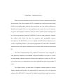
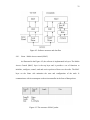
Figure 2.2 illustrates the layer arrangement in the standard. The upper layers
consists of network layer, which is responsible for network configuration and message
routing, and application layer, which provides the intended functionality for the device.
An IEEE 802.2 Type 1 logical link layer (LLC) can access the MAC sublayer through the
service specific convergence sublayer (SSCS) [1]. The LR-WPAN architecture can be
implemented in either an embedded device or as a device requiring support of an external
device such as PC.
10
Figure 2.2: LR-WPAN device architecture [1]
2.3
PHY specification
The PHY layer is expected to provide two services: the PHY data service and
PHY management service interfacing to the physical layer management entity (PLME).
The PHY data service allows the transmission and reception of PHY protocol data units
(PPDU) across the physical radio channel. The features of PHY are activation and
deactivation of the radio transceiver, energy detection (ED), link quality indication,
channel selection, clear channel assessment (CCA), transmission and reception of packets
across the physical medium.
11
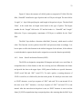
Table 2.1: Frequency bands and data rates [1]
Figure 2.3: The channel structure in IEEE 802.15.4 [4]
The standard offers two PHY options which differ in frequency bands and data
rate. The Error! Reference source not found. summarizes the frequency bands,
modulation and spreading technique.
The standard defines 27 channels, numbered 0 to 26, across the three frequency
bands, as illustrated in Figure 2.3. Sixteen channels are available in the 2450 MHz band,
10 in the 915 MHz band and 1 in 868 MHz band. The relation between the channel
number and centre frequency is defined as:
Fc = 868.3 MHz for k = 0,
(k is the channel number)
12
Fc = 906 + 2(k-1) MHz for k = 1, 2, ..., 10
Fc = 2405 + 5(k-11) MHz for k = 11, 12, …, 26
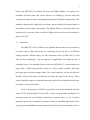
Figure 2.4: The PHY packet structure [4]
Figure 2.4 illustrates a PPDU. Each PPDU contains a synchronization header
(SHR), which consists of a preamble and start of packet delimiter (SFD), a PHY header
(PHR) containing frame length information, and PHY payload or PHY service data unit
(PSDU). The preamble field is used by the transceiver to obtain chip and symbol
synchronization with an incoming message. The preamble field is composed of 32 binary
zeros. The SFD is an 8 bit field indicating the end of preamble and start of packet data.
The PHY header specifies the length of PSDU in bytes. The PSDU field is variable and
carries the actual PHY packet. For all packet types of length five bytes or greater than
seven bytes, the PSDU contains the MAC sublayer frame [4].
2.4
MAC sublayer specification
The MAC sublayer provides two services: the MAC data service and the MAC
management service interfacing to the MAC sublayer management entity (MLME)
13
service access point (SAP).
The MAC data service enables the transmission and
reception of MAC protocol data units (MPDU) across the PHY data service [1].
The features of the MAC sublayer are beacon management, channel access,
guaranteed
time slot
(GTS) management,
frame validation,
association
and
disassociation.
2.4.1
MAC frame format
The MAC frame structure is designed to keep the complexity at a minimum while
ensuring they are sufficiently robust to be transmitted on a noisy channel. The general
format of a MAC frame is shown in the Figure 2.5.
Figure 2.5: The format of a general MAC frame [4]
A MAC frame is composed of the MAC header (MHR), MAC service data unit
(MSDU), and MAC footer (MFR). The first field of the header is the frame control field.
It indicates the type of the MAC frame, specifies format of the address field, and controls
14
acknowledgement. The address field is variable of length 0 to 20 bytes. Based on the
frame type, the address field may contain source and destination addresses, no address or
destination address. A short 8 bit device address or 64 bit IEEE device address may be
used [4].
The payload is of variable length with a restriction of 127 bytes for the complete
MAC frame. The data contained in payload is dependent on the frame type. The 802.15.4
MAC has four different frame types. These are the beacon frame, data frame,
acknowledgement frame and MAC command frames which are used for MAC peer-topeer communication.
The sequence number field is used to identify successful transmission of a frame
when the received acknowledgment frame contains the same sequence number. The
frame check sequence (FCS) is a 16 bit International Telecommunication Union –
Telecommunication Standardization Sector (ITU-T) cyclic redundancy check (CRC) to
ensure data integrity [1].
2.4.2
Superframe structure
The standard allows the optional use of a superframe structure illustrated in
Figure 2.6. The superframe is sent by the coordinator bounded by network beacons. It is
divided into 16 equally sized slots. A device can transmit at any time during the slot, but
must finish before the next superframe beacon. The channel access during the time slots
is contention based. For low latency applications or applications requiring specific data
bandwidth, the PAN coordinator may dedicate portions of the active superframe to that
application. These portions are called guaranteed time slots (GTS). The GTS form the
15
contention free period (CFP), which always appear at the end of the contention access
period (CAP). All contention based transactions must be complete before the CFP begins.
Figure 2.6: A MAC superframe structure [4]
2.4.3
Data transfer model
There are three types of data transfer transactions. The first one is the data transfer
to a coordinator in which a device transmits the data. The second transaction is the data
transfer from a coordinator to the device. The third transaction is the data transfer
between the peer devices.
2.4.3.1 Data transfer to a coordinator
When a device needs to transfer data to a coordinator in a beacon enabled
network, it listens for the beacon, when the device finds a beacon it synchronizes to the
superframe structure. At an appropriate time it transmits data using slotted CSMA-CA to
the coordinator. The coordinator may send an optional acknowledgement frame to
complete the transaction. This sequence is summarized in Figure 2.7.
16
Figure 2.7: Communication to a coordinator in a beacon enabled network [1]
If the device is in a non-beacon enabled network, it transmits the data frame using
an unslotted CSMA-CA, to the coordinator. The coordinator may acknowledge
successful reception with an optional acknowledgment frame. The sequence is
summarized in Figure 2.8.
Figure 2.8: Communication to a coordinator in a non beacon enabled network [1]
2.4.3.2 Data transfer from coordinator
When the coordinator needs to transfer data to a device in a beacon enabled
network, it indicates in the network beacon that data message is pending. The device
periodically listens to the network beacon and if a message is pending, transmits a MAC
17
command requesting the data using slotted CSMA-CA. The coordinator acknowledges
the successful reception of the data request from the device by transmitting an optional
acknowledgement frame. The requested data frame is then sent by the coordinator using
slotted CSMA-CA. The device may send an optional acknowledgement frame. The
coordinator will then remove the frame from its list of pending frames in the beacon. The
sequence is summarized in Figure 2.9 [1].
Figure 2.9: Communication from a coordinator in a beacon enabled network [1]
When the coordinator needs to transfer data to a device in a non beacon enabled
network, it stores the data and waits for the device to make contact and request the data.
The device will send a MAC command requesting the data using unslotted CSMA-CA.
The coordinator may send an optional acknowledgement frame indicating successful
reception of the request. If any data is pending, the coordinator transmits the data using
unslotted CSMA-CA to the device, else it will send a zero length payload frame
18
indicating there is no data available. The device acknowledges successful receptions with
optional acknowledgement frame. The sequence is summarized in Figure 2.10.
Figure 2.10: Communication from a coordinator in a non beacon enabled network [1]
2.4.3.3 Peer-to-peer data transfers
In a peer-to-peer network, every device may communicate with every other
device within its radio reach. In order to achieve this effectively, the devices will need to
either turn their receiver on continuously or synchronize with each other. In the former
case, the devices can communicate using unslotted CSMA-CA. In the latter case, other
synchronization measures have to be used. Description of such measures is left to the
upper layers to decide and is beyond the scope of this standard.
2.4.4
CSMA-CA mechanism
The standard defines two types of channel access methods depending on the
network configuration. Non beacon enabled networks use unslotted CSMA-CA method.
The device wishing to transmit data will wait for a random period of time. If the channel
is found idle, it shall transmit the data, else if the channel was found to be busy, the
19
device waits for another random period of time before trying to access the channel again.
Acknowledgment frames are sent without using CSMA-CA mechanism.
The beacon enabled networks use slotted CSMA-CA mechanism where the
backoff slots are aligned with the start of the beacon transmission. A device wishing to
transmit data during CAP, will locate the boundary of the next backoff slot and then wait
for a random number of backoff slots. If the channel is busy, following this wait, the
device waits for another random number of backoff slots before trying to access the
channel again. If the channel is found idle, the device can begin transmitting on the next
available slot. Acknowledgement and beacon frames are sent without using a CSMA-CA
mechanism [1].
2.4.5
Security
The MAC sublayer provides a baseline security measures such as maintaining an
access control list (ACL) and symmetric cryptography to protect transmitted frames. The
higher layers determine when security is to be used at the MAC sublayer and provide all
the necessary keying material to provide the security services.
This chapter provided a brief introduction to the IEEE 802.15.4 standard. For a
complete specification, readers are advised to refer to the reference [1].
CHAPTER3: HARDWARE DESCRIPTION
3.1
System Architecture
The aim was to use the existing hardware in the lab, keeping the cost down yet
maintaining modularity and expandability in the system. The CC2420 DBK is a
demonstration kit from Chipcon consisting of a pair of CC2420DB boards, each
containing a CC2420 IEEE 802.15.4 compliant RF transceiver and an Atmel
ATmega128L microcontroller. This kit was considered for our familiarity with AVR
microcontrollers and easy availability of JTAGICE mkII debugger for microcontroller.
There are dozens of small single board computers available which are capable of
executing Linux on them varying is physical size, CPU speed and features. Our
requirements were low cost, easily expandable, good support from the manufacturer and
community. A number of SBC’s were considered and TS-7200 from Technologic
systems was selected.
3.2
CC2420 – RF Transceiver
Chipcon was one of the first companies to develop a silicon implementation of the
standard in the form of CC2420 IC. The CC2420 is a true single-chip 2.4GHz IEEE
802.15.4 complaint RF transceiver designed for low power and low voltage applications.
CC2420 includes a digital direct sequence spread spectrum base band modem providing a
spreading gain of 9dB and an effective data rate of 250 kbps.
21
The CC2420 provides extensive hardware support for packet handling, data
buffering, burst transmissions, data encryption, data authentication, clear channel
assessment, link quality indication and packet timing information. These features reduce
the load on the host controller and allow CC2420 to interface with low-cost
microcontrollers. The CC2420 is designed as an SPI slave peripheral.
Figure 3.1 illustrates a simplified block diagram of CC2420, which features a
low- intermediate frequency (IF) receiver. The received RF signal is amplified by the
low-noise amplifier (LNA) and down converted in quadrature (I and Q) to the IF. At IF
(2 MHz), the complex I/Q signal is filtered and amplified, and then digitized by the
ADCs. Automatic gain control, final channel filtering, de-spreading, symbol correlation
and byte synchronization are performed digitally. The SFD pin goes high when a start of
frame delimiter has been detected. CC2420 buffers the incoming data in a 128 byte
receive FIFO buffer. The user may read the FIFO through the SPI interface. CRC is
verified in hardware while the RSSI and correlation values are appended to the frame.
CCA is available on a pin in receive mode [6].
22
.
Figure 3.1: CC2420 simplified block diagram [6]
The CC2420 transmitter is based on direct up-conversion. The data is buffered in
a 128 byte transmit FIFO (separate from the receive FIFO). The preamble and start-offrame delimiter are generated by hardware. Each symbol (4 bits) is spread using the IEEE
802.15.4 spreading sequence to 32 chips and output to the digital-to-analog converters
(DACs). An analog low-pass filter passes the signal to the quadrature (I and Q) upconversion mixers. The RF signal is amplified in the power amplifier (PA) and fed to the
antenna.
23
3.3
CC2420DBK – Demonstration Board Kit
The CC2420DBK Demonstration Board Kit includes two CC2420DB
Demonstration Boards. These boards contain a CC2420 with necessary support
components, an Atmel ATmega128L AVR microcontroller, 32 Kbytes external RAM, a
PCB antenna, as well as a joystick, buttons and LED’s that can be used to implement a
visual user application interface.
The demonstration board is also furnished with
connectors for JTAG, ISP and direct access to CC2420 for expansion [5].
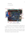
Figure 3.2: CC2420DB Overview [5]
24
Figure 3.2 illustrates the various features on the CC2420DB demonstration board.
The board serves as a development platform. There is an onboard voltage regulator,
which allows it to be powered by either a 9V battery for portability or a wall adaptor of 410V. It has a standard DB9 connector for RS232 communication with the microcontroller
and headers for ISP and JTAG connections, which can be used to program the
microcontroller and debug the application. The ATmega128L has the ability to interface
an external RAM; the board contains a 32KB external RAM, which is quite sufficient for
the program. The board also features a 5-way joystick, buttons and LED’s. A small
potentiometer is connected to the on-chip ADC of ATmega128L.
3.3.1
Atmel ATmega128L Overview
The ATmega128L is a low power CMOS 8-bit microcontroller based on the AVR
enhanced RISC architecture. By executing powerful instructions in a clock cycle, the
ATmega128L achieves throughputs approaching 1 MIPS per MHz. The AVR core
combines a rich instruction set with 32 general-purpose working registers. All the 32
registers are directly connected to the Arithmetic Logic Unit (ALU), allowing two
independent registers to be accessed in one single instruction executed in one clock cycle
[7].
The ATmega128L provides the following features:
•
128K bytes of in-system programmable Flash
•
4K bytes EEPROM
•
4K bytes SRAM
•
Real Time Counter (RTC)
•
2 USART
25
3.4
•
SPI port
•
8-channel, 10-bit ADC
•
Two 8-bit Timer/Counters and two 16-bit Timer/Counters
•
JTAG test interface
TS-7200 overview
The TS-7200 is a compact, full-featured single board computer (SBC. This board
was selected based on its features and the manufacturer provided good support for Linux
by providing precompiled Linux Kernel, Debian distribution and tool-chain. This board is
small in size and priced economically.
TS-7200 is based on the Cirrus EP9302 ARM9 CPU. The EP9302 features an
advanced 200 MHz processor design with a memory management unit (MMU) that
allows support for high level operating systems such as Linux, Windows CE, and others
[8]. As a general-purpose controller, it provides a standard set of peripherals on board.
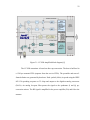
Figure 3.3 illustrates the hardware components on TS-7200 [8].
The features of TS-7200 are:
•
200 MHz ARM9 CPU with MMU
•
8 MB Strata Flash drive (16 MB Optional)
•
32 MB SDRAM (64 MB Optional)
•
True Integrated Drive Electronics (IDE) Compact Flash socket
•
2 USB 2.0 OHCI ports (12 Mbit/s max)
•
2 serial ports ( up to 230 Kbaud)
•
10/100 Ethernet port
•
Watchdog Timer
26
•
SPI bus interface
•
PC/104 expansion bus
Figure 3.3: TS-7200 Hardware Components [8]
The TS-7200 features a true IDE compact Flash socket. A compact Flash card in
the socket appears as a hard drive to the operating system. Compact Flash cards are
available in a wide range of capacities. A 512 MB card is sufficient to install a
customized version of Debian Linux distribution. The board also features USB and
Ethernet ports which can be used to connect to other devices. This board serves right for
a PAN coordinator as it is expected to be the master controller.
CHAPTER4: SOFTWARE DESCRIPTION
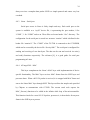
4.1
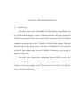
System Setup
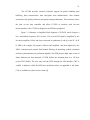
The setup consists of the CC2420DBK, TS-7200, Desktop, Laptop, Router, and
two JTAGICE mkII debuggers. Figure 4.1 illustrates the setup. The laptop, desktop and
TS-7200 were connected to the router to form a local area network (LAN). The desktop
computer is connected to one of the CC2420DB via JTAGICE mkII debugger. This setup
forms one node of the wireless network. The other CC2420DB and TS-7200 connected
via RS-232 form another node and this CC2420DB is connected to the Laptop via
another JTAGICE mkII.
The router is the dynamic host configuration protocol (DHCP) server of the
network. The DHCP server was configured to assign specific Internet Protocol (IP)
addresses to the desktop, laptop and TS-7200 which were 192.168.100, 192.168.0.101
and 192.168.0.102 respectively.
28
Figure 4.1: Setup overview
4.2
4.2.1
Atmel Development Environment
AVR Studio
AVR Studio is an Integrated Development Environment (IDE) for assembling and
debugging AVR application in windows environment. It provides a project management
tool, source file editor and chip simulator and interfaces with the JTAGICE mkII for
downloading and debugging of applications. The AVR Studio also has a symbolic source
level debugger, with features for Break Points, variables watch/ edit, single stepping.
Additional features can be added through the use of plugins.
29
4.2.2
WinAVR
WinAVR is a suite of executable, open source software development tools for the
Atmel AVR series of microcontrollers hosted in windows platform. The installation and
usage instructions can be found in the user manual [24].
The software development tools include:
•
Compilers
•
Assemblers
•
Linker
•
Librarian
•
File converters
•
C Library
•
Debugger
•
In-Circuit Emulator software
•
Many support utilities.
All the software for the ATmega128L microcontroller was developed using
WinAVR tools version 20060421 and AVR Studio version 4.12b.
4.3
Linux Environment
The TS-7200 comes with TS-Linux embedded distribution installed in the on-
board Flash memory. TS-Linux is a compact distribution, based on Busybox, ideal for
small footprint. BusyBox combines tiny versions of many common Linux/UNIX utilities
into a single small executable. A full featured Linux distribution can also be run on either
the Network File System (NFS) root file system or installed on a large CompactFlash
card.
30
The on-board Flash contains the TS-Linux kernel which is a standard kernel with
patches to customize for this hardware. The version of the on-board kernel was ts-8. A
newer version ts-10 based on standard kernel version 2.4.26 was available and the onboard Flash was updated with this version.
A 512MB CompactFlash card was formatted with the second extended file system
(ext2) on a desktop running Linux via a USB – CompactFlash card reader. The
customized Debian 3.0 (Woody) distribution available on Technologic system website
was installed on the CompactFlash card. The configuration of the RedBoot bootloader
was updated to specify the CompactFlash card file system as the root file system to the
kernel.
There are many advantages of running a full featured Linux distribution where the
associated tools, utilities, application and software development environment are
available. The Debian distribution; as a default runs a secure shell (SSH) server. Any
SSH client could be used to login into this Linux. PuTTY is one such client and is
available as free software for many operating environment including windows. Its easy to
install and configure [23]. A terminal over SSH was preferred over the standard terminal
available on the serial port, as this terminal was found to be more stable and the
applications were found to interact well with it.
4.3.1
Cygwin
Cygwin is a Linux-like environment for Windows. It consists of a Dynamic Link
Library (DLL) named cygwin1.dll, which acts as an emulation layer providing substantial
Portable Operating System Interface (POSIX) system call functionality, and a collection
31
of tools, which provide a Linux look and feel. Many of the Linux applications are ported
to execute in Cygwin environment [22].
An NFS server was installed in the Cygwin, the installation steps [17] by H.
Sparks were found helpful. It was setup to run and export a local folder “/usr/Sandy”. The
TS-7200 was configured to mount this folder at location “/mnt/laptop/” automatically on
boot up by adding an entry in the “/etc/fstab” file. This setup would make the folder
visible to both the systems, thus enabling file and application sharing. Additional
installation and configuration information can be found in the Linux NFS how to [16].
Technologic Systems provides Linux programming tools (toolchain) for Cygwin
environment. The toochain was installed on Cygwin, thus allowing Linux applications for
TS-7200 to be built from the Cygwin environment. The Cygwin environment was
preferred over natively building applications on TS-7200, since the laptop computer
offered more computational resources.
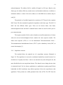
4.4
Stack Overview
The software stack implementation is split into two parts, one part of the stack is
implemented on the Linux side and the other part resides on the ATmega128L
microcontroller. The Linux section implements the device independent higher level
functionality of the stack. The device specific part is implemented on the ATmega128L.
This allows for easy porting to new 802.15.4 RF transceivers.
32
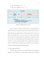
Figure 4.2: Software structure and data flow
4.4.1
Linux - Media Access control (MAC)
As illustrated in the Figure 4.2, the software is implemented in layers. The Media
Access Control (MAC) layer is the top layer and it provides a set of functions to
initialize, configure, control, send and receive packets of data over the radio. The MAC
layer on the Linux side maintains the state and configuration of the node. It
communicates with its counterpart on the microcontroller in the form of data packets.
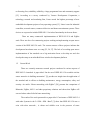
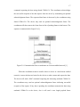
Figure 4.3: The structure of MAC packet
33
Figure 4.3 shows the structure of a MAC packet as composed of 3 fields. The first
field, “FrameID” identifies the type of packet and is of 2 bytes in length. The next field is
“Length”, a 1 byte field specifying the total length of the packet in bytes. The third field
“Data”, is the actual data, its length varies based on the type of packet. The largest
number for the “Length” field can be 255 and the header i.e. “FrameID” and “Length”
fields take 3 bytes, consequently a maximum of 252 bytes is available for the “Data”
field.
The MAC layer defines a function called MAC_Process(), which must be called
often. This function receives packets from SLIP and processes them accordingly. It is
best to place a call to this function in the infinite loop part of the software, if the software
is multi-threaded a separate thread can be assigned to execute this function periodically.
4.4.2
Linux – Serial Line Internet Protocol (SLIP)
The SLIP was designed to encapsulate IP datagram and send it over serial lines. It
encapsulates data to form frames so that the receiving end can differentiate the frames
and provide the data to the upper layers. SLIP protocol defines two special characters:
“END” (octal 300) and “ESC” (octal 333). To send a packet, a starting character of
“END “is sent first, it is followed by the data in the packet. If a data byte is the same code
as “END” character, a two byte sequence of “ESC” and octal 334 is sent instead. If it is
the same as an “ESC” character, a two byte sequence of “ESC” and octal 335 is sent
instead. After the entire data in the packet is sent, an “END” character is sent to end the
frame [9]. SLIP encapsulation drops corrupted packets, thus ensuring that the MAC layer
34
always receives a complete data packet. SLIP is a simple protocol and causes very less
overhead.
4.4.3
Linux – Serial port
Serial port access in Linux is fairly simple and easy. Each serial port on the
system is available as a “ttyS#” device file, # representing the port number, 0 for
“COM1”, 1 for “COM2” and so on. These files are located under “/dev” directory. The
configuration for the serial port is stored in a structure “termios” which is defined in the
header file “termios.h”. The “COM2” of the TS-7200 is connected to the CC2420DB,
which can be accessed by the device file “/dev/ttyAM1”. The serial port is configured for
sending and receiving of raw data bytes. The data can be sent and received via write()
and read() functions respectively. The reference [9], is a good guide for serial port
programming in Linux.
4.4.4
ATmega128L – MAC
This layer complements the Linux’s MAC layer with implementation of device
specific functionality. The MAC layer receives MAC frames from the SLIP layer and
processes them. When a 802.15.4 packet is received, it is wrapped with MAC frame and
sent to the Linux MAC layer through SLIP. This layer utilizes the sample code provided
by Chipcon to communicate with CC2420. The current stack code expects the
MAC_Process() function to be called in the infinite while loop of the microcontroller.
This function checks for a new 802.15.4 packet, processes it, it then checks for any new
frame in the SLIP layer to process.
35
The sample code consists of Hardware definition files, Hardware Abstraction
Layer (HAL) and Basic RF Library. The Hardware definition files define macros to the
registers in the microcontroller and CC2420, thus providing an easier way to access the
hardware. To support program development, hardware abstraction layer presents with
functions and macros to access most of the CC2420 and microcontroller resources. These
functions and macros can be used without hardware specific knowledge. The Basic RF
library provides simple function to send and receive 802.15.4 packets through CC2420.
4.4.5
ATmega128L – SLIP
The SLIP layer functionality is the same as in Linux’s SLIP layer. It encapsulates
every MAC frame being sent and unpacks every received frame and provides it to the
MAC layer. The current implementation buffers a single MAC frame received.
4.4.6
ATmega128L – Serial driver
The serial driver provides an interrupt based buffered mechanism for transmitting
and receiving data. It implements two circular buffers for transmission and reception. The
data being transmitted is copied to the transmit buffer and the transmit interrupt is
triggered. The transmit interrupt routine checks for an available data byte and copies it to
the transmit data register, if the transmit data buffer is empty, it disables further interrupt
triggers. When a byte of data is received in the microcontroller, it triggers the receive
interrupt routine which copies the data byte to receive buffer.
36
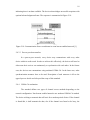
4.5
MAC Communication
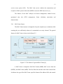
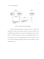
Figure 4.4: Packet Transmission Mechanism
Figure 4.4 illustrates the mechanism to send data from “Node 1” to “Node 2”. The
data packed into a MAC frame and wrapped with SLIP is sent from the TS7200 to the
CC2420DB. The microcontroller receives the frame and identifying as data to transmit,
sends it to CC2420 for transmission over radio. If the acknowledgement option was set,
the microcontroller waits for an acknowledgement from the other node before it times
out, If it receives an valid acknowledgement it forwards it to the Linux MAC else it sends
an transmission error.
37
Figure 4.5: Packet receiving mechanism
Figure 4.5 illustrates the packet reception. The “Node 2” sends a data packet
addressed to “Node 1”. Upon receiving it, the CC2420 interrupts the microcontroller. The
microcontroller gets the data from CC2420 buffer, if the packet requested
acknowledgement, it sends an acknowledgement to CC2420 for transmission. The
microcontroller then encapsulates the data with a MAC frame and sends it to the Linux
SBC.
38
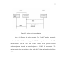
Figure 4.6: The test setup.
4.6
Setup for testing
The system was setup as described in the section 4.1 and illustrated in Figure 4.1.
The sample demo program provided by Chipcon for CC2420DB was used in testing. The
program establishes a point-to-point RF link between two CC2420DB nodes for
communication using the 802.15.4 MAC frames. The program uses 0x2420 as the PAN
ID of the nodes and uses channel 26. The short address of the node is selected based on
the joystick position, if it was pressed down a short address of 0x1234 is selected else if
moved in any direction an address of 0x5678 is selected for the node at startup. If the
potentiometer is turned or the joystick centre button is held down, a data packet
containing the potentiometer value is sent to the other node, which is used to control the
Pulse Width Modulation (PWM) duty cycle thus effectively controlling the brightness of
the Orange LED.
The standalone “Node 2” was programmed with the sample demo program. For
the “Node 1”, a test program was written which would execute on the Linux SBC and use
the stack to communicate with the “Node2”. The test program would perform the same
39
functionality as the demo program, but uses user inputs for the PWM duty cycle and
displays the contents on the received packets.
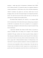
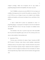
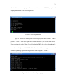
Figure 4.7: Test program menu
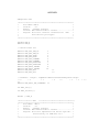
Figure 4.7 shows the menu system of the test program. Menu option 1 sends a
packet to “Node 2” with a user input value for the PWM duty cycle and the node address.
Upon receiving the packet “Node 2” would update the PWM duty cycle value and can be
noticed on the brightness of the LED. Other functions of the test program were tested
similarly by making appropriate changes on the demo program of “Node 2”.
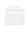
Figure 4.8: A received frame by test program
40
Figure 4.8 shows the contents of a received packet on “Node1” from “Node 2”.
The test program displays the various fields associated with the packet received, it also
displays the raw bytes of the packet.
CHAPTER5: CONCLUSION
The objectives of the thesis work has been achieved with the implementation of
subset features of IEEE 802.15.4 features on a Linux SBC and demonstrate the use of
such a controller in LR-PAN. The SBC with Linux setup and the development tools form
the embedded Linux development system. The complete system with the hardware setup
and the software stack can be used in the following ways.
•
Serves as an embedded Linux development system with the development tools,
other interfaces such as Ethernet and USB, and many applications.
•
Can be used in investigating and developing upper layer protocols such as
ZigBee.
•
Evaluating various aspects of IEEE 802.15.4 protocol.
•
As a tool in the study of co-existence of IEEE 802.15.4 with other wireless
standards.
•
As a packet logger/analyzer in IEEE 802.15.4 networks.
•
As an educational tool in teaching LR-PAN and embedded Linux.
•
As a valuable resource in the ongoing research of IEEE 802.15.4 at UNC
Charlotte.
42
5.1
Future work
This thesis work can be extended in many ways. The stack can be enhanced with
the support for beacon enabled networks. The current version lacks support for security
features, which can be implemented.
The stack can be ported to operating systems such as Windows CE, which is
another popular embedded operating system. As Windows CE is widely used in personal
digital assistants and cell phones, IEEE 802.15.4 wireless functionality can be added to
such devices.
REFERENCES
[1]
Institute of Electrical and Electronic Engineers, Inc., ”IEEE Std. 802.15.42003, IEEE Standard for Information Technology – Telecommunications and
Information Exchange between Systems – Local and Metropolitan Area
Networks – specific Requirements – Part 15.4 : Wireless Medium Access
Control (MAC) and Physical Layer (PHY) Specifications for Low Rate
Wireless Personal Area Networks (LR-WPAN)”
http://standards.ieee.org/getieee802/download/802.15.4-2003.pdf
[2]
J.A. Gutierrez, “On the use of IEEE 802.15.4 to enable wireless sensor
networks in building automation” Proc.of IEEE Int. Conf. Personal, Indoor
and Mobile Radio Communications (PIMRC’04), Barcelona, Spain
September 2004, Vol 3 pp. 1865-1869.
[3]
A. Sikora, V.F. Groza, “Coexistence of IEEE 802.15.4 with other Systems in
the 2.4 GHz- ISM-Band” Proc. of IEEE – Instrumentation and Measurement
Technology Conference (IMTC’05), Ottawa, Canada May 2005, pp 17861791.
[4]
E. Callaway, P. Gorday, L. Hester, J.A.Gutierrez, M. Naeve, B. Heile, V.Bahl
“Home Networking with IEEE 802.15.4: A Developing Standard for LowRate Wireless Personal Area Networks”, IEEE Communication Magazine,
August 2002.
[5]
Chipcon, “User Manual Rev1.3 SmartRF ® CC2420DBK Demonstration
Board Kit”
http://www.chipcon.com/files/CC2420DBK_User_Manual_1_3.pdf
[6]
Chipcon, “SmartRF® CC2420: 2.4GHz IEEE802.15.4/Zigbee RF
Transceiver,” http://www.chipcon.com/files/CC2420_Data_Sheet_1_4.pdf
[7]
ATMEL, ATMEGA 128L AVR 8-Bit RISC – Datasheet
http://www.atmel.com/dyn/resources/prod_documents/doc2467.pdf
[8]
TS-7200
Datasheet.
datasheet.pdf
[9]
G. Frerking, “Serial programming HOW TO”.
http://tldp.org/HOWTO/Serial-Programming-HOWTO/
[10]
J. Romkey “RFC 1055 - Nonstandard for transmission of IP datagrams over
serial lines: SLIP” http://www.faqs.org/rfcs/rfc1055.html
http://www.embeddedarm.com/Manuals/ts-7200-
44
[11]
J. Lee, “ An Experiment on Performance Study of IEEE 802.15.4 Wireless
Networks” Proc. of Emerging Technologies and Factory Automation, 2005
Volume 2, 19-22 Sept. 2005 Page(s):451-458
[12]
A. Lennon, “Embedding Linux” IEE Review Volume 47, Issue 3, May 2001
Page(s):33 – 37
[13]
D. Geer, “Survey: Embedded Linux Ahead of the Pack” Distributed Systems
Online, IEEE Volume 5, Issue 10, Oct. 2004 Page(s):3 – 3
[14]
S. Hong, “Embedded Linux Outlook in the PostPC Industry” Proc. of ObjectOriented Real-Time Distributed Computing, 2003. 14-16 May 2003
Page(s):37 – 40
[15]
C. Evans-Pughe, “Bzzzz zzz [ZigBee wireless standard]” IEE Review
Volume 49, Issue 3, March 2003 Page(s):28 – 31
[16]
C. Smith “Linux NFS-HOWTO” http://nfs.sourceforge.net/nfs-howto/
[17]
H. Sparks “Cygwin NFS Server HOWTO”
http://www.csparks.com/CygwinNFS/index.xhtml
[18]
A. Rodland, “Novice's Guide to AVR Development”
http://www.atmel.com/dyn/resources/prod_documents/novice.pdf
[19]
C. O'Flynn, “Downloading, Installing and Configuring WinAVR”
http://winavr.sourceforge.net/install_config_WinAVR.pdf
[20]
TS-7200 User’s Manual http://www.embeddedarm.com/Manuals/ts-7200manual-rev2.2.pdf
[21]
Linux for ARM on TS-7000 User's Guide
http://www.embeddedarm.com/Manuals/linuxarm-guide-rev2.0.pdf
[22]
Cygwin User/s guide http://cygwin.com/cygwin-ug-net/cygwin-ug-net.html
[23]
PuTTY user manual http://www.putty.nl/0.58/htmldoc/
[24]
WinAVR manual http://winavr.sourceforge.net/install_config_WinAVR.pdf
[25]
Linux wireless sensor LAN project http://linux-802-15-4.sourceforge.net/
[26]
Universal ZigBee Stack http://sourceforge.net/projects/zigzagbee/
45
[27]
ZigBuzz http://sourceforge.net/projects/zigbuzz/
[28]
M. Galeev, “Home Networking with ZigBee”
http://www.embedded.com/showArticle.jhtml?articleID=18902431
[29]
A. H. Ansari “Hardware Development of an Embedded Wireless Evaluation
Board”, MS Thesis, University of North Carolina - Charlotte, Dec. 2005.
[30]
R. Rai "IEEE 802.15.4 Protocol Implementation and Measurement of Current
Consumption", M.S Thesis, University of North Carolina- Charlotte, Dec.
2005.
M. Marchesotti, M. Migliardi, R. Podesta, “A Measurement-Based Analysis
of the Responsiveness of the Linux Kernel” Proc. of International
Symposium and Workshop on Engineering of Computer Based Systems, 2730 March 2006.
[31]
APPENDIX
ATmega128L code
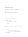
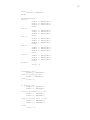
/*********************************************************
*
File Name: MAC.h
*
*
Version:
0.1
*
*
Author:
Sandeep Sirpatil
*
*
License: GNU General Public License................*
*
Purpose: This file contains constansta for MAC
*
*
and function prototypes
*
*
*
*********************************************************/
#ifndef MAC_H
#define MAC_H
// Define Frame IDs
#define
#define
#define
#define
#define
#define
#define
#define
#define
#define
#define
#define
MAC_SET_PAN_ID
MAC_GET_PAN_ID
MAC_SET_ADDR
MAC_GET_ADDR
MAC_SET_CHANNEL
MAC_GET_CHANNEL
MAC_SET_RECEIVER
MAC_GET_RECEIVER
MAC_XMIT_PACKET
MAC_RECV_PACKET
MAC_SET_ACK
MAC_GET_ACK
1
2
3
4
5
6
7
8
9
10
11
12
// FrameID + length + seqNum+SrcAdd+srcPanID+AckReq+Rssi+length
// 2
+ 1
+ 1
+ 2
+ 2
+ 1
+ 1
11
#define MAC_RECV_PKT_OVERHEAD 11
int MAC_Init();
int MAC_Process();
#endif // MAC_H
/************** END
************************************/
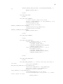
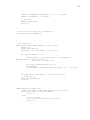
/*********************************************************
*
File Name: MAC.c
*
*
Version:
0.1
*
*
Author:
Sandeep Sirpatil
*
*
License: GNU General Public License................*
*
Purpose: This file implements the device specific *
*
functionality of IEEE 802.15.4
*
*
*
*********************************************************/
+ 1 =
47
#include "include.h"
#include "SLIP.h"
#include "MAC.h"
#define SLIP_TX_BUF_SIZE
#define SLIP_RX_BUF_SIZE
140
140
// Structure for local copy of the received packet
// This RX Struct will get written into when a packet is received from
radio.
// This copy of the received packet should be used for further
processing.
volatile BASIC_RF_RX_INFO rf_rcv_info;
UINT8 rf_rx_buffer[BASIC_RF_MAX_PAYLOAD_SIZE];
volatile UINT8 received_newFrame;
UINT8 slip_TxBuff[SLIP_TX_BUF_SIZE];
UINT8 slip_RxBuff[SLIP_RX_BUF_SIZE];
BASIC_RF_TX_INFO rf_Tx_Info;
UINT8 rf_Tx_Buffer[BASIC_RF_MAX_PAYLOAD_SIZE];
//extern volatile BASIC_RF_TX_INFO rf_Tx_Info;
// Initialize function
int MAC_Init(){
rf_rcv_info.pPayload = rf_rx_buffer;
rf_Tx_Info.pPayload = rf_Tx_Buffer;
received_newFrame = FALSE;
return 0;
}
// Primarily handles packets to be received by SLIP and transmitted via
radio.
// and handle packets received via radio to be sent over SLIP.
int mac_pr_ctr =0;
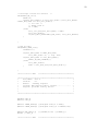
int MAC_Process(){
UINT16 slipRxLength;
int i=0;
if(received_newFrame == TRUE){ // got a new frame from radio
// Make a new SLIP frame and send it
slip_TxBuff[0] = LOWER_BYTE(MAC_RECV_PACKET);
slip_TxBuff[1] = UPPER_BYTE(MAC_RECV_PACKET);
slip_TxBuff[2] = MAC_RECV_PKT_OVERHEAD +
rf_rcv_info.length;
slip_TxBuff[3] = rf_rcv_info.seqNumber;
48
slip_TxBuff[4] = LOWER_BYTE(rf_rcv_info.srcAddr);
slip_TxBuff[5] = UPPER_BYTE(rf_rcv_info.srcAddr);
slip_TxBuff[6] = LOWER_BYTE(rf_rcv_info.srcPanId);
slip_TxBuff[7] = UPPER_BYTE(rf_rcv_info.srcPanId);
slip_TxBuff[8] = rf_rcv_info.ackRequest;
slip_TxBuff[9] = rf_rcv_info.rssi;
slip_TxBuff[10] = rf_rcv_info.length;
memcpy(
&slip_TxBuff[MAC_RECV_PKT_OVERHEAD],rf_rcv_info.pPayload,rf_rcv_info.le
ngth);
//for (i=0; i< rf_rcv_info.length; i++){
//
slip_TxBuff[MAC_RECV_PKT_OVERHEAD+i] =
rf_rcv_info.pPayload[i];
//
}
SLIP_Send(slip_TxBuff,
MAC_RECV_PKT_OVERHEAD+rf_rcv_info.length);
mac_pr_ctr++;
received_newFrame = FALSE; // clear flag
}
// check for new any frames received on SLIP and process them
SLIP_process();
if(
SLIP_getFrame(slip_RxBuff, &slipRxLength) ==0){
// got a SLIP frame process it
unsigned int frameId;
frameId = GET_INT(slip_RxBuff[1], slip_RxBuff[0]);
switch(frameId){
MAC_SET_PAN_ID :{
UINT8 n;
UINT16 panid =
GET_INT(slip_RxBuff[4],slip_RxBuff[3]);
rfSettings.panId = panid;
case
halRfWaitForCrystalOscillator();
DISABLE_GLOBAL_INT();
//FASTSPI_WRITE_RAM_LE(&myAddr,
CC2420RAM_SHORTADDR, 2, n);
FASTSPI_WRITE_RAM_LE(&panid, CC2420RAM_PANID, 2, n);
ENABLE_GLOBAL_INT();
}
break;
case MAC_GET_PAN_ID:
break;
case MAC_SET_ADDR :{
UINT8 n;
UINT16 addr =
GET_INT(slip_RxBuff[4],slip_RxBuff[3]);
rfSettings.myAddr = addr;
halRfWaitForCrystalOscillator();
DISABLE_GLOBAL_INT();
49
FASTSPI_WRITE_RAM_LE(&addr, CC2420RAM_SHORTADDR, 2,
n);
ENABLE_GLOBAL_INT();
}
break;
case MAC_GET_ADDR:
break;
case MAC_SET_CHANNEL:
// check channel range 11-26 valid
if( 10 < slip_RxBuff[3] && slip_RxBuff[3] <27){
DISABLE_GLOBAL_INT();
// if on turn it off
if(rfSettings.receiveOn)
FASTSPI_STROBE(CC2420_SRFOFF);
halRfSetChannel(slip_RxBuff[3]);
if(rfSettings.receiveOn)
FASTSPI_STROBE(CC2420_SRXON);
ENABLE_GLOBAL_INT();
}
break;
case MAC_GET_CHANNEL:
break;
case MAC_SET_RECEIVER:
if(slip_RxBuff[3]==0){ // rx off
basicRfReceiveOff();
//DISABLE_GLOBAL_INT();
//FASTSPI_STROBE(CC2420_SRFOFF);
//ENABLE_GLOBAL_INT();
}else if(slip_RxBuff[3]==1){ // rx on
basicRfReceiveOn();
//DISABLE_GLOBAL_INT();
//FASTSPI_STROBE(CC2420_SRXON);
//ENABLE_GLOBAL_INT();
}
break;
case MAC_GET_RECEIVER:
break;
case MAC_XMIT_PACKET:{ // receive from slip and send it
via radio
rf_Tx_Info.destAddr =
GET_INT(slip_RxBuff[4],slip_RxBuff[3]);
rf_Tx_Info.ackRequest = slip_RxBuff[5];
rf_Tx_Info.length = slip_RxBuff[6];
memcpy(rf_Tx_Info.pPayload,
&slip_RxBuff[7],slip_RxBuff[6]);
//basicRfSendPacket( rf_Tx_Info);
if( basicRfSendPacket( &rf_Tx_Info) ){ //TODO:
return status via SLIP
TOGGLE_YLED();
50
}else{
TOGGLE_RLED();
}
}
break;
case MAC_RECV_PACKET:
break;
}
}
return 0;
}
UINT16 rx_cntr =0;
BASIC_RF_RX_INFO* basicRfReceivePacket(BASIC_RF_RX_INFO *pRRI) {
//
int i=0;
// Adjust the led brightness
//
PWM0_SET_DUTY_CYCLE(pRRI->pPayload[0]);
//
//
//
// Blink the green LED
SET_GLED();
halWait(10000);
CLR_GLED();
rf_rcv_info.seqNumber = pRRI->seqNumber;
rf_rcv_info.srcAddr = pRRI->srcAddr;
rf_rcv_info.srcPanId = pRRI->srcPanId;
rf_rcv_info.length = pRRI->length;
rf_rcv_info.ackRequest = pRRI->ackRequest;
rf_rcv_info.rssi = pRRI->rssi;
memcpy(rf_rcv_info.pPayload, pRRI->pPayload, pRRI->length);
received_newFrame = TRUE;
TOGGLE_GLED();
rx_cntr++;
//
//
//
for(i=0; i<pRRI->length;i++){
rf_rcv_info.pPayload[i]= pRRI->pPayload[i];
}
// Continue using the (one and only) reception structure
return pRRI;
} // basicRfReceivePacket
/************** END
************************************/
51
/*********************************************************
*
File Name: SLIP.h
*
*
Version:
0.1
*
*
Author:
Sandeep Sirpatil
*
*
License: GNU General Public License................*
*
Purpose: This file contains SLIP configuration
*
*
and function prototypes
*
*
*
*********************************************************/
#ifndef SLIP_H
#define SLIP_H
#define
#define
#define
#define
END
ESC
ESC_END
ESC_ESC
0300
0333
0334
0335
/*
/*
/*
/*
indicates end of packet */
indicates byte stuffing */
ESC ESC_END means END data byte */
ESC ESC_ESC means ESC data byte */
int SLIP_Init();
int SLIP_Send(unsigned char *buf, int length);
void SLIP_process();
int SLIP_getFrame(UINT8 *buf, UINT16 *size);
#endif // SLIP_H
/************** END
************************************/
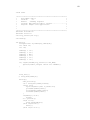
/*********************************************************
*
File Name: SLIP.c
*
*
Version:
0.1
*
*
Author:
Sandeep Sirpatil
*
*
License: GNU General Public License................*
*
Purpose: This file implements SLIP layer and
*
*
uses UART layer as serial driver
*
*
*
*********************************************************/
#include <include.h>
#include "USART.h"
#include "SLIP.h"
#define SLIP_TXBUF_SIZE
#define SLIP_RXBUF_SIZE
200
250
UINT8 slip_xmit_buf[SLIP_TXBUF_SIZE];
UINT8 rx_lastByte;
52
struct Slip_Rcv_Frame{
UINT8 buffer[SLIP_RXBUF_SIZE];
UINT16 length;
UINT8 isEmpty;
UINT8 writeFlag;
};
struct Slip_Rcv_Frame slip_rcv_frame;
int SLIP_Init(){
slip_rcv_frame.isEmpty = TRUE;
slip_rcv_frame.length = 0;
slip_rcv_frame.writeFlag = FALSE;
return 0;
}
int SLIP_Send(unsigned char *buf, int length){
int idx=0;
int i=0;
slip_xmit_buf[idx] = END;
idx++;
for(i=0;i<length;i++){
if(idx+2 >SLIP_TXBUF_SIZE){
return -1; // Buffer overflow
}
switch(buf[i]){
case END:
slip_xmit_buf[idx] = ESC;
idx++;
slip_xmit_buf[idx] = ESC_END;
idx++;
break;
case ESC:
slip_xmit_buf[idx] = ESC;
idx++;
slip_xmit_buf[idx] = ESC_ESC;
idx++;
break;
default:
slip_xmit_buf[idx] = buf[i];
idx++;
}
}
slip_xmit_buf[idx] = END;
idx++;
return( USART1_Send( idx, slip_xmit_buf));
}
int SLIP_getFrame(UINT8 *buf, UINT16 *size){
UINT16 i;
53
// check the frame status
if(slip_rcv_frame.isEmpty == FALSE){ // containe a new frame.
// If new frame is available, copy the data and clear the
receiveframe
for(i=0;i<slip_rcv_frame.length; i++){
buf[i] = slip_rcv_frame.buffer[i];
}
*size = slip_rcv_frame.length;
slip_rcv_frame.isEmpty = TRUE;
return 0;
}else{
// If no new frame avialable retunr -1
return -1;
}
}
/* This function is to be called as many times as possible.
It checks the receiveframe, if found empty, it tries to get data
from the
USART layer and assemble a new frame.*/
void SLIP_process(){
UINT8 ch;
int moredata =1;
if(slip_rcv_frame.isEmpty == TRUE){
if(slip_rcv_frame.writeFlag == FALSE){ // beginning of a new
frame
slip_rcv_frame.length = 0;
}
while(moredata == TRUE){ // a getdata flag
if(USART1_Recv(&ch) ==0){ // if a byte is received then
process it
switch(ch){
case END:
if(slip_rcv_frame.writeFlag ==FALSE){ //start
of new frame
slip_rcv_frame.writeFlag = TRUE; //
indicate the write is in progress
}else{ // End of frame received.
slip_rcv_frame.isEmpty = FALSE; //
indicate a new frame is stored.
slip_rcv_frame.writeFlag =
FALSE;
moredata = FALSE; // end the while loop
}
break;
case ESC:
54
rx_lastByte = ESC; // keep a record of it
break;
case ESC_END:
if(rx_lastByte == ESC){
slip_rcv_frame.buffer[slip_rcv_frame.length] = END;
slip_rcv_frame.length++;
rx_lastByte = 0;
}else{ // TODO: handle error
}
break;
case ESC_ESC:
if(rx_lastByte == ESC){
slip_rcv_frame.buffer[slip_rcv_frame.length] = ESC;
slip_rcv_frame.length++;
rx_lastByte = 0;
}else{ // TODO: handle error
}
break;
default:
slip_rcv_frame.buffer[slip_rcv_frame.length]
= ch;
slip_rcv_frame.length++;
}
}else{ // no more data in Queue
moredata = FALSE;
}
} // while
}
}
/************** END
************************************/
/*********************************************************
*
File Name: USART.h
*
*
Version:
0.1
*
*
Author:
Sandeep Sirpatil
*
*
License: GNU General Public License................*
*
Purpose: Provides varios configuration options for *
*
UART driver.
*
*
*
*********************************************************/
#ifndef USART_H
#define USART_H
//#define USART_2XMODE
1; // Puts USART in 2x mode. not preferred.
#ifdef USART_2XMODE
// (CPUCLOCK / 8*baud) -1
#define UART_BAUD_2K4
416
55
#define
#define
#define
#define
#define
#define
#define
#define
#define
#define
#define
#define
#define
UART_BAUD_4K8
UART_BAUD_9K6
UART_BAUD_14K4
UART_BAUD_19K2
UART_BAUD_28K8
UART_BAUD_38K4
UART_BAUD_57K6
UART_BAUD_76K8
UART_BAUD_115K2
UART_BAUD_230K4
UART_BAUD_250K
UART_BAUD_500K
UART_BAUD_1M
207
103
68
51
34
25
16
12
8
3
3
1
0
#else
// (CPUCLOCK / 16*baud) -1
#define UART_BAUD_2K4
#define UART_BAUD_4K8
#define UART_BAUD_9K6
#define UART_BAUD_14K4
#define UART_BAUD_19K2
#define UART_BAUD_28K8
#define UART_BAUD_38K4
#define UART_BAUD_57K6
#define UART_BAUD_76K8
#define UART_BAUD_115K2
#define UART_BAUD_230K4
#define UART_BAUD_250K
#define UART_BAUD_500K
// #define UART_BAUD_1M
207
103
51
34
25
16
12
8
6
3
1
1
0
0 // not supported
#endif
#define XMIT_BUF_SIZE
#define RECV_BUF_SIZE
extern volatile
extern volatile
UINT8
UINT8
250
250
uart_xmit_buf[XMIT_BUF_SIZE];
uart_xmit_buf[RECV_BUF_SIZE];
UINT8 USART1_Send( UINT8, UINT8* );
UINT8 USART1_Init( UINT8 , UINT8, UINT8, UINT8);
UINT8 USART1_Recv(UINT8* );
#endif
/************** END
************************************/
56
/*********************************************************
*
File Name: USART.c
*
*
Version:
0.1
*
*
Author:
Sandeep Sirpatil
*
*
License: GNU General Public License................*
*
Purpose: A circular buffer device driver for UART *
*
*
*
*
*********************************************************/
#include <include.h>
#include "USART.h"
#define UART1_TX_INT_ENABLE()
(0)
#define UART1_TX_INT_DISABLE()
(0)
volatile
volatile
volatile
volatile
UINT8
UINT8
UINT16
UINT16
volatile
volatile
UINT16 uart_Xmit_Ridx =0;
UINT16 uart_Xmit_Widx =0;
volatile
volatile
volatile
UINT16 txISRCntr =0;
UINT16 rxISRCntr =0;
UINT8 rxChar =0;
do { UCSR1B |= BM(UDRIE1); } while
do { UCSR1B &= ~BM(UDRIE1); } while
uart_xmit_buf[XMIT_BUF_SIZE];
uart_recv_buf[RECV_BUF_SIZE];
uart_Recv_Ridx =0;
uart_Recv_Widx =0;
/* Initialize
UINT8 baud
UINT8 databits = Num of databits, generally 8
UINT8 stopbits = Num of stop bits, generally 1
UINT8 parity = 0-no parity, 1-even, 2- odd
*/
UINT8 USART1_Init( UINT8 baud, UINT8 databits, UINT8 stopbits, UINT8
parity ){
//INIT_UART1(UART_BAUDRATE_9K6,(UART_OPT_8_BITS_PER_CHAR||UART_OPT_ONE_
STOP_BIT||UART_OPT_NO_PARITY));
// disable global int
DISABLE_GLOBAL_INT();
UBRR1H = (unsigned char) baud >>8;
UBRR1L = baud;
UCSR1A &= ~0x01; // Multi procesor disable
UCSR1B = 0; // default state
UCSR1C = 0x06; // default
#ifdef USART_2XMODE
UCSR1A |= BM(U2X1);
57
#else
UCSR1A &= ~BM(U2X1);
#endif
switch(databits){
case 5:
UCSR1C
UCSR1C
UCSR1B
break;
case 6:
UCSR1C
UCSR1C
UCSR1B
break;
case 7:
UCSR1C
UCSR1C
UCSR1B
break;
case 8:
UCSR1C
UCSR1C
UCSR1B
break;
case 9:
UCSR1C
UCSR1C
UCSR1B
break;
default:
return
&= ~BM(UCSZ10);
&= ~BM(UCSZ11);
&= ~BM(UCSZ12);
|= BM(UCSZ10);
&= ~BM(UCSZ11);
&= ~BM(UCSZ12);
&= ~BM(UCSZ10);
|= BM(UCSZ11);
&= ~BM(UCSZ12);
|= BM(UCSZ10);
|= BM(UCSZ11);
&= ~BM(UCSZ12);
|=
|=
|=
BM(UCSZ10);
BM(UCSZ11);
BM(UCSZ12);
-1;
}
if(stopbits ==1){
UCSR1C &= ~BM(USBS1);
}else if (stopbits ==2){
UCSR1C |= BM(USBS1);
}else{
return -1;
}
if (parity ==0){
UCSR1C &= ~BM(UPM11);
UCSR1C &= ~BM(UPM10);
}else if (parity==1){ // even
UCSR1C |= BM(UPM11);
UCSR1C &= ~BM(UPM10);
}else if (parity ==2){ // odd
UCSR1C |= BM(UPM11);
UCSR1C |= BM(UPM10);
}else{
return -1;
58
}
UCSR1B |= (BM(RXEN1)|BM(RXCIE1)); // rx | int enable
UCSR1B |= BM(TXEN1); //tx enable
// Initialize
ENABLE_GLOBAL_INT();
return 0;
}
/* Starts the interrupts for transmission*/
void USART1_startTx(UINT8 ch){
}
/* send function*/
UINT8 USART1_Send( UINT8 numBytes, UINT8* arry){
UINT16 i=0;
UINT16 xmit_Widx =0;
xmit_Widx = uart_Xmit_Widx; // local copy
for (i=0;i<numBytes; i++){
if(xmit_Widx+1 == uart_Xmit_Ridx ||( xmit_Widx+1 ==
XMIT_BUF_SIZE && !uart_Xmit_Ridx)){
return -1; // buffer full
}
uart_xmit_buf[xmit_Widx]= arry[i];
xmit_Widx++;
if(xmit_Widx == XMIT_BUF_SIZE) xmit_Widx = 0; // loop back
}
uart_Xmit_Widx = xmit_Widx; // restore the pointer
// enable TX int
UART1_TX_INT_ENABLE();
return 0;
}
UINT8 USART1_Recv(UINT8 *ch){
if(uart_Recv_Ridx == RECV_BUF_SIZE) uart_Recv_Ridx =0;
if(uart_Recv_Ridx == uart_Recv_Widx){
return -1;
}else{
uart_Recv_Ridx++;
*ch = uart_recv_buf[uart_Recv_Ridx-1];
return 0;
}
}
59
/* Interrupt routine for Receive */
ISR(USART1_RX_vect){
UINT8 ch;
if(uart_Recv_Widx+1 == uart_Recv_Ridx ||(uart_Recv_Widx+1
==RECV_BUF_SIZE && !uart_Recv_Ridx)){
// err cntr ++
// dummy read ??
ch = UDR1;
}else{
uart_recv_buf[uart_Recv_Widx] = UDR1;
uart_Recv_Widx++;
if(uart_Recv_Widx==RECV_BUF_SIZE ) uart_Recv_Widx=0;
}
}
/* ISR for TX*/
ISR(USART1_UDRE_vect){
txISRCntr++;
if(uart_Xmit_Ridx == XMIT_BUF_SIZE)
uart_Xmit_Ridx = 0; // loop back
if(uart_Xmit_Ridx == uart_Xmit_Widx){
UART1_TX_INT_DISABLE();
}else{
uart_Xmit_Ridx++;
UDR1 = uart_xmit_buf[uart_Xmit_Ridx-1];
}
}
/************** END
************************************/
/**********************************************************
*
File Name: util.h
*
*
Version:
0.1
*
*
Author:
Sandeep Sirpatil
*
*
License: GNU General Public License............... .*
*
Purpose: provides utility macros
*
*
*
*
*
**********************************************************/
#ifndef UTIL_H
#define UTIL_H
#define LOWER_BYTE(x) ((unsigned char)(x & 0xFF))
#define UPPER_BYTE(x) ((unsigned char)((x & 0xFF00)>>8))
#define GET_INT(x,y)
#endif // UTIL_H
((((UINT8)x)<<8) |((UINT8)y))
/************** END
************************************/
60
Linux Code:
/*********************************************************
*
File Name: main.c
*
*
Version:
0.1
*
*
Author:
Sandeep Sirpatil
*
*
License: GNU General Public License................*
*
Purpose: Sample test application
*
*
*
*
*
*********************************************************/
#include "include.h"
#include <errno.h>
void sig_catcher(int sig);
void menu();
int main(){
unsigned char ch,rxBuf[50],txBuf[50];
int rxLen =0;
int rtn;
txBuf[0]
txBuf[1]
txBuf[2]
txBuf[3]
txBuf[4]
txBuf[5]
=
=
=
=
=
=
'A';
'B';
ESC;
'D';
'E';
'F';
if( signal(SIGINT,sig_catcher)== SIG_ERR){
fprintf(stderr,"Sigset cannot set SIGINT");
}
SLIP_Init();
// SLIP_Send(txBuf,6);
while(1){
SLIP_Process();
rtn = SLIP_Recv(rxBuf,&rxLen);
if(rtn ==0){
fprintf(stderr,"Got a packet\n");
printBuf(rxBuf,rxLen);
printPacket(rxBuf,rxLen);
clearBuf(rxBuf,rxLen);
}
if(rxBuf[0] =='X')
break;
ch = getchar();
if(ch =='z'){
SLIP_Send(txBuf,6);
}else if(ch=='m'){
menu();
}else if(ch =='a'){
61
int duty;
fprintf(stderr,"inside");
txBuf[0]= LOWER_BYTE(MAC_XMIT_PACKET);
txBuf[1]= UPPER_BYTE(MAC_XMIT_PACKET);
txBuf[2]= 17; // length
txBuf[3]= 0x34;
txBuf[4]= 0x12;
txBuf[5]=TRUE; // ack request
txBuf[6]=10;
//duty = getchar();
//duty = getchar();
//fprintf(stderr," before Errno %d %d",errno,rtn);
scanf("%d",&duty);
//rtn = fscanf(stdin, "Duty cycle %d",&duty);
//fprintf(stderr,"Errno %d %d",errno,rtn);
txBuf[7]=LOWER_BYTE(duty);
// txBuf[7]=0xDE;
SLIP_Send(txBuf,17);
}
fprintf(stderr,".");
sleep(1);
}
SLIP_Term();
return 0;
}
void sig_catcher(int sig){
fprintf(stderr,"SIG caught");
SLIP_Term();
exit(EXIT_FAILURE);
perror("SIGINT: port closed and exit.");
}
void menu(){
unsigned char txBuf[50];
int menu;
fprintf(stderr,"\n## Menu System ##\n");
fprintf(stderr, "1) Send Packet \n");
fprintf(stderr,"2) Set Channel \n");
fprintf(stderr,"3) set Short Address\n");
fprintf(stderr,"4) set Receiver control \n");
fprintf(stderr,"5) set PAN ID \n");
scanf("%d",&menu);
switch(menu){
case 1:{
int add=0,duty;
txBuf[0]= LOWER_BYTE(MAC_XMIT_PACKET);
txBuf[1]= UPPER_BYTE(MAC_XMIT_PACKET);
txBuf[2]= 17; // length
62
txBuf[3]= 0x34;
txBuf[4]= 0x12;
txBuf[5]=TRUE; // ack request
txBuf[6]=10;
fprintf(stderr," Dest Addr in hex");
scanf("%X",&add);
if(add!=0){
txBuf[3] =LOWER_BYTE(add);
txBuf[4] =UPPER_BYTE(add);
}
fprintf(stderr,"LED Duty Cycle ");
scanf("%d",&duty);
txBuf[7]=LOWER_BYTE(duty);
SLIP_Send(txBuf,17);
fprintf(stderr,"\n");
}break;
case 2:{
int chnl =0;
txBuf[0]= LOWER_BYTE(MAC_SET_CHANNEL);
txBuf[1]= UPPER_BYTE(MAC_SET_CHANNEL);
txBuf[2]= 4; // length
fprintf(stderr,"\nChannel range 11-26 :");
scanf("%d",&chnl);
while((chnl < 11 )|| (chnl > 26)){
fprintf(stderr,"\nIncorrect Channel");
scanf("%d",&chnl);
}
txBuf[3] = LOWER_BYTE(chnl);
SLIP_Send(txBuf,4);
}break;
case 3:{
int addr;
txBuf[0]=LOWER_BYTE(MAC_SET_ADDR);
txBuf[1]=UPPER_BYTE(MAC_SET_ADDR);
txBuf[2]=5;
fprintf(stderr,"\nNode address in Hex:");
scanf("%X",&addr);
txBuf[3] = LOWER_BYTE(addr);
txBuf[4] = UPPER_BYTE(addr);
SLIP_Send(txBuf,5);
}break;
case 4:{
int rxCntrl;
txBuf[0]=LOWER_BYTE(MAC_SET_RECEIVER);
txBuf[1]=UPPER_BYTE(MAC_SET_RECEIVER);
txBuf[2]=4;
fprintf(stderr,"\nReceiver control 1-0n, 0-Off");
scanf("%d",&rxCntrl);
while((rxCntrl!=0) &&(rxCntrl!=1)){
fprintf(stderr,"\nIncorrect:");
scanf("%d",&rxCntrl);
}
txBuf[3]=LOWER_BYTE(rxCntrl);
SLIP_Send(txBuf,4);
}break;
case 5:{
63
int panId;
txBuf[0]=LOWER_BYTE(MAC_SET_PAN_ID);
txBuf[1]=UPPER_BYTE(MAC_SET_PAN_ID);
txBuf[2]=5;
fprintf(stderr,"\nSet PanID in HEx ");
scanf("%X",&panId);
txBuf[3]=LOWER_BYTE(panId);
txBuf[4]=UPPER_BYTE(panId);
SLIP_Send(txBuf,5);
}break;
default:
fprintf(stderr,"Incorrect choice");
}
}
/************** END
************************************/
/*********************************************************
*
File Name: MAC.h
*
*
Version:
0.1
*
*
Author:
Sandeep Sirpatil
*
*
License: GNU General Public License................*
*
Purpose: This file contains constants for MAC
*
*
and function prototypes
*
*
*
*********************************************************/
#ifndef MAC_H
#define MAC_H
#define
#define
#define
#define
#define
#define
#define
#define
#define
#define
#define
#define
MAC_SET_PAN_ID
MAC_GET_PAN_ID
MAC_SET_ADDR
MAC_GET_ADDR
MAC_SET_CHANNEL
MAC_GET_CHANNEL
MAC_SET_RECEIVER
MAC_GET_RECEIVER
MAC_XMIT_PACKET
MAC_RECV_PACKET
MAC_SET_ACK
MAC_GET_ACK
1
2
3
4
5
6
7
8
9
10
11
12
// FrameID + length + seqNum+SrcAdd+srcPanID+AckReq+Rssi+length
// 2
+ 1
+ 1
+ 2
+ 2
+ 1
+ 1
11
#define MAC_RECV_PKT_OVERHEAD 11
#endif //MAC_H
/************** END
************************************/
+ 1 =
64
/*********************************************************
*
File Name: SLIP.h
*
*
Version:
0.1
*
*
Author:
Sandeep Sirpatil
*
*
License: GNU General Public License................*
*
Purpose: This file contains SLIP configuration
*
*
and function prototypes
*
*
*
*********************************************************/
#ifndef SLIP_H
#define SLIP_H
/* SLIP
#define
#define
#define
*/
#define
*/
definitions */
END
ESC
ESC_END
0300
0333
0334
/* indicates end of packet 0xC0 */
/* indicates byte stuffing 0xDB */
/* ESC ESC_END means END data byte 0xDC
ESC_ESC
0335
/* ESC ESC_ESC means ESC data byte 0xDD
#define SLIP_TX_BUFF_SIZE 250
#define SLIP_RX_BUFF_SIZE 500
#define FRAME_SIZE 250
/* Serial port definitions */
#define BAUD_RATE B9600
//#define BAUD_RATE
//#define BAUD_RATE
//#define BAUD_RATE
#define PORT
B57600
B115200
B230400
"/dev/ttyAM1"
/* Function declerations*/
int SLIP_Init();
int SLIP_Term();
int SLIP_Process();
int SLIP_Send(unsigned char *buf, int len);
int SLIP_Recv(unsigned char *buf,int *length);
#endif //SLIP_H
/************** END
************************************/
/*********************************************************
*
File Name: SLIP.c
*
*
Version:
0.1
*
*
Author:
Sandeep Sirpatil
*
*
License: GNU General Public License................*
*
Purpose: This file implements SLIP Layer
*
*
*
*
*
*********************************************************/
/* The file contains the code to interface to the serial port
65
and send and receive SLIP frames*/
#include "include.h"
// Receive Circular buffer
static int rx_rdIdx =0;
static int rx_wrIdx = 0;
static unsigned char rx_buffer[SLIP_RX_BUFF_SIZE];
static unsigned char rx_lastByte;
struct rxFrame{
unsigned char buffer[FRAME_SIZE];
int length;
int isEmpty;
int writeFlag;
};
struct rxFrame rx_frame;
struct termios oldconfig, newconfig;
int fd;
/* Function definitions of local functions */
int port_Open();
int port_Close();
int rx_putByte( char c);
int rx_getByte(unsigned char *c);
int SLIP_Init(){
rx_frame.isEmpty = TRUE;
rx_frame.writeFlag = FALSE;
rx_frame.length =0;
fd = 0;
return (port_Open());
}
int SLIP_Term(){
return (port_Close());
}
int port_Open(){
int ret;
/* O_NOCTTY - this is not the controlling terminal program else
Cntr-C will close process */
/* O_NDELAY or O_NONBLOCK - Do not care abt DCD line status and
non blocking read*/
//fd = open("/dev/ttyAM1", O_RDWR | O_NOCTTY | O_NDELAY);
fd = open(PORT, O_RDWR | O_NOCTTY | O_NDELAY);
if(fd == -1){
return -1; // port open failed
}
tcgetattr(fd, &oldconfig); // save the old config
66
tcgetattr(fd, &newconfig);
// Set the port speed parameters
cfsetispeed(&newconfig, BAUD_RATE);
cfsetospeed(&newconfig, BAUD_RATE);
// 8N1
newconfig.c_cflag &= ~PARENB;
newconfig.c_cflag &= ~CSTOPB;
newconfig.c_cflag &= ~CSIZE;
newconfig.c_cflag |= CS8;
newconfig.c_cflag &= ~CRTSCTS; // No Flow control
newconfig.c_cflag |= (CLOCAL | CREAD); // local line no ownew
change and enable receiver
// set line parameters for raw input; ie no processing
newconfig.c_lflag &= ~(ICANON |ECHO|ECHOE| ISIG);
// Input flags
newconfig.c_iflag &= ~(IXON|IXOFF |IXANY);
// Output flags
newconfig.c_oflag &= ~OPOST; // raw output
// set the new options to the port
ret = tcsetattr(fd, TCSANOW, &newconfig);
return 0;
}
int port_Close(){
//restore old port settinngs
if(fd!=0 && fd!=-1){
tcsetattr(fd, TCSANOW, &oldconfig);
close(fd);
fprintf(stderr,"Port closed\n");
return 0; // test
}
return -1;
}
/* Max packet size is about 150 bytes
sends a packet through the serial port frammed in slip protocol
*/
int SLIP_Send(unsigned char *buf, int len){
unsigned char slipBuff[SLIP_TX_BUFF_SIZE];
int idx=0;
int i;
/* send an initial END character to flush out any data that may
* have accumulated in the receiver due to line noise
*/
slipBuff[idx] = END;
idx++;
for( i =0; i<len ;i++){
if(idx+2 > SLIP_TX_BUFF_SIZE){
return -1; // buffer overflow
}
67
switch(buf[i]){
// data equals END,
case END:
slipBuff[idx] =
idx++;
slipBuff[idx] =
idx++;
break;
case ESC:
slipBuff[idx] =
idx++;
slipBuff[idx] =
idx++;
break;
default:
slipBuff[idx] =
idx++;
then send ESC followed by END
ESC;
ESC_END;
ESC;
ESC_ESC;
buf[i];
}
}
slipBuff[idx] = END; // end of frame
idx++;
//printBuf(slipBuff,10); // debug
if(idx == write(fd,slipBuff,idx)){
fprintf(stderr,"write succ\n");
return 0; // write success
}else {
return -1; // write failure
}
}
int SLIP_Recv(unsigned char *buf,int *length){
int i;
if(rx_frame.isEmpty ==FALSE){
for(i=0;i<rx_frame.length;i++){
buf[i] = rx_frame.buffer[i];
}
*length = rx_frame.length;
rx_frame.isEmpty = TRUE;
}else{
return -1; // no new frame
}
return 0;
}
/* Serial receive Queue management functions */
int rx_putByte( char c){
if(rx_wrIdx+1 ==rx_rdIdx || (rx_wrIdx+1 == SLIP_RX_BUFF_SIZE &&
!rx_rdIdx)) {
return -1; // Queue full
}
rx_buffer[rx_wrIdx] = c;
rx_wrIdx++;
if(rx_wrIdx ==SLIP_RX_BUFF_SIZE){
68
rx_wrIdx =0;
}
return 0;
}
int rx_getByte(unsigned char *c){
if(rx_rdIdx == SLIP_RX_BUFF_SIZE){
rx_rdIdx = 0; // reset it
}
if(rx_rdIdx == rx_wrIdx){
return -1; // Queue empty
}
rx_rdIdx++;
*c = rx_buffer[rx_rdIdx -1];
return 0;
}
// Should be called periodically to process the input buffer
int SLIP_Process(){
unsigned char buffer[50],ch;
int rtn=0, i=0;
int moredata = 1;
rtn = read(fd, &buffer, 50);
//printf("Slip read return %d ",rtn);
//fprintf(stderr,"f-Slip read return ");
if(rtn >0){
for(i=0; i<rtn; i++){
rx_putByte(buffer[i]);
// TODO: need to take care of Queue full condition
}
}
// check the current frame status, if empty, load new frame
if(rx_frame.isEmpty == TRUE){
if(rx_frame.writeFlag == FALSE){ // beginning of a new frame
rx_frame.length = 0;
}
while(moredata == TRUE){ // a getdata flag
if(rx_getByte(&ch) ==0){ // if a byte is received then
process it
switch(ch){
case END:
if(rx_frame.writeFlag ==FALSE){ //start of new
frame
rx_frame.writeFlag = TRUE; // indicate the
write is in progress
}else{ // End of frame received.
rx_frame.isEmpty = FALSE; // indicate a new
frame is stored.
rx_frame.writeFlag = FALSE;
moredata = FALSE; // end the while loop
//fprintf(stderr,"slip got a frame\n");
}
69
break;
case ESC:
rx_lastByte = ESC; // keep a record of it
break;
case ESC_END:
if(rx_lastByte == ESC){
rx_frame.buffer[rx_frame.length] = END;
rx_frame.length++;
rx_lastByte = 0;
}else{ // TODO: handle error
}
break;
case ESC_ESC:
if(rx_lastByte == ESC){
rx_frame.buffer[rx_frame.length] = ESC;
rx_frame.length++;
rx_lastByte = 0;
}else{ // TODO: handle error
}
break;
default:
rx_frame.buffer[rx_frame.length] = ch;
rx_frame.length++;
}
}else{ // no more data in Queue
moredata = FALSE;
}
} // while
}
return 0;
}
/************** END
************************************/
/*********************************************************
*
File Name: util.h
*
*
Version:
0.1
*
*
Author:
Sandeep Sirpatil
*
*
License: GNU General Public License................*
*
Purpose: This file contains utility macros
*
*
and function prototypes
*
*
*
*********************************************************/
#ifndef UTIL_H
#define UTIL_H
#define LOWER_BYTE(x) ((unsigned char)(x & 0xFF))
#define UPPER_BYTE(x) ((unsigned char)((x & 0xFF00)>>8))
// x- MSB y-LSB
#define GET_INT(x,y) ((((unsigned char)x)<<8) |((unsigned char)y))
void printBuf(unsigned char *buf, int len);
void clearBuf(unsigned char *buf, int len);
70
void printPacket(unsigned char *buf, int len);
#endif
/************** END
************************************/
/* *******************************************************
*
File Name: SLIP.h
*
*
Version:
0.1
*
*
Author:
Sandeep Sirpatil
*
*
License: GNU General Public License................*
*
Purpose: This file utility functions
*
*
*
*
*
*********************************************************/
#include "include.h"
/* Printf the contenets of buffer in Hex to stderr*/
void printBuf(unsigned char *buf, int len){
int i;
fprintf(stderr,"# ");
for(i=0; i<len; i++){
fprintf(stderr,"%02X ", buf[i]);
}
fprintf(stderr," ::");
}
void clearBuf(unsigned char *buf, int len){
int i=0;
for(i=0;i<len;i++){
buf[i] = 0;
}
}
void printPacket(unsigned char *buf, int len){
unsigned int frameId;
frameId = GET_INT(buf[1], buf[0]);
switch(frameId){
case MAC_SET_PAN_ID :
break;
case MAC_GET_PAN_ID:
break;
case MAC_SET_ADDR :
break;
case MAC_GET_ADDR:
break;
case MAC_SET_CHANNEL:
break;
case MAC_GET_CHANNEL:
break;
case MAC_SET_RECEIVER:
break;
case MAC_GET_RECEIVER:
break;
case MAC_XMIT_PACKET:
break;
71
case MAC_RECV_PACKET:
fprintf(stderr,"\n Packet Received:\n");
fprintf(stderr," Frame Id : MAC_RECV_PACKET
%04X\n",frameId);
fprintf(stderr," Frame Length: %u\n",buf[2]);
fprintf(stderr," Frame Seq num: %u\n",buf[3]);
fprintf(stderr," Frame SrcAddr:
%04X\n",GET_INT(buf[5],buf[4]));
fprintf(stderr," Frame SrcPANId:
%04X\n",GET_INT(buf[7],buf[6]));
fprintf(stderr," Frame ACK Request: %02X\n", buf[8]);
fprintf(stderr," Frame RSSI: %d\n", buf[9]);
fprintf(stderr," Frame Pkt Length: %u\n",buf[10]);
printBuf(&buf[11],buf[10]);
fprintf(stderr," End of Frame::\n");
break;
case MAC_SET_ACK:
break;
case MAC_GET_ACK:
break;
default:
fprintf(stderr," Case fail in func \"printPacket\" \n");
}
}
/************** END
************************************/
/*********************************************************
*
File Name: include.h
*
*
Version:
0.1
*
*
Author:
Sandeep Sirpatil
*
*
License: GNU General Public License................*
*
Purpose: A general include file for the whole
*
*
application
*
*
*
*********************************************************/
#ifndef INCLUDE_H
#define INCLUDE_H
// general definitions used in the stack
#include <sys/types.h>
#include <sys/stat.h>
#include <fcntl.h>
#include <termios.h>
#include <stdio.h>
#include <signal.h>
#include <unistd.h>
#include <stdlib.h>
#include <errno.h>
#include "util.h"
#include "SLIP.h"
#include "MAC.h"
72
#ifndef TRUE
#define TRUE 1
#endif
#ifndef FALSE
#define FALSE 0
#endif
#endif // INCLUDE_H
/************** END
************************************/