1
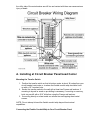
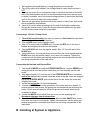
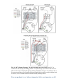
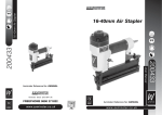
Single Circuit Generator Transfer Switch Models;
HTS15-AUTO SP, HTS15-AUTO DP, HTS15-MAN
Congratulations on your purchase of our Single Circuit Generator Transfer Switch, We
hope this meets and exceeds your expectations. If at anytime you have any questions
please email or call our customer service number for service. Please check out our how
to install videos at our website: http://heezy.com
Tools Needed For Installation
·
·
·
·
·
·
·
·
Power drill
Wire stripper and cutter (10 to 14 gauge)
Screwdrivers (#2 Phillips, ¼” Flat Tip or #2 Square Tip)(Insulated
Recommended)
Voltage Meter
Backup lighting during installation (optional)
A non-contact voltage detector (optional)
Marking pen or pencil (optional)
Tape measure (optional)
Parts List For HTS15
·
·
·
·
·
15 Amp Automatic Transfer Switch w/ conduit whip & wiring
5 - Wire connector nuts
4 - Sheet metal screws
4 - Drywall anchors/screws
1 – Brass Jumper Connector
Safety Symbols & Notices
Heezy LLC & It’s Partners are not responsible for damage or injury caused by
correct or incorrect installation of this transfer switch.
Danger indicates an imminently hazardous situation that, if not
avoided, could result in death or serious injury.
Warning indicates a potentially hazardous situation that, if not
avoided, could result in death or serious injury.
Caution indicates a potentially hazardous situation that, if not
avoided, may result in minor or moderate injury.
Improper installation of the transfer switch could cause damage or personal
injury by electrocution or fire. Installation must be performed by a qualified electrician, or
others knowledgeable of electrical systems, in compliance with all applicable electrical
codes.
Heezy transfer switches covered in this manual should not be used for any
appliances or systems that may exceed the capacity of the product. All transfer switches
meet the NEC (National Electrical Code) for 2011.
Transfer switches are required for use with portable generators by Article 702 of the
2011 National Electrical Code.
SPECIFICATIONS
Product Type
Manufacturer
Model
UPC Code
Maximum Voltage
Number of phases
Maximum Amperage
Maximum Wattage
Case Material
Indoor/Outdoor
Product Height (in.)
Product Width (in.)
Product Depth (in.)
Product Weight (lb.)
Manufacturer Warranty
Return Policy
Manual / Automatic Transfer Switch
Heezy LLC
HTS15-MAN / HTS15-AUTO
Man-799665057046
Auto-799665057060
125 Volts AC
1
15.0 Amps
1875 Watts
Aluminum
Indoor Only
5.5”
3.5”
3.0”
2.0 lb
Lifetime
90-Day
Installation Instructions
There are a few options for installation, usually the most convenient location for
powering the transfer switch is the best option for most installations. We also
recommend locating the transfer switch as close to the back up power source as
possible.
These options are in 3 Sections;
A. Installing at Circuit Breaker Panel/Load Center
B: Installing at System or Appliance
C: Bypassing Neutral Switching (optional)
If installing at the circuit breaker panel, always turn off “main breaker” this is usually at
the top of the breaker panel. Even with the main power switch turned off, the wires on
the utility side of the main breaker are still live and contact with them can cause serious
injury or death.
A. Installing at Circuit Breaker Panel/Load Center
Mounting the Transfer Switch
1. Position the transfer switch so that its bottom center is about 18 inches from your
circuit breaker load center or to where the flexible conduit whip should be lined
up with a 1/2” knockout hole.
2. Anchor the transfer switch to the wall with at least two Powers wall anchors, if
mounting to drywall or wood no pre-drilling is necessary, if mounting on masonry,
brick etc pre-drill with a 3/16” bit before using the Powers wall anchors.
3. If mounting directly on sheet metal use at least two self tapping sheet metal
screws.
NOTE: Do not attempt to bend the flexible conduit whip beyond its structural
capabilities.
Connecting the Flexible Conduit Whip to Your Circuit Breaker Panel
1. Set up battery-powered lighting to clearly illuminate your work area.
2. Turn off the main utility breaker, Use Voltage Meter to check that the power is
OFF
3. Remove the cover of your load center. Keep in mind that the wires on the utility
side of the main breaker are still live and if contacted could cause serious injury
or death. If available, use a non-contact voltage detector to insure that the power
is off on the non-utility side of the main breaker.
4. Remove the appropriate knockout hole in the bottom or side of your load center
with a screwdriver and hammer.
5. Insert all five of the wires extending from the end of the flexible conduit whip
through the knockout hole. Fasten the conduit connector attached to the whip
into the knockout hole using the nut provided.
Connecting a 120 Volt 15 Amp Circuit
1. Turn off the circuit breaker you want to connect to. Disconnect the wire that is
attached to it and leave it off to the side.
2. Find the RED wire from the transfer switch
3. Strip 1/2” from the end of the RED wire. Connect the RED wire to the circuit
breaker and retighten the screw on the breaker.
4. Find the BLACK wire from the transfer switch. Strip 1/2” from the end of the
BLACK wire.
5. Insert both wires—the one previously removed from the circuit breaker and the
BLACK wire from the transfer switch—into a wire nut connecter. Tighten the
connection until the wires start twisting and push the connected wires back into
the wiring compartment of the load center.
Connecting the Neutrals and Ground Wire
1. Find the ALL WHITE wire and the STRIPED WHITE wire and the GREEN wire
among the wires from the transfer switch that you have inserted into the load
center.
2. Strip approximately 1/2” from the end of the STRIPED WHITE wire. Locate the
neutral bar and partially unscrew a terminal screw on the bar. Insert the stripped
end of the STRIPED WHITE wire into the side of the bar under the screw and
retighten the screw.
3. Locate the ground bar. (It should be labeled.)
4. Connect the GREEN wire to the ground bar in the same way as in step #2. In
service entrance load centers, the ground bar and neutral bar are frequently the
same; if this is true and space is limited the ground and neutral wires can be
connected to either.
5. Locate the WHITE wire (neutral) from the circuit you are powering and
disconnect that wire from the neutral bar.
6. Connect the WHITE wire (neutral) from step #5 to the ALL WHITE wire. Insert
both wires into a wire nut connecter. Tighten the connection until the wires start
twisting and push the connected wires back into the wiring compartment of the
load center.
B. Installing at System or Appliance
Mounting the Transfer Switch
1. Position the transfer switch so that the flexible conduit whip will be lined up with
a 1/2” knockout hole.
2. Anchor the transfer switch to the wall/unit with at least two Powers wall anchors,
if mounting to drywall or wood no pre-drilling is necessary, if mounting on
masonry, brick etc pre-drill with a 3/16” bit before using the Powers wall anchors.
3. If mounting directly on sheet metal use at least two self tapping sheet metal
screws.
Connect the Flexible Conduit Whip to the appliance
1. Set up battery-powered lighting to clearly illuminate your work area.
2. Turn off the circuit breaker servicing the appliance.
3. Remove the electrical access or panel cover. If available, use a non-contact
voltage detector or volt meter to insure that the power is off.
4. Remove the appropriate knockout hole in the bottom or side of your appliance
with a screwdriver and hammer.
5. Insert all five of the wires extending from the end of the flexible conduit whip
through the knockout hole. Fasten the conduit connector attached to the whip
into the knockout hole using the nut provided.
Connecting a 120 Volt 15 Amp Circuit
1. Turn off the circuit breaker for the appliance you want to connect to.
2. Locate the electrical junction box/wiring compartment in the appliance, double
check there is no power present with a volt meter or non contact voltage detector.
3. Strip 1/2” from the end of each of the wires coming from the transfer switch.
4. Locate and disconnect the black (hot) wires from the appliance.
5. Find the RED wire from the transfer switch, and the BLACK wire coming from
the circuit breaker powering the appliance from step #4. Insert both wires into a
wire nut connecter. Tighten the connection until the wires start twisting and push
the connected wires back into the wiring compartment.
6. Find the BLACK wire from the transfer switch and the BLACK wire connected to
the appliance, Insert both wires into a wire nut connecter. Tighten the connection
until the wires start twisting and push the connected wires back into the wiring
compartment.
Connecting the Neutrals and Ground Wire
7. Locate and disconnect the WHITE (neutral) wires from the appliance.
8. Connect the WHITE wire (neutral) coming from the circuit breaker to the
STRIPED WHITE wire from the transfer switch. Insert both wires into a wire nut
connecter. Tighten the connection until the wires start twisting and push the
connected wires back into the wiring compartment of the load center.
9. Connect the WHITE wire (neutral) from the appliance to the ALL WHITE wire
from the transfer switch. Insert both wires into a wire nut connecter. Tighten the
connection until the wires start twisting and push the connected wires back into
the wiring compartment of the load center.
10. Connect all the GROUND wires; Insert all the ground (green or bare copper)
wires into a wire nut connecter. Tighten the connection until the wires start
twisting and push the connected wires back into the wiring compartment of the
load center.
C. Bypassing Neutral Switching (optional)
·
·
·
·
·
The Heezy HTS15 transfer switch is equipped to switch both the Hot leg and
Neutral legs of the power from both the utility line power and the generator
power. This is may required for some local codes, particular generators and
some (HE) high efficiency appliances. Bypassing the neutral switching will not
compromise any safety features.
In some circumstances this feature may need to be bypassed for proper
operation for certain types of equipment & generators. Generators with a floating
or non-bonded neutral generally require to have the neutrals tied together
(not-switched) for proper operation.
To check your generator neutral wiring, use a volt/ohm meter and set it to check
for continuity, while the generator is turned off and unplugged from anything
place the probes into the neutral and ground terminals of an outlet plug, on a
120V outlet this would be at the 9 –o’clock and 6-o’clock position, if it beeps or
shows a connection then you have a bonded neutral and don’t need to connect
the neutrals.
If it shows it’s open or not connected then it’s a floating neutral and may require
you to connect them together in the transfer switch if the generator or appliance
has problems operating.
This may become necessary if the appliances being controlled don’t operate
properly or at all on the generator power. This has been the case on some
brands of High Efficiency furnaces.
To bypass the neutral switching
1. If already installed, shut off circuit breaker or main breaker serving the transfer
switch.
2. All the neutrals need to be connected together, this can be done by connecting
all the neutral wires to the neutral bar or connecting together with a wire nut in
the appliance wiring compartment.
3. Another option is to connect all the neutrals together inside the transfer switch.
4. Remove the front cover plate by removing the 4 screws on the top/bottom.
5.
Remove all the white (neutral) wires from the back of the switch. Using the push
on jumper connector (brass colored) connect the 2 white wires together and
place back on the middle connector on the switch and/or relay.
6. NOTE: The white wire w/colored stripe will no longer be used, so it must
removed from the transfer switch and conduit.
7. Place the front cover plate back on and attach with the screws.
After you have completed the steps in Sections A through C, complete the
installation by doing the following:
1. Turn the circuit breaker in your load center/breaker panel back on.
2. Turn on the main breaker.
Operating Instructions
You want your generator to be ready when you need it -- so, it is important to perform the following steps at least
every 6 months:
·
Start and run generator power through your transfer switch circuits.
·
Keep your fuel tank filled with fresh fuel
With your Heezy transfer switch installed, it is not necessary to turn off any of your load center breakers when starting your
generator, even when utility power is fully functional. This is because the double throw break-before- make action of the
transfer switch prevents feeding generator power to the utility and, conversely, prevents feeding utility power back to your
generator.
Transferring from Utility Line Power to Backup
Generator Power in an Emergency
HTS15-AUTO (SP) Standard Power Version;
1. The Auto SP Transfer Switch is normally powered by your Utility line voltage,
when this fails or is interrupted simply start your generator outdoors and let it
warm to a point where it is running evenly.
2. Plug the appropriately sized extension cord into the appropriate receptacle on
your generator.
3. Plug the female end of the extension cord into the Automatic Transfer Switch.
4. The Transfer Switch will automatically switch over from your Utility Line Voltage
to your backup power source.
Transferring back to utility power when power is restored
1. Turn off your generator.
2. Unplug the extension cord.
3. The Auto Transfer Switch will automatically switch back to your Utility Line
Voltage once there is no power present at the Inlet Plug. If your main utility power
comes back on while using your generator the transfer switch will continue to run
through the backup power source until you remove power from the inlet plug.
HTS15-AUTO (DP) Dual Power Version;
1. The Auto DP Transfer Switch is normally powered by your Utility line voltage,
when this fails or is interrupted it will automatically switch over to your back up
power source.
2. Keep the appropriately sized extension cord plugged into your inverter/battery
bank or auto starting generator and into the inlet plug of the transfer switch.
3. It is not necessary to remove this cord unless you want to keep the switch from
automatically being powered by your backup power source.
4. The Transfer Switch will automatically switch over to your Utility Line Voltage
when power has been restored.
HTS15-MAN (Manual Versions)
1. Make sure that the toggle switch on the Transfer Switch is in the MAIN/LINE or
OFF position.
2. Plug the appropriate extension cord into the appropriate receptacle on your
generator.
3. Plug the female end of the extension cord into the Transfer Switch.
4. Start your generator outdoors and let it warm to a point where it is running
evenly.
5. Turn the toggle switch on the transfer switch to the GEN/PLUG position.
Transferring back to utility power when power is restored
1. Move the toggle switch on the Transfer Switch back to the OFF or MAIN/LINE
position.
2. Turn off your generator.
3. Unplug the extension cord.
Wiring Diagrams
The No “BS” Lifetime Warranty; The only warranty that covers it all! Heezy LLC is
committed to developing outstanding products of superior design, performance and value. We
pride ourselves on developing an ongoing, lifelong relationship with you, our consumer. Due to
our extreme confidence in our products and our insatiable desire to deliver only the highest level
of service, we have created the most consumer-friendly warranty there is.
If one our products is ever broken, damaged or fails to work properly, we will
repair or replace it free of charge. Regardless of who broke it. Simple as that! 90
Day No Questions Asked 100% Refund! If your not 100% satisfied with our
product simply return it in the original box within 90 Days of purchase and
receive 100% of your purchase price.
Our “No BS” Lifetime Warranty will cover the repair of all functional aspects of your Heezy
LLC Product for the life of the product. Naturally, our warranty does not cover labor to install or
remove any products, shipping or freight charges, degradable materials components or abusive or
negligent use.
Just call or email us with your issue & we will promptly try to resolve the issue. Call our Service
Center at (415) 754-3399 (9-4 PST) or email ([email protected]) to receive prompt friendly
service. If returning for full refund simply mail back your product with the original packaging to
our address below within 90 Days. No need to call for returns, only if you need service. Thanks!
Heezy LLC
20126 Ballinger Way #275
Shoreline, WA
98155