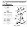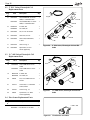
1
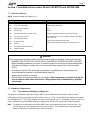
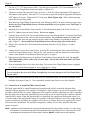
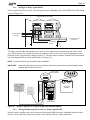
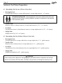
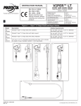
Installation and Operating Data
Installation and
Operation Manual
Jandy® AquaPure™
Electronic Chlorine
Generator
APURE700 and APURE1400
k® RS
n
i
L
a
u
q
A
Exclusive
Plus
Interface
Unions
C
V
P
"
2
w
Ne
H0567500G
LI4011 Rev 7
WARNING
FOR YOUR SAFETY - This product must be installed and serviced by a professional pool/spa
service technician. The procedures in this manual must be followed exactly. Failure to follow
warning notices and instructions may result in property damage, serious injury, or death.
Page 3
Table of Contents
Section 1. Safety Information .......................
4
Section 2. System Description ......................
2.1 Electrical Specifications ...............
5
6
Section 3. Installation Instructions Model
APURE700 and APURE1400 ......
3.1 Materials and Tools ......................
3.2 Plumbing Configurations .............
3.2.1
Recommended Plumbing
Configuration .......................
3.2.2
Alternate Plumbing
Configurations .....................
3.3 Installing APURE700
and APURE1400 Control Center .
3.4 Earth Bonding (Grounding) .........
3.5 Installing the APURE700 and
APURE1400 Cell and Flow/Temp/
Salinity Sensor .............................
3.6 Connection to an AquaLink® RS
Control System.............................
3.6.1
Wiring to a Jandy
AquaLink RS .......................
3.6.2
Wiring Multiple AquaPure
Units to a Jandy AquaLink RS
Section 4. Pool Water Preparation ................
4.1 Determining Pool Size
(m3 of Water) ...............................
4.2 Determining Pool Size
(Gallons of Water) ........................
4.3 Selecting Model Size ...................
4.4 Chemistry You Need to Know .....
4.5 Optimum Pool Water Conditions
4.6 Chlorine Testing ...........................
4.7 Salt (NaCl sodium chloride) ......
4.7.1
What Type of Salt to Use? ...
4.7.2
How Much Salt to Use? .....
4.7.3
How to Add Salt to the Pool?
7
7
7
7
9
11
12
12
14
15
15
16
16
16
17
17
18
18
18
18
18
19
Section 5. Operating Instructions..................
5.1 Using the Front Panel Controls ....
5.2 Reading the Display .....................
5.3 Operation .....................................
5.4 Startup ..........................................
5.4.1
Shocking ..............................
5.4.2
Apply Power ........................
5.5 Operating in Winter......................
5.6 Recommendations ........................
22
22
23
24
25
25
25
26
26
Section 6.
6.1
6.2
6.3
6.4
6.5
User Maintenance Instructions ....
Daily.............................................
Weekly .........................................
Monthly ........................................
Electrolytic Cell Cleaning ............
Flow/Temp/Salinity Sensor
Cleaning .......................................
Winterizing...................................
27
27
27
27
27
Troubleshooting ...........................
Problems and Corrective Action ..
Service Codes...............................
Additional Letter Codes ...............
30
30
33
33
Section 8. Temperature Conversion ..............
34
6.6
Section 7.
7.1
7.2
7.3
Section 9. Exploded Views and
Replacement Kits .........................
9.1 Control Center Replacement Parts
9.2 2” PVC Union, Electrolytic Cell
Replacement Parts ........................
9.3 1½” ABS Union, Electrolytic Cell
Replacement Parts ........................
9.4 Flow Sensor Replacement Parts...
28
29
35
35
36
36
36
Page 4
Section 1. Safety Information
IMPORTANT SAFETY INSTRUCTIONS PERTAINING TO A RISK OF FIRE,
ELECTRIC SHOCK, OR INJURY TO PERSONS
READ AND FOLLOW ALL INSTRUCTIONS
When installing and using this electrical equipment, basic safety precautions should always be followed,
including the following:
WARNING
To reduce the risk of injury, do not permit children to use this product unless they are closely
supervised at all times.
WARNING
When mixing acid with water, ALWAYS ADD ACID TO WATER. NEVER ADD WATER TO ACID.
WARNING
To reduce the risk of electric shock, fire or injury, service should only be attempted by a qualified Pool
Service Professional.
WARNING
Do not operate electrolytic cell without proper flow or water circulation. A buildup of flammable gases
would result in hazardous conditions.
WARNING
Installation must be done in accordance with the National Electric Code (NEC, NFPA-70) and/or any
other applicable local and national installation codes.
RISK OF ELECTRIC SHOCK, FIRE, PERSONAL INJURY, OR DEATH. Connect only to a circuit
that is protected by a ground-fault circuit-interrupter (GFCI). Such a GFCI should be provided by the
installer and should be tested on a routine basis. To test the GFCI, push the test button. The GFCI
should interrupt power. Push the reset button. Power should be restored. If the GFCI fails to operate
in this manner, there is ground current flowing, indicating the possibility of an electric shock. Do not
use this unit. Disconnect this unit and contact a qualified service representative before using.
A green colored terminal (or a wire connector marked “G”, “GR”, “Ground” or “Grounding”) is provided
within the terminal compartment. To reduce risk of electric shock, connect this terminal or connector
to the grounding terminal of your electric service or supply panel with a conductor equivalent in size
to the circuit conductors supplying this equipment.
Power supply must be interconnected with Pool Pump motor power source. This insures the
clorinator and pool pump will turn on and off together.
Use of chemicals other than those recommended may be hazardous. Follow the Chemical
Manufacturers Instructions.
It is recommended that the water Flow/Temp/Salinity Sensor is installed in the same piping as the
electrolytic cell, without any valves or diverters between them. (See page 5 Figure 1).
The Flow/Temp/Salinity Sensor must be mounted as in page 13 Figure 11.
SAVE THESE INSTRUCTIONS
Page 5
Section 2. System Description
Note: Pool Pump and Control Center to
AquaPure Must be Wired to Turn
On and Off Together
Options List
1.
2.
3.
4.
ORP / External Control Interface
ORP / Freeze Control Unit
Pool Pump Timer/AquaLink® RS
Heater
AquaPure
Control
Center
AquaLink RS
Control System or
24 Hour Pool Pump
Timer
Control Signal
from ORP Unit
to ORP Interface
Filter
Flow / Salinity
Sensor
Heater
115 / 230 VAC
Electrical Supply
AquaPure
Cell
To Drain
(Backwash)
Pump
Salt for Pool
Return
to
Pool
From
Pool
Figure 1.
Typical AquaPure Installation With Options
ATTENTION INSTALLER: Various application notes (more detailed instructions) are
available from the Dealer covering installation, operation, maintenance, and plumbing
of the chlorinator system.
The AquaPure uses a process known as electrolysis to produce sodium hypochlorite (liquid chlorine) from
a low concentration of salt added to the pool water. Hypochlorite kills bacteria, oxidizes organic material,
and kills algae then reverts back to salt. The AquaPure then reuses the salt and the process starts over again.
The AquaPure system is comprised of the following three component parts and an optional pool pump timer.
Control Center
The control center converts AC electrical current to a low voltage DC current which
is required by the cell to perform the electrolysis. The control center is connected
with the pool circulation pump electrical source so that the electrolytic cell only
operates when the pool pump is on. The flow portion of the Flow/Temp/Salinity
Sensor is a backup device only.
Electrolytic Cell
The electrolytic cell contains bipolar electrodes which perform the electrolysis and
produce chlorine when energized with DC current. Chlorine is generated as pool
water containing salt passes through the cell. The chlorine production can be varied
by either adjusting the Chlorine Production Level on the control center or by varying
the number of hours the AquaPure is on each day. The AquaPure automatically
cleans the Cell electrodes once every 3 hours. This does not interrupt the
production of Chlorine.
The Flow/Temp/Salinity Sensor only allows the Cell to operate if
there is adequate water flow through the Cell. The salinity portion of the Flow/Temp/
Salinity Sensor detects the level of salt in the pool water. This salt level is displayed
in grams per liter (gpl) on the Liquid Crystal Display (LCD) whenever the salinity
button is pressed. This eliminates the need for manual pool water salinity testing.
Pool Temperature is now available on all models by pressing the Temperature button.
Flow/Salinity/Temperature Sensor
Page 6
A Pool Pump Timer is not included as part of your AquaPure. It is recommended that
a timer or an AquaLink RS control system be used to save on energy and prolong the
service life of your pool pump and the AquaPure.
Pool Pump Timer
2.1 Electrical Specifications
Circuit Protection
2 pole 20 AMP device at the Electrical Panel.
Model APURE700
Model APURE1400
Input:
115 VAC, 50/60 Hz, 1.5 AMPS
230 VAC, 50/60 Hz, 0.75 AMPS
Input:
115 VAC, 50/60 Hz, 2.5 AMPS
230 VAC, 50/60 Hz, 1.25 AMPS
Output:
22-30 VDC @ 3 AMPS maximum
Output:
22-30 VDC @ 6 AMPS maximum
Chlorine:
0.625 lb. / 24 Hr. (283 gm / 24 Hr.)
Chlorine: 1.25 lb. / 24 Hr. (567 gm / 24 Hr.)
External
Control:
ORP/External Control Connector
AquaLink® RS485 Connector
External
Control:
ORP/External Control Connector
AquaLink® RS485 Connector
CAUTION
Factory wired for 230 VAC service. If available electrical service is 115 VAC, the power supply
wiring must be changed to operate on 115 VAC as shown in the wiring diagram below. (Figure 2.)
Us e Co p p e r Co n d u c to rs On ly – Ra te d fo r 90°C Min im u m
Tra n s fo rm e r
Fa c to ry Wire d fo r
230 VAC
Wire Nut Conne ctions
Loa d 1 to Blk
Loa d 2 to Blk/Ye l
Blk/Re d to Blk/Wht
Ribbon Cable
To Back PCB
Stripe
Flow Salinity
Sensor
Test
Switches
Flow
Sensor
Test Points
A to K
Aux Board
R H S
Re -wire d fo r
115 VAC
ORP RED BLK YEL GRN
24 VAC
AquaLink RS
-L
-U
Front PCB
Re ve rse Sid e
From Front
PCB
Stripe
Figure 2.
APURE700 and APURE1400
Ribbon
Ca ble
Test
Points
L to U
A
Transformer
Test Points
Common
Test Points 1 A
1-8
8 B
B
Gre en
Ba c k
DC Cord
22 - 30 VDC
PCB
Black / White
Wire Nut Conne ctions
Loa d 1
Loa d 2
to Blk/Wht a nd Blk/Ye l
to Blk/Re d a nd Blk
Page 7
Section 3. Installation Instructions Model APURE700 and APURE1400
3.1 Materials and Tools
NOTE Salt not included. See pages 18 - 21.
Installation Materials Furnished
Tools Needed for Installation
(1 ea.)
Electrolytic Cell
Tape Measure
(2 ea.)
2” PVC Unions with O-Rings
Phillips & Flathead Screwdrivers
(1 ea.)
PVC Tee for Sensor Mounting
Pliers
(1 ea.)
Roll Teflon Tape
Hacksaw
(1 ea.)
Flow/Temp/Salinity Sensor 16 ft (4.88 m) cable
Voltmeter to determine line voltage of AC wiring to power supply
(1 ea.)
16 ft (4.88 m) DC Power Cord
(1 ea.)
Power Supply/Control Center
Electric Drill Motor and 1/4 “ masonry drill bit for mounting power supply on
block or stucco wall
(4 ea.)
Anchors and Screws
(2 ea.)
Wire Nuts
(1 ea.)
Owner’s Manual - Warranty Information
(1 ea.)
Installation Template
An NSF® approved All Purpose Cleaner Primer
An NSF® approved All Purpose Cement (such as Weld-On 794, 793)
WARNING
When using electrical products, basic precautions should always be followed, including the following:
•
DANGER: RISK OF ELECTRIC SHOCK WHICH CAN RESULT IN SERIOUS INJURY OR DEATH.
Before attempting installation or service, ensure that all power to the device is disconnected/turned
off at the circuit breaker. Connect only to a circuit protected by a ground fault circuit-interrupter
(GFCI).
•
Grounding is required. The unit should be installed by a qualified service representative and
should be properly grounded. (See Earth Bonding, page 12).
•
Install to permit access for servicing.
•
Read Cautions and Important Instructions on page 4. Before attempting any electrical wiring, be
sure to read and follow Safety Instructions. Wiring should only be attempted by a qualified
professional.
3.2 Plumbing Configurations
3.2.1
Recommended Plumbing Configuration
The preferred installation is that the Sensors and Cell are plumbed in the return line to the pool after
(downstream) all the pool equipment (filter, heater, solar, etc.). The Cell and Sensor Tee fitting are designed
to be plumbed into 2” PVC pipe. Adapters can be used for systems with 1.5” plumbing. Figures 3 and 4 on
page 8 illustrate the recommended plumbing configuration, which result in the most reliable operation.
Note
The AquaPure is powered from the LOAD SIDE of the pool circulation pump relay or the time clock. This
ensures that the Cell only operates when the pool pump is ON. The Flow Sensor serves as a protection
device to ensure there is sufficient flow for the cell to operate.
Page 8
Heater
Cell
Sensors
JANDY
Pool
Return
Figure 3.
Spa
Return
Recommended Plumbing Configuration with Cell and Sensors #1, Top View
Jandy Valve Actuator (JVA)
Sensors
AquaPure
Heater
Cell
Mounted
Vertically
Pool
Return
Spa
Return
Ground
Figure 4.
Recommended Plumbing Configuration with Cell and Sensors #2, Side View
Page 9
3.2.2
Alternate Plumbing Configurations
There are alternate plumbing layouts to allow for chlorination of the pool during spa spillover operation,
but prevent over-chlorination of the spa during “spa only” operation (see figures 5 and 6). The configuration
shown in Figure 5 will only chlorinate the pool. Whereas Figure 6 allows chlorination of the pool or spa. If
the AquaPure is controlled by an AquaLink RS, the AquaPure is notified when the AquaLink RS is in Spa
Mode and adjusts to 10% of the AquaLink RS output setting to ensure the spa is not over-chlorinated.
Note
The AquaPure is powered from the LOAD SIDE of the pool circulation pump relay or the time clock. This
ensures that the Cell only operates when the pool pump is ON. The Flow Sensor serves as a protection
device to ensure there is sufficient flow for the Cell to operate.
AquaLink RS Control
System
or Time Clock
AquaPure /
ClorMatic
Cell
Heater
Sensors
JANDY
JANDY
Pool
Return
Figure 5.
Spa
Return
Alternate Plumbing Configuration with Cell and Sensors, Without Spa Bypass for Spillover, Top
View
AquaLink RS Control
System
or Time Clock
Sensors
AquaPure /
ClorMatic
Cell
Heater
Spa
Bypass for
Spillover
JANDY
JANDY
Pool
Return
Figure 6.
Spa
Return
Alternate Plumbing Configuration with Cell and Sensors, With Spa Bypass for Spillover, Top
View
Page 10
WARNING
AVOID HAZARDOUS PLUMBING: Do not mount the Flow/Temp/Salinity Sensor and Cell as shown
in Figures 7 and 8. If a valve is located improperly between the flow/temp/salinity sensor and the
electrolytic cell, it may cause the cell to operate without water flow through the cell which can create a
HAZARDOUS condition.
Sensors
AquaPure
Heater
Pool
Return
Figure 7.
Cell
Mounted
Vertically
Spa
Return
Hazardous Plumbing Configuration with Cell and Sensors, Cell Mounted on Pool Return Line
Sensors
AquaPure
Heater
Pool
Return
Figure 8.
Cell
Mounted
Vertically
Spa
Return
Hazardous Plumbing Configuration with Cell and Sensors, Cell Mounted on Spa Return Line
Page 11
3.3 Installing APURE700 and APURE1400 Control Center
1. Locate the Control Center as close to the pump and filtration system as possible. Make sure that the DC
power cord and the Flow/Temp/Salinity Sensor cable can reach that section of pipe selected for the Cell
and Flow/Temp/Salinity Sensor installation. Do not install the Control Center within 10 ft (3 m) of the
pool edges.
2.
Use hardware provided and mount the control center at eye level. Leave sufficient clearance on all
sides of the chassis backplate. If possible leave a minimum of 9½ inch (241 mm) on the left side.
Position the backplate on the mounting surface. Mark screw centers and drill four ¼ inch (6.35 mm)
holes spaced 10 3/8 inches (264 mm) on the horizontal center and 6 3/8 inches (162 mm) on the vertical
center. Install the anchors (provided) into the mounting surface. See Figure 9.
3.
Install the screws (provided) into the anchors, leaving approximately ¼” of the screw shaft exposed.
Position the backplate keyhole slots over the four mounting screws. Press the control center chassis
down firmly so that the screws are secure in the keyhole slots. Tighten the screws until snug.
4.
Remove the four screws that secure the control center front cover. Remove the front cover.
Install Anchors (4)
and Screws (4) into
mounting surface
Drill two (2) holes
spaced 6 3/8” on the
vertical center.
Drill two (2) holes spaced 10 3/8” on
the horizontal center.
Figure 9.
5.
Lower Chassis Keyhole on
to screws and tighten.
Mounting the Control Center Chassis Backplate
Using two of the four front cover screws, attach the cover to the chassis backplate. Please note that the
chassis backplate has side mounting holes on both sides that allow you to secure the cover to either side
of the backplate while you make all wire connections (see Figure 10).
Front cover secured to
available mounting holes.
Figure 10.
Securing the Control Center Front Cover to the Chassis Backplate
Mounting holes
for front cover.
Page 12
6.
Check source voltage. (All units are factory wired for 230 VAC). In order to use on 115 VAC, the
internal factory wiring of the control center must be changed. (See wiring diagram page 6
Figure 2).
7.
Use #12/3 insulated wire and conduit. Wire control center transformer to pool pump power source.
The control center should be connected to the pump motor switch or automatic timer (Pool Pump
Timer) as shown in the diagram on page 6 Figure 2. The flow portion of the Flow/Temp/Salinity
Sensor is a backup device only. Attach the third wire (Ground) from the electrical panel to the ground
point inside the Control Center. Earth bonding in Section 3.4 must also be accomplished to insure
personal safety and safety of equipment.
3.4 Earth Bonding (Grounding)
A solid, copper # 8 awg (8.4 mm2) wire is recommended for connecting the control center to a Permanent
Earth Ground connection that is acceptable to the local inspection authority. Refer to your local codes for
the acceptable grounding wire gauge. Attach the bonding point located on bottom of the chassis backplate
to a Common Earth Bonding Point. Do not use the AquaPure as the Common Bonding Point. Each piece
of non-AquaPure related pool equipment requiring a ground should be bonded to the Common, Approved
Earth Bonding Point. Never ground pool pump to the chassis backplate.
3.5 Installing the APURE700 and APURE1400 Cell and Flow/Temp/Salinity Sensor
NOTE: Maximum operating Pressure is 517 kPa or 75 PSI - Minimum Flow Rate is 20 GPM (76 LPM).
1.
Be sure pool pump is turned off.
WARNING
ATTENTION INSTALLER: If The Flow/Temp/Salinity Sensor is not installed properly, it may allow
the Cell to operate without water flow. This would cause a buildup of flammable gases resulting in a
HAZARDOUS Condition.
•
Mount as shown in Figure 11 Detail A. This will result in the most reliable operation.
•
The Flow/Temp/Salinity Sensor must be mounted:
(1) in the same line as the Electrolytic Cell.
(2) with no valves or diverters between the Flow/Temp/Salinity Sensor and Cell.
(3) preferably between the Pool Pump and the Cell.
•
Do not mount the Flow/Temp/Salinity Sensor as shown in Detail C of Figure 11. This mounting
position can be HAZARDOUS.
•
Anytime the Flow/Temp/Salinity Sensor is connected or disconnected and reconnected, the AC
power to the unit must be turned off and back on (Cycle Power). If power is not cycled, unreliable
operation of the Flow/Temp/Salinity Sensor will result.
2.
It is recommended that the Flow/Temp/Salinity Sensor and Electrolytic Cell be installed in the pool
return line after the filter and heater. Water passes through the Flow/Temp/Salinity Sensor before the
Cell. The Cell can be installed in either a horizontal (as shown in Figure 12) or a vertical position.
3.
Position the Flow/Temp/Salinity Sensor Tee and Cell in the recommended position (see page 13 Figure
11 Detail A, page 8 Figures 3 and 4, page 9 Figures 5 and 6, and page 5 Figure 1.
4.
Locate a suitable section of pipe, approximately 21 inches (533 mm) long or follow the recommended
plumbing diagrams beginning on page 8, Figures 3, 4, 5, and 6. The Flow/Temp/Salinity Sensor cable
and Cell DC cord must be able to reach from the control center to this section.
Page 13
WARNING
Do not operate the electrolytic cell without water circulation. A buildup of flammable gases will result
in hazardous conditions.
2" PVC Union
Sometimes
Not Covered
Salinity
Studs
2" x 2" x 1-1/2 "
PVC TEE
Cell
From Pump
Teflon
Tape
Temperature
Sensors
Flow Sensor Face
Must Be
Clean
Figure 11.
Connector
Detail B
Not Preferred
Detail C
Flow / Temp / Sal inity
Sensor
Hazardous
Flow/Temp/Salinity Sensor
DC Cord Plug is Connected
to Terminal Studs
PVC Union
O-Ring
Seal
2" PVC Union
and 2" Nut
2" x 2" x 1½"
PVC TEE
Figure 12.
Detail A
Preferred
Cell Installation
PVC Unions and 2" Nuts
2" x 2" x 1½"
PVC Tee
For a 2" pipe, the cutout is 131/8" with the full
unions, without the Tee.
For a 2" pipe, the cutout is 2¼"
for the Tee.
For a 50 mm pipe, the cutout is
77 mm for the Tee.
NOTE Total length of the PVC
Tee is 4¾".
Figure 13.
Pipe Cutout
For a 50 mm pipe, the cutout is 337 mm with the
full unions, without the Tee.
NOTE Total length of the electrolytic cell with the
full unions is 155/8".
Page 14
5.
Cut out a 131/8” (337 mm) section of the 2” (50 mm) pipe to insert the Cell. Cut an additional 2¼” to
insert the Flow/Temp/Salinity Sensor Assembly (see Figure 13).
6.
Clean the cut ends of the pipe and 2 inch x 2 inch x 1½ inch Tee with an appropriate NSF® approved
All Purpose cleaner/primer. Glue the PVC Tee onto the cut pipe ends using an appropriate All Purpose
NSF® approved Cement. Tighten the PVC Union nuts. Hand Tighten Only. Allow sufficient drying
time before pressurizing system.
7.
Wrap the Flow/Temp/Salinity Sensor threads with Teflon tape ONLY (do not use silicone or pipe dope).
Be sure the Flow/Temp/Salinity Sensor (circular metal disks) are free of glue, excess Teflon tape, or
any other debris.
8.
Install the Flow/Temp/Salinity Sensor into the 1½ inch threaded opening of the 2 inch x 2 inch x 1½
inch Tee. Tighten to prevent water leakage. Do not over tighten.
9.
Feed the connector end of the Flow/Temp/Salinity Sensor cable through the DC cord strain relief fitting
located in the bottom of the control center chassis backplate. Be certain the connector is clean and
dry, then plug the cable into the connector on the control center Printed Circuit Board as shown on
page 6 Figure 2. (Do not pull Flow/Temp/Salinity Sensor cable too tight, allow a little slack).
10. Plug the DC cord into the Cell stud terminals protruding from the Cell top. (Plug in - in either
direction).
11. Connect the DC cord to the Control Center. Feed the DC cord through the same strain relief fitting
as the Flow/Temp/Salinity Sensor. Plug the DC cord into the two push-on connectors located on the
control center Printed Circuit Board as shown in Figure 2 on page 6.
12. Tighten strain relief fitting screws for the Flow/Temp/Salinity Sensor and the DC cord. Do not pull
Flow/Temp/Salinity Sensor cable or DC Cord too tight. Allow a little slack cable inside of Control
Center Enclosure.
13. Prior to reattaching front cover, check the wiring. Be sure the Flow/Temp/Salinity Sensor is plugged
in. The DC cord should be plugged in. Also, check the AC wiring.
CAUTION
Do not overtighten the strain relief fitting. Overtightening can cause damage to the Flow/Temp/Salinity
Sensor cable.
14. Plug the ribbon cable attached to the front cover PC board into Printed Circuit Board mounted on the
backplate (See page 6 Figure 2). Now reattach the control center front cover to the backplate.
3.6 Connection to an AquaLink® RS Control System
The Jandy AquaLink RS is a multi-function pool controller and can fully control the function of the
AquaPure chlorine generator. The AquaPure will display JA when a button is pressed at the AquaPure while
the Jandy AquaLink RS is in control. Adjustment of the AquaPure chlorine production rate can be controlled
from the main menu of the Jandy AquaLink RS. Boost mode may be activated from the AquaPure while the
AquaLink RS is online. When the AquaLink RS is in Spa Mode, the AquaPure will adjust the output % to
1/10 (one-tenth) of the AquaLink RS setting. For example, if the AquaLink RS is set to 50% output and the
system is switched to Spa Mode, the AquaPure will switch to 5% output. Refer to the AquaLink RS Owners
Manual for more information. The AquaPure temperature, salinity, service codes, and LED indicators
operate as normal.
NOTE AquaPure Chlorine Generator will communicate with AquaLink RS using firmware versions JJ or later. When
the AquaPure is controlled by the optional Jandy AquaLink RS control system, the % output and hours must
be adjusted from the AquaLink RS control panel. However, BOOST is functional from the AquaPure.
Page 15
3.6.1
Wiring to a Jandy AquaLink RS
In the AquaLink RS Power Center, wire the AquaPure power directly to the LOAD SIDE of the Filter Pump
relay (see Figure 14).
AquaLink RS Power Center
Filter Pump Relay
Aux. 3 Relay
Line 2
Load 2
Line 1
Load 1
To Filter Pump
230 VAC
To AquaPure PCB
(230 VAC)
To Breaker
Panel
Figure 14.
Wiring AquaPure Power to an AquaLink RS Power Center
The Jandy AquaLink RS and AquaPure use a four (4) wire connection to communicate and can be wired
up to 500 feet apart. Any outdoor rated four (4) conductor cable can be used. Locate the appropriate screw
terminals on the circuit board according to Figure 15. Wire the master AquaPure from the red 4-pin terminal
bar to the AquaLink RS red 4-pin terminal bar (see Figure 15).
NOTE The screw terminals are removable to aid in installation.
IMPORTANT
Attach the master AquaPure wires to the like-numbered screw terminals on both the AquaPure and
AquaLink RS as shown in Figure 15.
RED BLK YEL GRN
AquaLink RS
BLK
RED
GRN
YEL
Red, 4-Pin
Terminal Bar
4 3 2 1
Test
Switches
Flow
Sensor
Test Points
A to K
Aux Board
R H S
ORP Red BLK YEL GRN
24 VAC
AquaLink RS
Front PCB
Reverse Side
AquaPure
(Master)
OPTIONAL
or
Jandy
Power Center
Figure 15.
3.6.2
Wiring an AquaPure to an AquaLink RS Control System Network
Wiring Multiple AquaPure Units to a Jandy AquaLink RS
Only the master AquaPure unit can be connected to the AquaLink RS network. Additional AquaPure units
may be wired to the Filter Pump relay, but not to the AquaLink RS red, 4-pin terminal bar.
Page 16
Section 4. Pool Water Preparation
4.1 Determining Pool Size (m3 of Water in Your Pool)
• Rectangular Pools
Average length (meters) x average width (meters) x average depth (meters) = m3 capacity.
ATTENTION INSTALLER: Various application notes (more detailed instructions) are
available from the Dealer covering installation, operation, maintenance, and plumbing
of the chlorinator system.
• Circular Pools
Diameter (meters) x diameter (meters) x average depth (meters) x 0.79 = m3 capacity.
• Oval Pools
Long diameter (meters) x short diameter (meters) x average depth (meters) x 0.79 = m3 capacity.
• Sloping Sides
Multiply total m3 by 0.85 = m3 capacity.
4.2 Determining Pool Size (Gallons of Water in Your Pool)
• Rectangular Pools
Average length (feet) x average width (feet) x average depth (feet) x 7.5 = gallon capacity.
• Circular Pools
Diameter (feet) x diameter (feet) x average depth (feet) x 5.9 = gallon capacity.
• Oval Pools
Long diameter (feet) x short diameter (feet) x average depth (feet) x 5.9 = gallon capacity.
• Sloping Sides
Multiply total gallons by 0.85 = gallon capacity.
CAUTION
Never use dry acid to adjust pH in arid geographic areas with excessive evaporation and minimal
dilution of pool water with fresh water. A buildup of by-products can damage the electrolytic cell.
Page 17
4.3 Selecting Model Size
Model APURE700
Model APURE1400
Chlorine Production
Chlorine Production
283 gm (0.625 lbs) per 24 Hour period.
Residential Pools
567 gm (1.25 lbs) per 24 Hour period.
Residential Pools
One (1) unit per 57 m (up to 15,000 gal) pool
(year round use).
One (1) unit per 114 m3 (up to 30,000 gal) pool
(year round use).
One (1) unit per 66 m3 (up to 17,500 gal) pool
(winterized).
One (1) unit per 132 m3 (up to 35,000 gal) pool
(winterized).
3
Commercial Pools
Check With Manufacturer.
See Commercial Sizing Guide.
Commercial Pools
Check With Manufacturer.
See Commercial Sizing Guide.
4.4 Chemistry You Need to Know
1. Chlorine Stabilizer (cyanuric acid) is needed to maintain proper levels of chlorine. Most unstable
chlorine is destroyed by the UV radiation from the sun within 2 hours. Chlorine stabilizer should be
maintained between 50 - 75 PPM. See Table 3, page 21.
2.
Nitrates can cause extremely high chlorine demands and will deplete chlorine from your swimming
pool. In some cases Nitrates may even lower your chlorine levels to zero. Your local pool professional
can test for Nitrates. Make sure Nitrates are not present in your pool.
3.
Metals (some metals) can cause loss of chlorine. Also, metals can stain your pool. Have your local
pool professional check for metals and recommend methods of removal.
4.
Chloramines should not be present in pool water. When organic materials combine with Free
Chlorine, Chloramines are formed. This ties up the Free Chlorine in your pool and does not allow
the chlorine in your pool to disinfect. Chloramines also cloud pool water and burn the eyes. (Super
Chlorinate (shock) to remove Chloramines at the initial startup of the pool).
5.
Super Chlorination (Shocking) burns out the organic material that has combined with chlorine.
This frees the chlorine for sanitizing. This is accomplished by raising the chlorine level quickly and
dramatically. When the chlorine level is raised to 5 - 15 PPM the pool water is said to have been Super
Chlorinated (shocked). As pool water is continuously passed through the AquaPure Electrolytic Cell,
all pool water inside the cell is being Super Chlorinated. When the AquaPure is used on pools the pool
water sparkles and does not burn the eyes because of the absence of Chloramines.
NOTE On initial startup of a pool, it is best to Super Chlorinate from an outside source, i.e., use a shock treatment
available at your local pool supplier.
6.
pH produced by the AquaPure is close to Neutral pH. However, other factors usually cause the pH
of the pool water to rise. Therefore, the pH in a pool chlorinated by the AquaPure tends to stabilize
at approximately 7.8. This is within NSPI standards. If the pool pH rises above 7.8 have a pool
professional test to see if other factors such as high Calcium Hardness or Total Alkalinity are the cause
and then balance accordingly.
7.
Total Dissolved Solids (TDS) Adding salt to pool water will raise the TDS level. While this does not
adversely affect the pool water chemistry or clarity, the pool water professional testing for TDS must
be made aware salt has been added for the AquaPure system. The individual performing the TDS test
will then subtract the salinity level to arrive at the correct TDS level.
8.
New Pool Water in a recently filled or newly refinished pool may contain undesirable matter. This
undesirable matter could interfere with the AquaPure’s ability to chlorinate properly. Make sure the
water is tested by a pool professional and properly balanced before turning on the AquaPure.
Page 18
4.5 Optimum Pool Water Conditions
In accordance with National Spa and Pool Institute (NSPI) standards, we recommend the following water
balance conditions be maintained on an on-going basis to protect the pool finish and equipment and
ensure the pleasing appearance of the water. The AquaPure is warranted to operate properly only if these
conditions are met.
Free Chlorine
1.0 - 3.0 PPM. Above 3.0 PPM may cause corrosion of
pool metals.
Combined Chlorine (Chloramines) None (Super Chlorinate to remove all Chloramines).
pH
7.2 - 7.8 (USE MURIATIC ACID to lower pH and Soda Ash
to raise pH).
Chlorine Stabilizer (Cyanuric Acid)
50 - 75 PPM
Total Alkalinity
80 - 120 PPM
Calcium Hardness
150 - 400 PPM
Metals (Copper, Iron, Manganese)
Nitrates
None
None
4.6 Chlorine Testing
It is recommended that chlorine test samples be taken from two places. Compare the samples. A higher
level should be found at the pool return line. The higher level at the pool return line indicates the AquaPure
is producing chlorine.
1.
At the pool return line.
2.
18 inches (457 mm) below the surface and well away from the pool return line.
4.7 Salt (NaCl sodium chloride)
4.7.1
What Type of Salt to Use?
• The purer the salt the better the life and performance of the electrolytic cell. Use a salt that is at least
99.8% pure NaCl. The preferred salt is an evaporated, granulated, food quality, non-iodized salt.
Consult your salt supplier.
• Avoid using salt with anti-caking agents (sodium ferrocyanide, also known as YPS or yellow prussiate
of soda) that could cause some discoloration of fittings and surface finishes in pool.
• Water conditioning salt pellets are compressed forms of evaporated salt and may be used but will take
longer to dissolve.
• Do Not use calcium chloride as a source of salt. (Use sodium chloride only).
• Do Not use Rock salt (insoluble impurities mixed with the rock salt can shorten the life of the unit).
4.7.2
How Much Salt to Use?
Use Table 1 on page 20 to determine how much salt will be needed. Most pools contain some salt
depending on the water source and chemicals used for sanitizing. If the AquaPure has not been wired
and turned on yet, a hand held meter calibrated for NaCl (salt) can be used to determine the existing salt
concentration of the water. If the AquaPure is wired in (connected), use it to determine the salinity.
Page 19
Turn the Chlorine Production down to 00% by pressing the arrow button A on front of the control center.
Operating the unit above 00% production without salt will damage Cell. The Salinity button C on the
AquaPure can be used to determine salinity in the case of a new pool installation, or a complete water
change so long as the Chlorine Production is set to 00%. See page 25, Section 5.4.2, step 2.
• 3.0 to 3.5 gpl of salt is recommended for optimum water conditions.
• Low salt concentration below 2.0 gpl will cause premature cell failure.
• High salt concentration above 4.0 gpl may damage the control center.
• High salt concentration above 6.0 gpl may cause corrosion damage to pool fixtures.
NOTE Should too much salt be inadvertently added to the pool see “Troubleshooting” page 30.
NOTE To convert gpl (grams per liter) of a salt solution to PPM (Parts Per Million) of a salt solution multiply by 1000,
i.e., 3.0 gpl salt X 1000 = 3000 PPM salt.
4.7.3
How to Add Salt to the Pool?
1.
Turn on pump to circulate pool water.
2.
IMPORTANT - Turn the AquaPure off by pressing the arrow button A and setting CHLORINE
PRODUCTION Rate to 00%.
3.
Determine amount of salt from the following charts.
4.
Broadcast or spread the salt into the outer perimeter of the pool, or into the shallow end of the pool for
quick and even distribution.
5.
To avoid clogging the filter or damaging control center and pump, do not add salt through the
skimmer, main drain, or surge tank.
6.
Brush the pool bottom and allow water to circulate for 24 hours to dissolve completely and mix evenly
with the pool water.
7.
After 24 hours, verify correct salt reading.
8.
Turn on the AquaPure and set to desired Production rate (Press arrow button B ).
NOTE New Pool Construction The AquaPure hardware can be installed during new pool construction. However,
it is recommended to wait at least 4 weeks to add salt to a new, plaster pool. The addition of salt to a pool
before the plaster is cured may causing pitting, and is dependent on water hardness, temperature, and pH
levels. Therefore, 4 weeks is a safe amount of time to wait prior to dissolving salt in the pool, followed by 24
hour filtering and finally activating the AquaPure cell to generate chlorine.
Page 20
Table 1.
Salt
Conc.
Before
Addition
0.00 g/L
0.25 g/L
0.50 g/L
0.75 g/L
1.00 g/L
1.25 g/L
1.50 g/L
1.75 g/L
2.00 g/L
2.25 g/L
2.50 g/L
2.75 g/L
Approximate Pounds (kg) of Salt Needed to Obtain 3.0 gpl (3,000 PPM) in Pool
Pool
Size
38 m3
(10,000)
45 m3
(12,000)
53 m3
(14,000)
60 m3
(16,000)
68 m3
(18,000)
76 m3
(20,000)
(US gallons)
83 m3
(22,000)
91 m3
(24,000)
113 kg
(250 lbs)
104 kg
(230lbs)
95 kg
(210 lbs)
86 kg
(190 lbs)
75 kg
(165 lbs)
66 kg
(145 lbs)
57 kg
(125 lbs)
48 kg
(105 lbs)
39 kg
(85 lbs)
136 kg
(300 lbs)
127 kg
(280 lbs)
113 kg
(250 lbs)
104 kg
(230 lbs)
91 kg
(200 lbs)
79 kg
(175 lbs)
68 kg
(150 lbs)
59 kg
(130 lbs)
45 kg
(100 lbs)
159 kg
(350 lbs)
145 kg
(320 lbs)
134 kg
(295 lbs)
122 kg
(270 lbs)
104 kg
(230 lbs)
91 kg
(200 lbs)
79 kg
(175 lbs)
68 kg
(150 lbs)
54 kg
(120 lbs)
181 kg
(400 lbs)
168 kg
(370 lbs)
154 kg
(340 lbs)
136 kg
(300 lbs)
120 kg
(265 lbs)
104 kg
(230 lbs)
91 kg
(200 lbs)
77 kg
(170 lbs)
63 kg
(140 lbs)
204 kg
(450 lbs)
188 kg
(415 lbs)
172 kg
(380 lbs)
154 kg
(340 lbs)
136 kg
(300 lbs)
118 kg
(260 lbs)
102 kg
(225 lbs)
86 kg
(190 lbs)
68 kg
(150 lbs)
227 kg
(500 lbs)
209 kg
(460 lbs)
191 kg
(420 lbs)
172 kg
(380 lbs)
150 kg
(330 lbs)
132 kg
(290 lbs)
113 kg
(250 lbs)
95 kg
(210 lbs)
77 kg
(170 lbs)
249 kg
(550 lbs)
231 kg
(510 lbs)
209 kg
(460 lbs)
191 kg
(420 lbs)
163 kg
(360 lbs)
145 kg
(320 lbs)
125 kg
(275 lbs)
104 kg
(230 lbs)
86 kg
(190 lbs)
27 kg
(60 lbs)
18 kg
(40 lbs)
9 kg
(20 lbs)
32 kg
(70 lbs)
23 kg
(50 lbs)
11 kg
(25 lbs)
39 kg
(85 lbs)
27 kg
(60 lbs)
14 kg
(30 lbs)
45 kg
(100 lbs)
29 kg
(65 lbs)
14 kg
(30 lbs)
50 kg
(110 lbs)
32 kg
(70 lbs)
18 kg
(40 lbs)
54 kg
(120 lbs)
36 kg
(80 lbs)
18 kg
(40 lbs)
59 kg
(130 lbs)
41 kg
(90 lbs)
20 kg
(45 lbs)
98 m3
(26,000)
106 m3
(28,000)
272 kg
(600 lbs)
249 kg
(550 lbs)
229 kg
(505 lbs)
209 kg
(460 lbs)
181 kg
(400 lbs)
159 kg
(350 lbs)
136 kg
(300 lbs)
113 kg
(250 lbs)
93 kg
(205 lbs)
295 kg
(650 lbs)
272 kg
(600 lbs)
247 kg
(545 lbs)
225 kg
(495 lbs)
195 kg
(430 lbs)
172 kg
(380 lbs)
147 kg
(325 lbs)
125 kg
(275 lbs)
100 kg
(220 lbs)
318 kg
(700 lbs)
293 kg
(645 lbs)
268 kg
(590 lbs)
240 kg
(530 lbs)
209 kg
(460 lbs)
186 kg
(410 lbs)
159 kg
(350 lbs)
134 kg
(295lbs)
109 kg
(240 lbs)
340 kg
(750 lbs)
313 kg
(690 lbs)
286 kg
(630 lbs)
259 kg
(570 lbs)
225 kg
(495 lbs)
197 kg
(435 lbs)
170 kg
(375 lbs)
143 kg
(315 lbs)
116 kg
(255 lbs)
66 kg
(145 lbs)
45 kg
(100 lbs)
23 kg
(50 lbs)
73 kg
(160 lbs)
48 kg
(105 lbs)
23 kg
(50 lbs)
76 kg
(168 lbs)
50 kg
(110 lbs)
27 kg
(60 lbs)
82 kg
(180 lbs)
54 kg
(120 lbs)
27 kg
(60 lbs)
NOTE Add salt as required to maintain 3.0 gpl concentration
IMPORTANT
Add 1.25 lbs (0.57 kg) of Stabilizer per 50 lbs (22.7 kg) of Salt.
Table 2.
Approximate Pounds (kg) of Salt Needed to Maintain 3.0 gpl (3,000 PPM)
Salt Concentration. Before
Addition
Salt Addition Required
per 1000 gallon pool capacity
Salt Concentration Before
Addition
Salt Addition Required
per 1000 gallon pool capacity
0.0 gpl
25.6 lbs
(11.6 kg)
1.5 gpl
12.8 lbs
(5.8 kg)
0.3 gpl
23.5 lbs
(10.7 kg)
1.8 gpl
10.7 lbs
(4.8 kg)
0.5 gpl
21.4 lbs
(9.7 kg)
2.0 gpl
8.5 lbs
(3.9 kg)
0.8 gpl
19.2 lbs
(8.7 kg)
2.3 gpl
6.4 lbs
(2.9 kg)
1.0 gpl
17.1 lbs
(7.8 kg)
2.5 gpl
4.2 lbs
(1.9 kg)
1.3 gpl
15 lbs
(6.8 kg)
2.8 gpl
2.2 lbs
(1 kg)
113 m3
(30,000)
Page 21
Table 3.
Approximate Amount of Chlorine Stabilizer (Cyanuric Acid) Needed to Obtain 75 PPM
38 m3
(10,000)
45 m3
(12,000)
53 m3
(14,000)
60 m3
(16,000)
Pool
68 m3
(18,000)
Size
76 m3
(20,000)
(US gallons)
83 m3
91 m3
(22,000)
(24,000)
0.00 PPM
2.8 kg
(6.25 lbs)
3.4 kg
(7.50 lbs)
4 kg
(8.75 lbs)
4.5 kg
(10.0 lbs)
5 kg
(11.25lb)
5.7 kg
(12.5 lbs)
6.2 kg
(13.75 lbs)
10 PPM
2.5 kg
(5.40 lbs)
2.9 kg
(6.50 lbs)
3.5 kg
(7.60 lbs)
3.9 kg
(8.60 lbs)
4.4 kg
(9.75 lbs)
5 kg
(10.8 lbs)
20 PPM
2 kg
(4.60 lbs)
2.5 kg
(5.50 lbs)
2.9 kg
(6.40 lbs)
3.3 kg
(7.30 lbs)
3.7 kg
(8.25 lbs)
30 PPM
1.7 kg
(3.75 lbs)
2 kg
(4.50 lbs)
2.4 kg
(5.25 lbs)
2.7 kg
(6.00 lbs)
40 PPM
1.3 kg
(2.90 lbs)
1.6 kg
(3.50 lbs)
1.8 kg
(4.00 lbs)
50 PPM
1 kg
(2.00 lbs)
1.1 kg
(2.50 lbs)
60 PPM
0.5 kg
(1.25 lbs)
70 PPM
75 PPM
Stabilizer
Level
Before
Addition
98 m3
(26,000)
106 m3
(28,000)
113 m3
(30,000)
6.8 kg
(15.0 lbs)
7.4 kg
(16.3 lbs)
7.9 kg
(17.5 lbs)
8.5 kg
(18.75 lbs)
5.4 kg
(11.90 lbs)
5.8 kg
(12.9 lbs)
6.3 kg
(14.0 lbs)
6.9 kg
(15.2 lbs)
7.4 kg
(16.25 lbs)
4.1 kg
(9.20 lbs)
4.5 kg
(10.0 lbs)
4.9 kg
(10.9 lbs)
5.4 kg
(11.9 lbs)
5.8 kg
(12.8 lbs)
6.2 kg
(13.75 lbs)
3 kg
(6.75 lbs)
3.4 kg
(7.50 lbs)
3.7 kg
(8.25 lbs)
4 kg
(9.00 lbs)
4.4 kg
(9.75 lbs)
4.8 kg
(10.5 lbs)
5.3 kg
(11.75 lbs)
2 kg
(4.60 lbs)
2.4 kg
(5.25 lbs)
2.6 kg
(5.80 lbs)
2.9 kg
(6.40 lbs)
3.1 kg
(6.90 lbs)
3.4 kg
(7.58 lbs)
3.7 kg
(8.20 lbs)
4 kg
(8.75 lbs)
1.3 kg
(2.90 lbs)
1.5 kg
(3.30 lbs)
1.7 kg
(3.75 lbs)
1.9 kg
(4.10 lbs)
2 kg
(4.60 lbs)
2.2 kg
(4.90 lbs)
2.4 kg
(5.40 lbs)
2.6 kg
(5.80 lbs)
2.8 kg
(6.25 lbs)
0.7 kg
(1.50 lbs)
0.8 kg
(1.75 lbs)
1 kg
(2.00 lbs)
1 kg
(2.25 lbs)
1.1 kg
(2.50 lbs)
1.2 kg
(2.75 lbs)
1.4 kg
(3.00 lbs)
1.5 kg
(3.25 lbs)
1.6 kg
(3.50 lbs)
1.7 kg
(3.75 lbs)
0.2 kg
(0.40 lbs)
0.2 kg
(0.50 lbs)
0.3 kg
(0.60 lbs)
0.3 kg
(0.66 lbs)
0.3 kg
(0.75 lbs)
0.4 kg
(0.80 lbs)
0.4 kg
(0.90 lbs)
0.4 kg
(1.00 lbs)
0.5 kg
(1.10 lbs)
0.5 kg
(1.20 lbs)
0.6 kg
(1.25 lbs)
0 kg
(0.0 lbs)
0 kg
(0.0 lbs)
0 kg
(0.0 lbs)
0 kg
(0.0 lbs)
0 kg
(0.0 lbs)
0 kg
(0.0 lbs)
0 kg
(0.0 lbs)
0 kg
(0.0 lbs)
0 kg
(0.0 lbs)
0 kg
(0.0 lbs)
0 kg
(0.0 lbs)
NOTE Add 1.25 lbs (0.57 kg) Chlorine Stabilizer to the pool every time 50 lbs (22.7 kg) of Salt is added to the pool.
The Stabilizer reading should be maintained at 75 PPM.
Page 22
Section 5. Operating Instructions
DIRECTIONS FOR ADDING SALT
1.
2.
Broadcast or Spread Salt into Shallow End of Pool. Do Not Add Salt through
Skimmers, Main Drain or Surge Tank.
Set Unit to "00" % for 24 Hours. The AquaPure must read "00" for 24 hours
after the salt has been added and circulated in the pool.
Boost - 24 Hour 100% Chlorine Production Cycle - Refer to Manual
- - - - To Enter Boost Mode Press and Hold "Temperature" Button for 10 Seconds
Pool Temperature - Temperature of Pool Water at Flow Sensor
CELL ON - Making Chlorine
CELL RESTING - Off Portion of Chlorine Production Cycle
FLOW - Water Flow Present
CELL REVERSING - Automatic Cleaning Cycle in Progress
ADD SALT - Salinity Should be 3.0 - 3.5 Grams / Liter
SERVICE - Refer to Manual - - - - To Silence Audible Service Alarm Press and Hold "Salinity" Button for 5 Seconds
CELL ON
CELL RESTING
FLOW
CHLORINE
PRODUCTION RATE
A
B
C
D
CELL REVERSING
ADD SALT
SERVICE
?
Power On
Figure 16.
Salinity
?
Pool
Temperature
- Boost -
Control Center Front Panel
5.1 Using the Front Panel Controls
NOTE With the exception of Boost, the front panel buttons can not be used when the AquaPure is controlled by the
AquaLink RS. If arrow button A or arrow button B is pressed, JA in the AquaPure display indicates that the
AquaLink RS is controlling the AquaPure and desired output percentages.
Chlorine Production Rate
(more or less) Adjustment
Salinity
Boost
Pressing the arrow button A or arrow button B will change the
CHLORINE PRODUCTION in 1% increments. Generally,
adjustments to production should be made in 10% increments.
Press the Salinity button C to check the salinity of the water in pool.
Press and hold the Temperature button D for 10 seconds to enter the
Boost mode (Note ‘bo’ will flash intermittently). Boost can be used to
set chlorine production to maximum (100%) for 24 hours of operation.
After 24 hours of chlorinator run time, chlorine production will return
to previous setting. To clear the Boost mode, press and hold the
Temperature button again for 10 seconds.
NOTE When a pool pump timer is used to limit chlorinator run time, the 24 hours will only count down when the
clorinator is on.
Temperature
Press the Temperature button D to check the pool water temperature.
Temperature measurements can be displayed in either Fahrenheit or
Celsius. For more information, see Section 8, Temperature Conversion.
Page 23
5.2 Reading the Display
Cell On
Cell Resting
The CELL ON indicator shows that the cell has been turned on by the
control center. Some reasons for the CELL ON indicator not being on
during normal operation, are: CHLORINE PRODUCTION set to 00%,
CHLORINE PRODUCTION set to less than 100% and Cell Resting
appears during cell rest period, NO FLOW condition, two minutes before
automatic cleaning cycle, Low temperature cut off has been activated, or
a service related problem such as a salinity level below 2.0 gpl or salinity
level too high.
During the Normal chlorine production cycle when the unit is set for
less than 100% the cell will periodically rest, i.e., not make chlorine.
The CELL RESTING indicator shows that the cell has been turned off by
the control center. The reason for the CELL RESTING indicator, during
normal operation, is CHLORINE PRODUCTION set to less than 100%.
Flow or No Flow Indication
When the control center determines that water is flowing past the Flow/
Temp/Salinity Sensor, the FLOW indicator is displayed. When no flow is
detected, the NO FLOW is displayed and the cell is turned off.
Cell Reversing
The automatic cleaning cycle of the AquaPure is in progress. The
cleaning cycle is factory set and cannot be adjusted. Cell Reversing does
not interrupt the production of Chlorine.
Salinity
Salinity is displayed along with the gpl (grams per liter) indicator, when
the Salinity button is depressed. If a reading of HH appears, the salinity
is above 4.5 to 6.5 gpl (depending on pool temperature) and is too high to
measure correctly (at normal temperatures). Maintain Salinity between
3.0 and 3.5 gpl. See pages 18 through 21.
Add Salt
The ADD SALT indicator comes on when the Flow/Temp/Salinity Sensor
determines that the salinity level of the pool water is too low. Maintain
Salinity between 3.0 and 3.5 gpl.
Service and Service Code
The SERVICE indicator will turn on whenever the AquaPure detects a
problem that requires attention. The SERVICE indicator is accompanied
by a service code displayed on the front panel, displayed as a 3 digit
code. The service code(s) are displayed twice per minute with an audible
alarm.
NOTE See “Service Codes” page 33. Problems can range from insufficient salinity to the DC cord not connected.
See troubleshooting.
Audible Alarm
An audible alarm (beep) sounds once per hour, and only for the first
service code when a Service condition is detected. The Alarm can be
cleared by pressing and holding the Salinity button C for 5 seconds. The
audible alarm can be cleared for 24 hours or until the power to the unit
is turned off and back on whichever comes first. However, the audible
alarm will return if a new problem is detected.
NOTE The audible alarm can be permanently disabled by removing the blue jumper from J10 on the control
center front cover PCB.
Page 24
Beeper Control
Beeper operation and volume control can be adjusted.
To adjust volume control, press and hold the TEMPERATURE button
for 15 seconds. The system will beep once when pressed, once after 10
seconds and once after 15 seconds. Release the key after the third beep.
Press the SALINITY button within 5 seconds to enter the temperature
change screen.
The system will display a ‘1’ followed by ‘F’ or ‘C’. Press the
TEMPERATURE button to move to the second parameter screen. The
screen will display a 0, and the beeper volume will be fully reduced. The
system will occasionally show a ‘2’ to display the screen number.
Press the arrow button B to increase the volume and the arrow button
A to reduce the volume. The volume increments from 0 to 100 in 20
steps. After each press of the arrow buttons, the beeper will activate to
demonstrate the current volume level.
When the beeper volume has been adjusted to the desired setting, press
the SALINITY button to confirm the new beeper volume setting. The
change will be stored in permanent memory.
If you do not wish to keep the change, wait 5 seconds, and the change
screen will ‘time out’ and return to normal operation without keeping
any changes to the system. Any changes made to the beeper volume will
NOT be saved if this occurs.
The Boost cycle is normally activated after 10 seconds, however, if the
key is held down until after the third beep at 15 seconds, the Boost mode
will not be changed.
5.3 Operation
CAUTION
Before attempting to operate refer to page 16 - Pool Water Preparation. Also, do not adjust Chlorine
production above 00% until it is certain that salt has been dissolved in pool. Operating without salt
will damage Electrolytic Cell.
Use of an external Pool Pump Timer is not required. The AquaPure is designed to supply a sufficient
amount of chlorine to sanitize pool water on a daily basis. If the AquaPure is operated 24 hours a day at
100%, more chlorine would be generated than would be needed by most pools (1-3 PPM). The AquaPure
has its own internal timer which cycles the electrolytic cell on and off depending on what percent the
Chlorine Production is set. For instance, at 100% the cell works all the time. When set at 90%, the cell is
allowed to rest 10% of the time prolonging cell life. In order to fine tune the AquaPure to any size pool just
increase or decrease the Chlorine Production from 1% to 100%. (see “Apply Power” Section 5.4.2, page 25,
steps 1-5 )
NOTE When the AquaPure is controlled by the AquaLink RS, Chlorine Production can be adjusted in 5% increments.
• Check Chlorine Level on a regular basis and adjust AquaPure accordingly.
Page 25
If you use a Pool Pump Timer The National Spa and Pool Institute (NSPI) recommends that all water in
a residential pool pass through the filtration system at least once every 12 hours (referred to as pool water
turnover). However, many factors have an effect on actual pump and filter system run times. Pool size,
source of water, direct sun light, indoor/outdoor, screened/unscreened, filtration system, cold or hot weather,
swimmer load, rain, organic debris, algae, etc., are all factors which contribute to either more or less pool
pump and filter system run times. Because of these differences, it is extremely difficult to set an initial run
time (starting point) for the pool pump and chlorinating system.
Try initially setting the Pool Pump Timer to 12 hours. It will take a few days to get just the right pool
pump operating time. Adjust accordingly using the steps listed below ( Section 5.4.2, steps 1-5 ). When
the AquaPure is wired with a Pool Pump Timer (See page 6 Figure 2) results will vary greatly from one
pool installation to the next, so this should be discussed with either the pool builder or the local pool
professional. The key points are:
• Operate pool pump at least the minimum time needed for good filtration.
• The Pool Pump Timer reduces energy consumption.
NOTE Exception - For Cold Weather Operation: If the AquaPure is run 24 hours a day through the winter, extremely
cold water temperatures can effect Cell life. Sometimes it will be necessary to run the AquaPure at a very low
production rate of 10% to 20% or to turn the unit off. See winterizing on page 29.
5.4 Startup
5.4.1
Shocking
Shocking (Super Chlorination) is recommended before pool startup. Start out with good pool water
from the beginning. The AquaPure will build up a sufficient level of chlorine for sanitation in several hours.
However, if pool water has a high demand from the startup the AquaPure will not be able to produce enough
chlorine to reach break point chlorination. So, it is best to super chlorinate from an outside source at the
time of pool startup. Then, wait until the chlorine level has returned to 1 to 3 PPM before turning on the
AquaPure.
5.4.2
Apply Power
1.
Turn on the pool pump switch or Pool Pump Timer. When the AquaPure is first turned on (cold),
the unit will beep. Next it will self-calibrate the Flow/Temp/Salinity Sensor. After going through an
internal test and calibration, the LCD will display the current setting for Chlorine Production (00% to
100%). During the calibration period “Wait” will appear. “Wait” means the unit is self calibrating and
doing internal testing. This usually takes less than 6 minutes.
2.
Check salinity level by pressing the Salinity button. It should read between 3.0 gpl and 3.5 gpl. If it
does not then press the Salinity button two or three more times until the salinity reading stabilizes.
NOTE If still less than 3.0 gpl refer to pages 18 through 20 and adjust salt level. (Maintain the Recommended
Salinity Level of 3.0 to 3.5 gpl). If salinity is below 2.0 gpl the AquaPure will automatically turn the cell off
until the salinity is raised above 2.0 gpl, since operating with low salt will damage Cell. Likewise, if salinity is
above the range of measurement the AquaPure will automatically turn the cell off until the salinity is lowered
to a measurable level, since operating with high salt will damage the control center. If salinity is greater than
3.5 gpl, see Troubleshooting, page 30.
3.
Adjust the Chlorine Production to 50% by pressing the arrow button B.
Page 26
4.
After 24 hours, use a reliable test kit to test the pool water for free active chlorine. The ideal range to
maintain is 1-3 PPM. If the chlorine content of the pool water is too low, increase chlorine production
by pressing the arrow button B. If the chlorine content of the water is too high, Decrease chlorine
production by pressing the arrow button A. Adjust in 10% increments initially then in smaller
increments as the correct chlorine level is approached.
5.
Due to a varying chlorine demand of pool water, it may take a few days to determine the correct pool
pump operating time and chlorine production percentage setting for your pool. Continue adjusting
as necessary, allowing 24 hours between adjustments until the chlorine content of the pool water has
stabilized at 1-3 PPM.
5.5 Operating in Winter
See Winterizing on Page 29.
5.6 Recommendations
DO List
• Read and keep your manual in a safe place.
• Increase Chlorine Production before party time and return to normal afterwards.
• Increase Chlorine Production when temperature goes up.
• Increase Chlorine Production when number of guests goes up.
• Use Stabilizer (Cyanuric Acid) to Stabilize Chlorine in Pool.
• Mount Control Center in shade or out of the direct sunlight whenever possible.
• Decrease Production when temperature goes down. Fall/winter etc.
• Take Pool water sample to Pool Professional once per month.
DON’T List
• Do not get fertilizer in your pool. Fertilizers contain nitrates which cause a high chlorine demand on
pool water.
• Never use dry acid to adjust pH in arid geographic areas with excessive evaporation and minimal
dilution of pool water with fresh water. A build up of by products can damage the electrolytic cell.
• Do not add any pool water balancing chemicals (including salt) unless the AquaPure is turned off.
• Do not let Chlorine Stabilizer drop below 50 PPM.
• Do not add salt without first checking the pool salinity level. Too much salt can disable and possibly
damage the chlorinator.
Page 27
Section 6. User Maintenance Instructions
The following information describe how to care for your AquaPure.
6.1 Daily
None.
6.2 Weekly
1. Chlorine Test. Test pool water chlorine level with a reliable test kit. Maintain ideal range by
adjusting the AquaPure chlorine production rate as discussed on pages 25 through 26 steps 3, 4, and 5.
Recommended Free Chlorine is 1-3 PPM.
NOTE It is recommended that chlorine test samples be taken from two places, one at the pool return line, the other
well away from the pool return line. Compare the samples. A higher level should be found at the pool return
line. The higher level at the pool return line indicates the AquaPure is producing chlorine.
2.
pH Level Test. Test the pH level of your pool with a test kit. If necessary, adjust according to your
pool professional’s recommendations. NSPI standard of 7.2 - 7.8 is recommended.
CAUTION
Never use dry acid to adjust pH in arid geographic areas with excessive evaporation and minimal
dilution of pool water with fresh water. A build up of by products can damage the electrolytic cell.
6.3 Monthly
1. Salt Level Test. Test pool water salt level by depressing the Salinity button C and reading the LCD
located on the front cover of the AquaPure control center. Maintain the ideal range of 3.0-3.5 gpl for
optimum performance of the AquaPure. If additional salt is required, follow the procedures and charts
described on pages 18 through 21. If salt level does not rise after 24 hours, see Troubleshooting on
page 30.
2.
Pool Water Sample. Take water sample to local pool store for testing.
3.
Total Alkalinity Test. Test pool water for total alkalinity with a test kit. Adjust according to your pool
professional’s recommendations. 80-120 PPM NSPI Standard.
4.
Stabilizer (Cyanuric Acid). Test pool water stabilizer (cyanuric acid) level using a test kit or by having
a water sample tested by a pool professional. Maintain ideal range of 50-75 PPM. Follow your pool
professional’s recommendations.
5.
Calcium Hardness. Test pool water for calcium hardness level using test kit or by having a water
sample tested by a pool professional. If necessary, adjust according to your pool professional’s
recommendations. NSPI standard of 150-400 PPM is recommended.
6.
Metals Test. It is recommended that the pool water be tested periodically for the presence of metals
such as copper, iron, and manganese. These metals should not be present in the pool water. If those
metals are present, contact the local pool professional.
6.4 Electrolytic Cell Cleaning - As Needed
1. Automatic Cleaning. The control center has an automatic cell cleaning feature (Cell Reversing) that
removes scale deposits from the electrolytic cell.
NOTE Automatic Cleaning does not interrupt Chlorine Production.
Page 28
“Scale” is a white crusty deposit that forms in excessively hard water or from pool water that is out
of balance and in a scaling condition. Following the installation of the AquaPure, check the cell once
a month for several months. If the cell is clean, replace and re-check at the end of each swimming
season. If the cell shows excessive scaling, go on to Step 2, Acid Wash Cleaning.
2.
Acid Wash Cleaning. If the electrolytic cell has a tendency to scale, it is recommended that every two
months the cell be removed and inspected for scale formation and/or debris. Some filters allow debris
to pass through to the cell which could lodge between the plates in the cell. A small amount of scale
formation is normal. If by looking through the cell it is observed that there is excessive scale formation
between the plates or debris is present, the cell must be cleaned as follows:
a.
Use a high pressure jet of water from a garden hose. If the cell cannot be reasonably cleaned in
this manner, acid cleaning is necessary.
b.
To acid clean the cell, mix one quart of muriatic acid with one gallon of tap water in a plastic
bucket. Always add acid to the water, never add water to the acid. Always wear eye protection
and use rubber gloves. Always work in a well ventilated area.
c.
Immerse the cell in the solution. A foaming action will begin, which is caused by scale (calcium
carbonate) being dissolved from the plates. If rigorous foaming action does not begin, the cell
does not need to be cleaned (STOP THE CLEANING PROCESS- go on to next step “d”).
Otherwise allow the cell to remain in the solution until the foaming has stopped. However, do not
leave in acid for more than 1/2 hour. *(Excessive Acid Washing will damage Electrolytic Cell).
d.
Rinse the cell thoroughly with clean tap water and inspect. If deposits are still visible, immerse
the cell again in the solution for further cleaning. Additional acid may need to be added to the
solution.
e.
Rinse the cell again with clean tap water and inspect. If clean, replace the cell and resume normal
operation.
f.
If the acid wash procedure is necessary, it is recommended that a sample of pool water be
analyzed by an authorized AquaPure service representative for excessive hardness and/or
improper water balance.
g.
If no scale or debris deposits are observed in the cell after two bimonthly inspections, it is not
necessary to continue bimonthly inspections. However, due to possible changes in pool water
chemistry and filtering effectiveness, it is recommended that the cell be removed for inspection at
least twice a year.
6.5 Flow/Temp/Salinity Sensor Cleaning
One time per year or as needed. It is rare but scale formations on the Flow/Temp/Salinity Sensor sometimes
occur and will affect the accuracy of the salinity test.
1.
Remove Flow/Temp/Salinity Sensor from the threaded PVC Tee by turning counterclockwise.
2.
Brush with a mildly abrasive green fiber household cleaning pad. Contacts should be clean and bright.
3.
Thoroughly rinse the Flow/Temp/Salinity Sensor with clean tap water. Replace and resume normal
operation.
4.
Turn power off and back on in order to recalibrate and reset Flow/Temp/Salinity Sensor. Reset
anytime Flow/Temp/Salinity Sensor is unplugged.
Page 29
6.6 Winterizing
Very little chlorine is needed in cold water. Below 51 Degrees Fahrenheit chlorine production is not
permitted, i.e., operating chlorinator in cold water might allow the pool water to become over chlorinated.
If more chlorine shoud be needed, activating the “Boost” mode will override this cold water feature
allowing chlorine production for 24 hours of operation. See page 22.
If preventative measures are not taken, freezing water may cause severe damage to the Cell and Flow/
Temp/Salinity Sensor. Prevent freeze damage to the Cell and Flow/Temp/Salinity Sensor by running pump
continuously or winterize pool by draining water from pump, filter, and all intake and return lines. Remove
the cell, clean and store it. Disconnect the Flow/Temp/Salinity Sensor from the control center, then remove
it from the threaded PVC Tee. Wrap Flow/Temp/Salinity Sensor in a plastic bag or protective covering and
coil Flow/Temp/Salinity Sensor and DC power cord cables around the control center for storage.
An optional Spool Piece is available to replace the cell during winterizing or cell maintenance. This will
enable pool pump to circulate water with the cell out the of line. See Figure 17.
When a FREEZE CONTROLLER is used on pump equipment and the AquaPure is run through the winter,
turn the AquaPure CHLORINE PRODUCTION down to 10 - 20%. Otherwise, chlorine production will
exceed the recommended level of 1.0 - 3.0 PPM.
NOTE Above 3.0 PPM may cause corrosion of pool metals and possibly cause damage to associated pool
equipment.
O-Ring
Seal
Remove Cell
PVC Union
Insert Spool Piece
PVC Union
and 2" Nut
Spool Piece
Figure 17.
Spool Piece Location
Page 30
Section 7. Troubleshooting
NOTE: Turn off power to unit prior to attempting service or repair.
7.1 Problems and Corrective Action
Problem
Possible Cause
Corrective Action
Low or no chlorine.
Low stabilizer (cyanuric acid) level in pool water.
Add stabilizer to maintain 50 - 75 PPM per pool
professional’s recommendations.
See Stabilizer Chart page 21.
Insufficient operating hours of
the AquaPure unit.
Increase the AquaPure operating time per day. See
pages 22 through 24.
CHLORINE PRODUCTION percentage set too low or
off at 00%.
Increase chlorine production by pressing the
Chlorine Production Rate Adjustment button (arrow
button B). See page 22.
Recent increases in weather temperature without
increasing the chlorine production of your unit.
Increase chlorine production by pressing the
Chlorine Production Rate Adjustment button (arrow
button B). See page 22.
Temporary loss of chlorine due to heavy organic load
- rain, leaves, fertilizer or heavy bather load (Recent
party!). Pets using pool.
Set “Boost” mode and allow to run for 24 hours.
Recheck. If still too low, Super Chlorinate with
outside source. (Take pool water sample to Pool
Professional). See pages 22 and 25.
Low (Less than 2.5) gpl salt level in pool water.
Test salinity by pressing the Test Salinity button.
See Chart page 20.
High nitrate level.
Contact Pool Professional.
Metals present in pool water.
Contact Pool Professional.
New pool water. Not shocked properly upon startup.
Super Chlorinate Pool.
See page 25.
Clogged or dirty cell.
Remove cell for inspection. Clean if necessary.
See pages 27 and 28.
Corrective Action
Problem
Possible Cause
No display on LCD (Screen is blank).
No Power to Unit.
Check power. Turn on pump.
1. Defective automatic timer or pump switch.
2. Loose connection at automatic timer or pump
switch.
Loose ribbon cable between front and back PC board.
Check that ribbon cable is fully inserted into
connector.
Incorrectly wired. Unit not wired for 230 VAC.
Check that unit is correctly wired for 230 VAC and
connected to 230 VAC.
Loose or bad connection at white connector between
transformer and back PC board.
Check connector at white plug to insure proper
connection. If burnt connector contact authorized
service representative.
Page 31
Corrective Action
Problem
Possible Cause
“Cell On” indicator does not come on.
Chlorine Production set to 00%.
Adjust CHLORINE PRODUCTION to desired
Percentage.
If No Flow also….
Insufficient water flow. Cell is plugged with debris,
pump has lost prime.
Remove obstruction and/or clean cell. See Page
27. Prime pump if necessary.
If No Flow also….
Flow/Temp/Salinity Sensor not plugged in.
Plug in Flow/Temp/Salinity Sensor. See page 6
Figure 2.
Salt level below 2.0 gpl.
Add salt as described on pages 18 through 20.
Problem
Possible Cause
Corrective Action
“No Flow” indicator stays on
continuously.
Pump fails to provide sufficient water flow.
Check for correct operation of the pump, i.e., loss of
pump prime or clogged strainer baskets.
Closed valves.
Check and correct all valve alignments.
Dirty filter.
Follow filter cleaning procedures.
Obstruction in the AquaPure cell.
Remove cell for inspection. Follow cleaning
procedures. See page 27.
Flow/Temp/Salinity Sensor not installed properly.
Ensure that the Flow/Temp/Salinity Sensor is
installed according to page 13 Figure 11. If not,
contact a pool professional.
Flow/Temp/Salinity Sensor not plugged in.
Plug Flow/Temp/Salinity Sensor into connector on
control center printed circuit board. Turn power to
unit off and back on (Cycle Power). See page 6
Figure 2. See also page 28, Section 6.5 step 4.
Flow/Temp/Salinity Sensor elements covered with PVC
glue, taped over, or covered with other debris.
Remove and clean Flow/Temp/Salinity Sensor.
Wrap Flow /Salinity sensor threads with teflon tape
and reinstall.
See pages 12 through 14, 27 and 28.
Defective Flow/Temp/Salinity Sensor.
Contact your authorized service representative.
Problem
Possible Cause
Salt level too high.
Too much salt has been added to pool.
Corrective Action
Backwash or partially drain pool and dilute with
fresh water until salinity returns to
3.0 gpl to 3.5 gpl.
Page 32
Problem
Possible Cause
Corrective Action
“Service” Indicator On.
Low salt level in pool water.
Test salinity. Add salt as described on pages 18
through 20.
Cell requires cleaning.
Refer to Maintenance Procedure for acid wash
cleaning. See pages 27 and 28.
Cell not working properly after cleaning
Contact your authorized service representative.
DC power cord not properly connected to the cell.
Check connection. Check for dirt or corrosion
around DC cord contacts at Cell. Check Cell studs
for same.
Flow/Temp/Salinity Sensor not plugged in.
Plug Flow/Temp/Salinity Sensor into connector on
control center printed circuit board. (Cycle Power).
Water temperature too low
Winterize your pool. See page 29.
All the above have been checked and indicator light is
still on.
Contact your authorized service representative.
Corrective Action
Problem
Possible Cause
Salt Level Too Low.
Not enough salt added on start up.
Add salt to pool, 3.0 gpl to 3.5 gpl.
See pages 18 through 20.
Heavy Rainfall.
Add salt to pool, 3.0 gpl to 3.5 gpl.
See pages 18 through 20.
Leak in pool.
Repair pool.
Dirty Flow/Temp/Salinity Sensor contacts
or faulty Flow Sensor.
Remove and clean Flow/Temp/Salinity Sensor
contacts. Check Flow/Temp/Salinity Sensor cable
for damage. See page 28. Verify salinity with Myron
“L” meter calibrated for NaCl, titration test units, or
other salt meters. Please be aware that salt test
strips have a large variance in readings
(400 - 800 ppm).
Page 33
7.2 Service Codes
Code Number
Possible Cause
Corrective Action
120
Low current in forward direction to Cell
1. Clean cell if necessary (see pages 27 and 28)
2. Check DC Cord.
121
Low current in reverse direction to Cell
1. Clean cell if necessary (see pages 27 and 28)
2. Check DC Cord.
123
Extremely Low current to Cell
1. Clean or replace cell if necessary
(see pages 27 and 28)
2. Check DC Cord.
124
Higher than normal Current to Cell
Contact a pool professional.
125
Cell needs to be cleaned
Clean cell if necessary (see pages 27 and 28).
126
Low current in forward direction and VAC input voltage
below 100/200 VAC
Contact a pool professional.
127
Low current in reverse direction and VAC input voltage
below 100/200 VAC
Contact a pool professional.
144
Low Salinity (below 2.0 gpl)
Add salt to pool to achieve 3.0 gpl (see pages 18
through 20).
145
High Salinity (above 4.0 gpl)
Backwash filter if a DE filter is installed. Partially
drain pool and dilute with fresh water until salinity
returns to 3.0 to 3.5 gpl.
170
Possible Front board service condition or unit not
correctly wired to 115 VAC
Contact an authorized service representative.
171
Possible Backboard service condition
Contact an authorized service representative.
172
Flow Sensor service condition or flow sensor is
unplugged
Contact an authorized service representative.
173
Low VAC input voltage and on board power supply is
not regulated or unit not correctly wired.
Unit wired to improper AC voltage. Contact a pool
professional.
174
Pool Temperature is too high for operation of AquaPure
Flow/ Salinity Sensor indicates water temperature at
sensor above 108 F. Reduce water temperature.
175
Flow Sensor air lock condition or very low salinity
Verify proper Flow/Temp/Salinity Sensor installation
(see page 13 Figure 11). Check salinity with Myron
“L” meter calibrated for NaCl or test strips. Add salt
as necessary (see pages 18 through 20).
Condition
Reason
EC
External Control
ORP unit or external controller has shut off chlorine
production
Lo
Low Temperature Cutoff
Temperature of Pool is < 50 Deg. F. Chlorine
production stopped
bo
Boost
In “Boost” mode unit will operate at 100%
production for 24 run time hours.
HH
High-High
Input has exceeded Maximum Range.
JA
AquaLink RS Online
AquaLink RS is controlling the AquaPure and
desired output percentages.
Jb
Boost (AquaLink RS Interface)
AquaLink RS is controlling the AquaPure and
“Boost” is active.
7.3 Additional Letter Codes
Code
Page 34
Section 8. Temperature Conversion
To display Celsius or Fahrenheit on the digital display.
1.
Press and hold button D for 15 seconds (third beep).
2.
Within 5 seconds, momentarily press C to enter the Fahrenheit/Celsius change
mode.
3.
To toggle between Celsius and Fahrenheit, press A or B.
4.
Confirm by momentarily pressing C. The change will be stored in permanent
memory.
NOTE: The Boost mode will normally be activated if the Boost button D is depressed for 10 seconds. However, if
button D is held down an additional 5 seconds (for the third beep), the state of the Boost mode will not be
changed.
Fahrenheit to Celcius
°C = (°F - 32) x 5/9
Celcius to Fahrenheit
°C
°F
100
212
80
71.1
176
160
60
140
40
37
26.7
20
104
98.6
80
68
0
32
-17.8
0
-40
Figure 18.
Temperature Conversion Chart
-40
°F = 9/5 x °C + 32
Water Boils
Body Temperature
Water Freezes
Page 35
Section 9. APURE700 and APURE1400 Exploded Views and Replacement
Kits
9.1 Control Center Replacement Parts
Dwg.
#
Kit #
1
R0402900
Description
Qty.
3
R0403000
2
R0403100
R0403200
Control Box Complete,
APURE700
Control Box Complete,
APURE1400
1
Control Box Cover,
APURE700
Control Box Cover,
APURE1400
1
4
1
2
1
3
R0404300
Control Box Decal, APURE,
Top
1
4
R0404400
Control Box Decal, Bottom
1
5
R0403900
PCB, Front LED, All Models,
Rev. B10038-01
1
6
T1005
Transformer, 50/60Hz
1
7
R0404000
R0404100
PCB, Back, APURE700
PCB, Back, APURE1400
1
1
8
M1033
Strain Relief, Power
1
9
M1034
Strain Relief, Data
1
10
R0412900
Mounting Hardware Kit
(new style)
1
11
AZ008
Mounting Hardware Kit
(old style)
1
1
11
5
6
10
7
8
9
Figure 19.
Control Center
Page 36
9.2 2” PVC Union, Electrolytic Cell
Replacement Parts
Dwg.
#
Kit #
Description
Qty.
13
12
R0412400
R0412300
Cell, APURE700, w/ 16’ DC
Cable, 2” Threaded Union
Cell, APURE1400, w/ 16’ DC
Cable, 2” Threaded Union
1
1
1
14
1
15
13
R0402700
R0402800
8’ Cable, DC
16’ Cable, DC
14
R0413000
Tee, 2” PVC for Sensor
15
R0412500
Union Nut, 2” PVC
1
16
R0412600
Union Half, Unthreaded,
2” PVC
1
1
17
R0412700
Union O-ring, 2”
18
R0412800
Spool Piece, 2” PVC
Unions (Optional)
12
16
17
17
16
18
15
Figure 20.
2” PVC Union, Electrolytic Cell and DC
Cable
9.3 1½” ABS Union, Electrolytic Cell
Replacement Parts
Dwg.
#
Kit #
19
R0403400
Description
Qty.
13
R0403600
Cell, PURE700 w/ 16’ DC
Cable
Cell, PURE1400 w/ 16’ DC
Cable
1
19
20
1
22
13
R0402700
R0402800
8’ Cable, DC
16’ Cable, DC
1
1
20
AZ009
Tee, w/1½” ABS Union for
Sensor
1
22
21
P11019
Union Half, 1½” Threaded
Socket, White
1
22
P11024
Union O-ring, 1½”
1
23
AZ003
Spool Piece, 1½” ABS
Unions (Optional)
1
21
23
21
Figure 21.
1½” ABS Union, Electrolytic Cell and DC
Cable
9.4 Flow Sensor Replacement Parts
Dwg.
#
24
Kit #
R0403700
R0403800
Description
Flow Sensor w/ 8’ cable
Flow Sensor w/ 16’ cable
Qty.
24
1
1
Figure 22.
Flow Sensor and Cable
Page 37
Notes
Page 38
Notes
Page 39
Notes
LIMITED WARRANTY
Thank you for purchasing Jandy® pool and spa products. Jandy Pool Products, Inc. warrants all parts to be free
from manufacturing defects in materials and workmanship for a period of one year from the date of retail
purchase, with the following exceptions:
• AquaLink® RS units installed with Jandy Surge Protection Kits will be covered for two years.
• NeverLube® valves are warranted for the life of pool and/or spa on which they were originally installed.
• AquaPureTM Electronic Chlorine Generator Electrolytic Cells carry a 5 year limited warranty on a prorated basis.
This warranty is limited to the first retail purchaser, is not transferable, and does not apply to products that have
been moved from their original installation sites. The liability of Jandy Pool Products, Inc. shall not exceed the
repair or replacement of defective parts and does not include any costs for labor to remove and reinstall the
defective part, transportation to or from the factory, and any other materials required to make the repair. This
warranty does not cover failures or malfunctions resulting from the following:
1. Failure to properly install, operate or maintain the product(s) in accordance with our published Installation,
Operation and Maintenance Manuals provided with the product(s).
2. The workmanship of any installer of the product(s).
3. Not maintaining a proper chemical balance in your pool and/or spa [pH level between 7.2 and 7.8, Total
Alkalinity (TA) between 80 to 120 ppm, Total Dissolved Solids (TDS) less than 2000 not including salt ppm].
4. Abuse, alteration, accident, fire, flood, lightning, rodents, insects, negligence or acts of God.
5. Scaling, freezing, or other conditions causing inadequate water circulation.
6. Operating the product(s) at water flow rates outside the published minimum and maximum specifications.
7. Use of non-factory authorized parts or accessories in conjunction with the product(s).
8. Chemical contamination of combustion air or improper use of sanitizing chemicals, such as introducing
sanitizing chemicals upstream of the heater and cleaner hose or through the skimmer.
9. Overheating; incorrect wire runs; improper electrical supply; collateral damage caused by failure of O-Rings,
DE grids, or cartridge elements; or damage caused by running the pump with insufficient quantities of water.
LIMITATION OF LIABILITY:
This is the only warranty given by Jandy Pool Products, Inc. No one is authorized to make any other warranties
on behalf of Jandy Pool Products, Inc. THIS WARRANTY IS IN LIEU OF ALL OTHER WARRANTIES,
EXPRESSED OR IMPLIED, INCLUDING BUT NOT LIMITED TO ANY IMPLIED WARRANTIES OF FITNESS
FOR A PARTICULAR PURPOSE AND MERCHANTABILITY. JANDY POOL PRODUCTS, INC. EXPRESSLY
DISCLAIMS AND EXCLUDES ANY LIABILITY FOR CONSEQUENTIAL, INCIDENTAL, INDIRECT OR
PUNITIVE DAMAGES FOR BREACH OF ANY EXPRESSED OR IMPLIED WARRANTY. This warranty gives
you specific legal rights. You may also have other rights which vary by state or province.
H0567500G
LI4011 Rev 7
WARRANTY CLAIMS:
For prompt warranty consideration, contact your dealer and provide the following information: proof of purchase,
model number, serial number and date of installation. The installer will contact the factory for instructions
regarding the claim and to determine the location of the nearest designated service center. If the dealer is not
available, you can locate a service center in your area by visiting www.jandy.com or by calling our technical
support department at (707) 776-8200 extension 260. All returned parts must have a Returned Material
Authorization number to be evaluated under the terms of this warranty.
0
Jandy Pool Products, Inc.
6000 Condor Drive • Moorpark, CA USA 93021 • 707.776.8200 • Fax 707.763.7785
Litho in U.S.A. © Jandy Pool Products, Inc. 0507
Litho in U.S.A. © Waterpik Technologies 0401